ANTEN MIMO ĐA BĂNG SỬ DỤNG CẤU TRÚC HÌNH BÁN NGUYỆT KÉP CHO ỨNG DỤNG 5G BĂNG TẦN MILIMET
Bạn đang xem bản rút gọn của tài liệu. Xem và tải ngay bản đầy đủ của tài liệu tại đây (1.02 MB, 8 trang )
<span class='text_page_counter'>(1)</span><div class='page_container' data-page=1>
4x4 MULTIBAND MIMO ANTENNA USING DOUBLE SEMI-CIRCLE STRUCTURE
FOR 5G MILIMETER WAVE APPLICATIONS
ANTEN MIMO ĐA BĂNG SỬ DỤNG CẤU TRÚC HÌNH BÁN NGUYỆT KÉP
CHO ỨNG DỤNG 5G BĂNG TẦN MILIMET
<b>Duong Thi Thanh Tu1<sub>, Le Thi Cam Ha</sub>2<sub>, Tran Hung Anh Quan</sub>1<sub>, Nguyen Tuan Ngoc</sub>1<sub>, Vu Van Yem</sub>2</b>
1<sub>Posts and Telecommunications Institute of Technology </sub>
2<sub>School of Electronics and Telecommunications, Hanoi University of Science and Technology </sub>
Ngày nhận bài: 29/03/2019, Ngày chấp nhận đăng: 30/07/2019, Phản biện: TS. Hoàng Thị Phương Thảo
<b>Abstract: </b>
5G antenna is so compact size but has to get large bandwidth, high gain and good radiation
efficiency to be able to support huge data rate for 4.0 revolution industry. In this paper, a novel 4x4
multiband Multiple Input Multiple Output (MIMO) antenna is designed. Using the semi-circle
structure, the proposed antenna not only achieves wide band but also is easy to optimize operate
frequencies at millimeter wave band. Besides, the 4x4 MIMO antenna gets high isolation without
distance from edge to edge of single antennas thanks to using round Electromagnetic Band Gap
(EBG) structure. Based on Roger RT5880, the antenna patch gets a compact size of nearly 15 mm2<sub>, </sub>
operates at three band of 28 GHz, 38 GHz and 43 GHz of 5G mobile bands with the bandwidth of
7.14%, 9.74% and 24.84%, respectively. All simulation results are based on CST software.
<b>Keywords: </b>
5G, MIMO, Multiband, Antenna, EBG.
<b>Tóm tắt: </b>
Anten 5G băng tần milimet tuy kích thước nhỏ nhưng lại yêu cầu băng thông rộng, hệ số khuếch đại
cao, hiệu suất bức xạ tốt để có thể cung cấp tốc độ truyền tải dữ liệu lớn, đáp ứng được yêu cầu
truyền thông 4.0. Nội dung bài báo đề xuất cấu trúc anten MIMO 4x4 đa băng hình bán nguyệt kép,
đạt băng rộng, dễ dàng tối ưu tần số cộng hưởng, ứng dụng cho truyền thông băng tần milimet. Bên
cạnh đó, anten cịn sử dụng thêm cấu trúc dải chắn băng tần EBG hình trịn nhằm nâng cao độ
cách ly khi các anten đơn đặt sát cạnh nhau khơng có khoảng cách. Sử dụng vật liệu Roger RT5880,
anten đạt kích thước bức xạ nhỏ gần 15 mm2<sub>, hoạt động tại ba băng 28 GHz, 38 GHz và 43 GHz của </sub>
truyền thông di động 5G băng tần milimet với độ rộng băng thông tương ứng 7.14%, 9.74% và
24.84%. Các kết quả đề xuất đều được thực hiện trên phần mềm mô phỏng đã được thương mại
hóa CST.
<b>Từ khóa: </b>
5G, MIMO, đa băng, anten, EBG.
<b>1. INTRODUCTION </b>
The wireless communication system has
</div>
<span class='text_page_counter'>(2)</span><div class='page_container' data-page=2>
fifth one (5G) [1]. 5G technology is
estimated to work at millimeter wave
whose frequency spectrums are
24.25-27.5 GHz; 24.25-27.5-29.5 GHz; 37-40.5 GHz;
42.5-43.5 GHz; 45.5-50.2 GHz; 50.4-52.6
GHz; 6-76 GHz and 81-86GHz [2] in
which the bands of 28GHz and 38 GHz
are under consideration the most. These
millimeter wave bands would bring new
challenges in implementation of antennas
[3] such as multiband, wide band and
MIMO one.
To make multiband antenna, there are
several methods that have been proposed
such as meandering the main radiating
element [4], using fractal method [5] or
introducing slot on the ground plane [6].
These techniques achieve multiband
operation but get the performance
degradation. Another technique is using
multi-stacing or multi-shorting pins [7].
However, this method is not only
complex to fabricate but also needs much
effort in assembling the antenna to get
multiband operation.
Besides, MIMO antenna systems require
high isolation between antenna elements
and a compact size for application in
portable devices. There are many methods
have been proposed for improving the
isolation between antenna elements in the
MIMO system such as using transmission
line decoupling technique; neutralization
line technique covering the patch by
additional dielectric layers; using shorting
pins for cancellation of capacitive
polarization currents of the substrate but
most of them apply for the bands which
are less than 10 GHz. There are a few
researches to improve isolation for MIMO
antenna designs which operate at
millimeter wave bands [8]-[12]. However,
almost these studies have focused on the
applications for single band antenna
design and a few for dual band MIMO
antenna system. The design of MIMO
antenna with high isolation for triple band
or more is still a huge challenge in MIMO
system for handheld applications.
In this paper, a triple band MIMO antenna
using round EBG structure with high
isolation is proposed. The patch of double
semi-circle structure has achieved tri-band
operation at 28 GHz, 38 GHz and 43 GHz
for 5G millimeter wave applications. The
total dimension of 44 MIMO antenna is
16.36 18.26 0.79mm3 that is compact
for handheld portable devices.
<b>2. ANTENNA STRUCTURE </b>
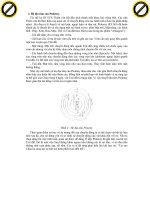
Figure 1 shows a recursive procedure of
forming double semi-circle for making
multiband antenna.
<b>Figure 1. Recursive procedure of forming double </b>
<b>semi-circle antenna </b>
</div>
<span class='text_page_counter'>(3)</span><div class='page_container' data-page=3>
the following equations [13]:
𝑎 = 𝐹
{1 +<sub>𝜋𝜀𝑟𝐹 [𝑙𝑛 (</sub>2ℎ 𝜋𝐹<sub>2ℎ) + 1.7726]}</sub>1/2 (1)
𝐹 =8.791𝑥109
𝑓<sub>𝑟</sub><sub>√𝜀</sub><sub>𝑟</sub> (2)
where <i>r</i> is the dielectric constant, <i>fr</i> is the
resonant frequency and <i>h</i> is the height of
the substrate<b>. </b>
After that, the combination of two above
single antennas is formed and it makes the
third band by the difference between two
semi-circles. Finally, the feed line is
optimize to match with the antenna
through a quarter wave transformer and a
characteristic impedance of 50 is
obtained approximately by the following
equations [13]:
𝑍0
= 120𝜋
√𝜀𝑒𝑓𝑓𝑥 [𝑊<sub>ℎ + 1.393 +</sub>2<sub>3 𝑙𝑛 (</sub>𝑊<sub>ℎ + 1.444)]</sub>
(4)
𝜀<sub>𝑒𝑓𝑓</sub> =𝜀𝑟+ 1
2 +
𝜀<sub>𝑟</sub>− 1
2 [1 + 12
ℎ
𝑊]
1
2
(5)
where <i>eff</i> is the effective dielectric
constant and W is the width of the feeding
line. The single antenna gets a total size
of 11110.79 mm3.
The geometric structure of the proposed
tri-band MIMO antenna is shown in
Figure 2. The MIMO model is
constructed by placing two antenna
elements side by side in horizontal as well
as vertical at the distance of about 0.5 at
28 GHz resonant frequency from circle
center to circle center. From edge to edge,
the distances between patches are so tiny.
The smallest distance is about 0.96 mm
which is equal 0.0896 at 28GHz.
(a) Top plane (b) Bottom plane
<b>Figure 2. The proposed multiband MIMO </b>
<b>antenna </b>
To reduce the mutual coupling between
MIMO elements for all three bands of
antenna, a novel EBG structure which is
developed from non-periodic and round
EBG structure [14] is proposed and
placed among patches. This structure has
a cross shape which is made of four parts.
Each part is a non-periodic and round
EBG and makes a multi-band decoupling
structure as shown in Figure 3.
(a) A structure of non-periodic and round EBG
(b) Equivalent circuit
</div>
<span class='text_page_counter'>(4)</span><div class='page_container' data-page=4>
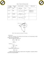
<b>Table 1. Dimension of the EBG structure </b>
<i><b>Parameter </b></i> <i><b>Value </b></i>
<i><b>(mm) </b></i>
<i><b>Parameter </b></i> <i><b>Value </b></i>
<i><b>(mm) </b></i>
r1 0.3 d1 6.5
r2 0.265 d2 4.25
h 0.79
<b>3. SIMULATION RESULTS </b>
The performance of the proposed MIMO
antenna as well as EBG structure have
simulated in CST software.
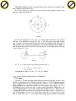
<b>3.1. Band-gap characteristic of EBG </b>
<b>structure </b>
The S12 parameter of EBG structure is
shown in Figure 4. It is obvious that there
are two an average of 20dB reduction in
the transmission coefficient. Optimizing
by CST simulation, we get two stop bands
of 17GHz-29.5 GHz and over 33 GHz
frequency band. Thus, it is suitable for
decreasing mutual coupling for multiband
MIMO antenna which operates at 28
GHz, 38 and 43GHz bands of 5G
application.
<b>Figure 4. Simulated transmission coefficient </b>
<b>of the proposed round patch EBG structure </b>
<b>with different d1 and d2 </b>
<b>3.2. 4x4 multiband MIMO antenna with </b>
<b>EBG </b>
The simulation results of the reflection
coefficients of 44 double semi-circle
MIMO antennas using round patch EBG
structure are shown in Figure 5. It is
clearly seen that here are three
frequencies at which resonance occurs.
They are 28 GHz, 38 GHz and 43 GHz
with large bandwidth of 2 GHz, 3.7 GHz
and 10.68 GHz, respectively. These
bandwidths cover four bands of 5G which
are 27.5-29.5 GHz; 37-40.5 GHz;
42.5-43.5 GHz; 45.5-50.2 GHz.
Thanks to cross EBG structures, the
mutual coupling between antenna
elements is quite low with the S12 get
under -15 dB at nearly all over operating
bands. It is the same for Enveloped
Correlation Coefficient (ECC) which is
one of important factors in MIMO
antenna. ECC of the proposed 44 MIMO
antenna can be obtained using formula
show in Equation (6) where i=1 to 4, j=1
to 4, and N=4 [15].
|𝜌𝑒(𝑖, 𝑗, 𝑁)|
= |∑ 𝑆𝑖,𝑁
∗
𝑁
𝑛=1 SN,j|
√|∏ [1 − ∑ 𝑆<sub>𝑖,𝑁</sub>∗ <sub>𝑆</sub>
𝑁,𝑘
𝑁
𝑛=1 ]
𝑘(=𝑖,𝑗) |
(6)
Using CST software, the correlation
factor curve of the proposed MIMO
antenna at three bands is shown in Figure
6. From this figure, the tri-band MIMO
antenna using round EBG structure has
the simulated ECC lower than 0.02 for all
interest bands. Therefore, it is quite
suitable for mobile communication with
a minimum acceptable correlation
</div>
<span class='text_page_counter'>(5)</span><div class='page_container' data-page=5>
<b>Figure 5. The S parameters of MIMO antenna </b>
<b>Figure 6. ECC curve for MIMO antenna </b>
The 2D radiation patterns of the proposed
MIMO antenna are shown in Figure 7
with high directivity. The antenna gain
gets 6.05 dB, 7.49 dB and 7.43 dB at 28
GHz, 38GGHz and 43 GHz respectively.
<b>Figure 7. The 2D radiation pattern </b>
<b>of the proposed antenna </b>
The radiation efficiencies are rather good.
The antenna radiation gets 78%, 88% and
86% at 28 GHz, 38 GGHz and 43 GHz
respectively as shown in Figure 8.
<b>Figure 8. The efficiency of the proposed antenna </b>
<b>4. CONCLUSION </b>
In this paper, a compact multiband MIMO
antenna using double semi-circle structure
as well as the cross structure of round
patch EBG is proposed. The total MIMO
antenna occupies a small area of
16.36 18.26 0.79mm3 on the RT5880
substrate and can operate at 28 GHz, 38
GHz and 43 GHz. The MIMO antenna
gets the large bandwidths which are
2 GHz, 3.7 GHz and 10.68 GHz,
</div>
<span class='text_page_counter'>(6)</span><div class='page_container' data-page=6>
<b>REFERENCES </b>
[1] A. Gupta, R.K. Jha:, “Survey of 5G Network: Architecture and Emerging Technologies,” IEEE
Access, vol.3, pp. 1206-1232, 2015.
[2] ITU, “WRC 2019 item 1.13, preparation”, 2018.
[3] Wonbin Hong, Kwang-hyun Baek, Seungtae Ko, “Millimeter-wave 5G Antennas for Smartphones:
Overview and Experimental Demonstration,” IEEE Transaction on Antennas and Propagation, vol.
65, no. 12, pp. 6250-6261, Dec 2017.
[4] A. Verma, A. Punetha and D. Pant, “A Novel Quad Band Compact Meandered PIFA Antenna for
GPS, UMTS, Wimax, HiperLAN/2 Applications,” 2015 Second International Conference on
Advances in Computing and Communication Engineering, pp. 404-408, May 2015.
[5] Y. Belhadef and N. B. Hacene, “Multiband F-PIFA Fractal Antennas for the Mobile Communication
Systems,” International Journal of Computer Science Issues (IJCSI), vol.9, issue 2, no.1, pp.:
266-270, 2012.
[6] N. Kumar and G. Saini, “A Multiband PIFA with Slotted Ground Plane for Personal Communication
Handheld Devices,” International Journal of Engineering Research and Development, vol.7, no.11,
pp.70-74, 2013.
[7] M.S. Ahmad, C.Y. Kim, and J.G. Park, “Multishorting Pins PIFA Design for Multiband
Communications,” Int. J. Antennas Propag., vol.2014, pp. 1-10, 2014.
[8] Mu’ath J. Al-Hasan, Tayeb A. Denidni and Abdel-Razik Sebak, “Millimeter-wave compact EBG
structure for Mutual- Coupling Reduction Applications,” IEEE Transactions on Antennas and
Propagation, vol. 63, no. 2, pp. 823 - 828,Feb. 2015.
[9] Abdolmehdi Dadgarpour, Milad Sharifi Sorkherizi, Ahmed A. Kishk, "Wideband, Low loss Magneto
Electronic Dipole Antenna for 5G Wireless Network with Gain Enhancement Using Meta Lens and
Gap Waveguide Technology Feeding,”IEEE Transactions on Antennas and Propagation, vol.64,
no. 12, pp. 5094- 5101, 2016.
[10] Mohammad S. Sharawi, Symon K. Podilchak, Mohamed T. Hussain and Yahia M.M. Antar,
“Dielectric Resonator Based MIMO Antenna System Enabling Millimeter-Wave Mobile Devices,”
IET Microwaves, Antennas & Propagation, vol. 11, no. 2, pp. 287 - 293, Jan. 2017.
[11] Naser Ojaroudi Parchin, Ming Shen, and Gert Frølund Pedersen, “End-Fire Phased Array 5G
Antenna Design Using Leaf-Shaped Bow-Tie Elements for 28/38 GHz MIMO Applications,”
Ubiquitous Wireless Broadband (ICUWB), 2016 IEEE International Conference, Oct 2016.
[12] Menna El Shorbagy, Raed M. Shubair, Mohamed I. AIHajri, Nazih Khaddaj Mallat, “On the Design
of Millimetre-Wave Antennas for 5G,” Microwave Symposium (MMS), 2016 16th Mediterranean,
Nov 2016.
[13] Balanis C.A, “Antenna Theory: Analysis and Design,” Edition 3rd, Wiley, 2005.
</div>
<span class='text_page_counter'>(7)</span><div class='page_container' data-page=7>
Patch EBG Cell for 5G Applications”, International Conference on Advanced Technologies for
Communications (ATC2017), pp.64-69, 18-20 October 2017, Quy Nhon, Vietnam.
[15] Leeladhar et al., “A 2x2 Dual-Band MIMO Antenna with Polarization Diversity for Wireless
Applications,” Progress In Electromagnetics Research C, vol.61, pp.91-103, 2016.
[16] M.P. Karaboikis, V.C. Papamichael, G.F. Tsachtsiris, and V.T. Makios, "Integrating compact
printed antennas onto small diversity/MIMO terminals," IEEE Transactions on Antennas and
Propagation, vol. 56, pp. 2067-2078, 2008.
<b>Biography: </b>
Duong Thi Thanh Tu received B.E, M.E degrees in Electronics and
Telecommunications from Hanoi University of Science and Technology and National
University in 1999 and 2005, respectively. She received PhD degree from
the School of Electronics and Telecommunications, Hanoi University of Science and
Technology in April 2019. She now is a senior lecturer at Faculty of
Telecommunications 1, Posts and Telecommunications Institute of Technology. Her
research interests include antenna design for next generation wireless networks as
well as the special structure of material such as metamaterial, electromagnetic
band gap structure.
</div>
<span class='text_page_counter'>(8)</span><div class='page_container' data-page=8>
<b>Số 20 27 </b>
<i><b> </b></i>
</div>
<!--links-->
tim xe oto da qua su dung can than keo gap co
- 3
- 307
- 0


, 2016 16th Mediterranean, </a> <br /> </p><!-- <p class="text-xl pb-40 overlay-read-more absolute bottom-0 left-0 w-full text-center bg-gradient-to-t from-white to-transparent">--><!----><!-- </p>--><!-- </div>--><!-- <a href="javascript:" class="bg-secondary px-6 py-2 rounded text-white absolute bottom-0 left-1/2 mb-4 transform -translate-x-1/2" id="showmore">Xem Thêm</a>--> </div> <div style="position: relative;" class="col-span-3 hidden md:block px-1 text-center"> <div style="position: sticky;top: 10px;width: 300px; height: 600px;"> <ins class="adsbygoogle" style="display:inline-block;width:300px;height:600px" data-ad-client="ca-pub-2979760623205174" data-ad-slot="8377321249"></ins><script defer>(adsbygoogle = window.adsbygoogle || []).push({});</script> </div> </div> </div> <div class="vf_link_relate px-2 my-2"> <h2 class="vf_doc_relate text-2xl font-bold my-4">Tài liệu liên quan</h2> <ul class="grid grid-cols-12 gap-2"> <li class="col-span-6 md:col-span-2"> <div class="card-doc " onclick="actionDocRelated(this)"> <a class="card-doc-img" href="https://text.123docz.net/document/1629918-tim-xe-oto-da-qua-su-dung-can-than-keo-gap-co.htm" title="tim xe oto da qua su dung can than keo gap co"> <i class="icon i_type_doc i_type_doc1"></i> <img class="lazy" src="data:image/gif;base64,R0lGODlhAQABAIAAAP///wAAACH5BAEAAAAALAAAAAABAAEAAAICRAEAOw==" data-src="https://media.store123doc.com/images/document/2014_07/03/medium_pru1382453198.jpg" width="124" height="179" alt="tim xe oto da qua su dung can than keo gap co" onerror="this.src=)