Use carbon nanotubes and graphene oxide absorbed copper ion
Bạn đang xem bản rút gọn của tài liệu. Xem và tải ngay bản đầy đủ của tài liệu tại đây (615.32 KB, 54 trang )
THAI NGUYEN UNIVERSITY
UNIVERSITYOF AGRICULTURAL AND FORESTRY
GIANG NAM KHÁNH
TOPIC TITLE:USE CARBON NANOTUBES AND GRAPHENE
OXIDE ABSORBED COPPER ION
BACHELOR THESIS
Study Mode
: Full-time
Major
: Environmental Science And Management
Faculty
: International Training and Development Center
Batch
: 2010 - 2015
Thai Nguyen, 21/01/2015
ACKNOWLEDGMENT
First of all, I would like to express sincere thanks to the school board Thai
Nguyen University of Agriculture and Forestry, Faculty of International Training and
Development; advanced program, thank the teachers who has imparted to me the
knowledge and valuable experience during the process of learning and researching
here.
In the process of implementing and completing thesis, I have received the
enthusiastic help of the teachers of National Tsing Hua University. I would like to
express my special thanks to Prof. Ruey An Doong who has spent a lot of time, created
favorable conditions, enthusiastic to guide me to complete this thesis.
I sincerely thank my friends in the laboratory facilitated, and provided the
information and data necessary for my implementation process and helped me finish
this thesis.
In the process of implementing the project, due to time, financial and research
levels of myself is limited so this project is inevitable shortcomings. So, I would like
to receive the attention and feedback from teachers and friends to this thesis is more
complete.
I sincerely thank you!
Taiwan, 2014
Students perform
Giang Nam Khanh
Table of Contents
Abstract .......................................................................................................................................... 1
1. INTRODUCTION .................................................................................................................... 3
1.1 Rationale of study ....................................................................................................... 3
1.2 Aim of the study ......................................................................................................... 5
1.3 Research questions ..................................................................................................... 5
1.4 Scope of the study....................................................................................................... 5
2. LITERATURE REVIEW ......................................................................................................... 5
2.1 Carbon nanotube (CNTs) ............................................................................................ 6
2.1.1 Structure of Carbon nanotubes ............................................................................. 6
Single-walled ................................................................................................................. 7
Multi-walled .................................................................................................................. 9
2.1.2 Properties adsorption of Carbon Nanotubes (CNTs) .......................................... 10
2.1.3 Applications of Carbon Nanotubes..................................................................... 13
2.2 Graphene oxide (GO) ............................................................................................... 15
2.2.1 Structure of Graphene oxide (GO) ..................................................................... 15
2.2.2 Properties adsorption of Graphene oxide (GO) .................................................. 19
2.2.3 Applications of Graphene oxide ......................................................................... 21
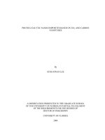
2.3 Atomic Absorption Spectrometric machine (AAS) .................................................. 23
3. MATERIALS AND METHODOLOGY ............................................................................. 26
3.1 MATERIALS ............................................................................................................. 26
3.1.1 Carbon nanotubes (CNTs) .................................................................................... 26
3.1.2 Graphene oxide (GO) ......................................................................................... 27
3.1.3 Solution Cu2+ ...................................................................................................... 29
3.2 METHODOLOGY ................................................................................................... 30
3.2.1 Carbon nanotubes (CNTs) .................................................................................. 30
3.2.2 Graphene oxide (GO) ......................................................................................... 30
4. RESULTS AND DISCUSSION ........................................................................................... 32
4.1 RESULTS ................................................................................................................. 32
4.1.1 Results of solution Cu2+........................................................................................ 32
4.1.2 Carbon nanotubes (CNTs) .................................................................................. 33
4.1.3 Graphene oxide (GO) ......................................................................................... 36
4.2 Discussion ................................................................................................................ 39
4.2.1 Carbon nanotubes (CNTs) ...................................................................................... 39
4.2.2 Graphene oxide (GO) ......................................................................................... 40
5. CONCLUSION ........................................................................................................................ 42
REFERENCES ............................................................................................................................ 43
LIST OF ABBREVIATIONS
AAS
Atomic Absorption Spectrometric
AFM
Atomic force microscopy
CNTs
Carbon nanotubes
DSC
Differential scanning calorimetry
DWNTs
Double-walled carbon nanotubes
F-AAS
Flame atomic absorption spectrometry
FT-IR
Infrared spectroscopy
GO
Graphene oxide
MWNTs
Multi-walled carbon nanotubes
PZC
Point of zero charge
SWNTs
Single-walled carbon nanotubes
XRD
X-ray diffraction
XPS
X-ray photoelectron spectroscopy
RSD
Relative standard deviation
LIST OF TABLES
Table 3.1. Stock solution………………..………………………………………………..30
Table 4.1. The volume of the stock solution based on the concentration of the final
volume……………………………………………………………………………………32
Table 4.2. Concentration before add CNTs and GO………………………….……….…33
Table 4.3 The concentration after use Atomic Absorption Spectrometric of CNTs…..…34
Table 4.4 The adsorption capacity q (mg/g CNTs) of CNTs..………………….………..35
Table 4.5 The concentration after use Atomic Absorption Spectrometric of GO...…...…36
Table 4.6 The adsorption capacity q (mg/g CNTs) of GO…..………………….….…….38
LIST OF FIGURES
Figure 2.1. The (n,m) nanotube naming scheme can be thought of as a vector (Ch) in an
infinite graphene sheet that describes how to "roll up" the graphene sheet to make the
nanotube. T denotes the tube axis, and a1 and a2 are the unit vectors of graphene in real
space...………………………………………………………………………..……………8
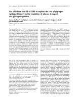
Figure 2.2. Structure of the GO…………………………………………….…………….19
Figure 2.3. Diagram systems AAS Atomic Absorption………………………………….24
Figure 3.1. Heat to appropriate temperature (35oc) for 10 hour………………………….27
Figure 3.2. Rotary – Vacuum – Evaporate……………………………….………………28
Figure 4.1. Concentration adsorption of CNTs……………………...…………….……..34
Figure 4.2 Adsorption capacity of CNTs.………………………………..………..……...36
Figure 4.3 Concentration adsorption of GO……………………………………..….……37
Figure 4.4 Adsorption capacity of GO…………………………………………..……….38
ABSTRACT
Thai Nguyen University of Agriculture and Forestry
Degree Program
Bachelor of Environmental Science and Management
Student name
Giang Nam Khanh
Student ID
DTN 1053180062
Thesis Title
Adsorption of copper ions by carbon nanotubes and
graphene oxides
Supervisor (s)
Prof. Ruey An Doong
Assoc.Prof. Dam Xuan Van
Abstract:
Copper is an element with atomic number of 29 and is heavy metal ion in the water which is
not only harmful to the environment but also human health. The study using carbon nanotubes
and graphene oxide nanomaterial to absorb copper oxide ion in water is absolutely necessary.
Prepare a quantity carbon nanotubes and graphene oxide required like in the calculation and
clean them with as required of the experiment (pH, drying, and ensure it is unique).
Prepare a solution containing Cu 2+ by means of synthetic compounds Cu(NO3)2 + 2 H2O in
5 tubes test at concentrations of was calculated from the previous.
To absorb Cu2+, we used direct absorption from the nanomaterials already used for solution
into 5 tubes test containing Cu2+ ion solution with different concentrations. Then, apply the
appropriate conditions for the best absorption. After the appropriate time 2 hour, 4 hour, 6
1
hour, we will absorb the sample to measure the concentration of Cu 2+ in solution by Atomic
Absorption Spectrometric machine. The last result of the absorption of the formula we use to
calculate the adsorption capacity of the carbon nanotubes and graphene oxide. Concluded:
volume, solution concentration, time, conditions similar in laboratory, we identified graphene
oxide Cu2+ ion absorption better than carbon nanotubes.
Keywords: Absorb, Atomic Absorption Spectrometric, Carbon nanotubes, Graphene oxide,
Copper(II)
Number of pages:
47
Date of Submision :
2
1. INTRODUCTION
1.1 Rationale of study
The 21st century is the reign of nanotechnology. Nanotechnology has brought to the
world many astonishing applications for life. Scientists, industrialists and manufacturers
always pay attention to every detail of the development of this technology, also the
nature, characteristics and applications of it. The new properties of nanotechnology are
results of the reducing in the size of materials to nanometers; this changes the mechanism
of quantum interference. People often call this phenomenon is the size effect or the
confinement effect. As a result, nano-materials are used a lot in practice, becoming super
hard, super durable, and superconductivity products.
Heavy metals in water have been a major preoccupation for many years because of their
toxicity towards aquatic-life, human beings and the environment. As they do not degrade
biologically like organic pollutants, their presence in drinking water or industrial effluents
is a public health problem due to their absorption and therefore possible accumulation in
organ-isms. Several processes have been used and developed over the years to remove
metal ions, such as chemical precipitation, reverse osmosis, electrolytic recovery, ion
exchange or adsorption. The latter has been studied for both mineral and organic materials
(Bailey et al, 1999; Ricordel et al, 2001). Moreover, one of the important properties of
solid matrices explored is related to the adsorption of trace elements taking
preconcentration or separation into account, where from a complex mixture, a single
3
element or a group of elements can be separated and quantitatively determined (Pyrzynska
et al, 1999; Camel et al, 2003). Carbon nanotubes (CNTs), a member in carbon family,
are relatively new adsorbents that have been proven to possess great potential for
removing many kinds of pollutants such as chlorobenzenes (Peng et al, 2003), herbicides
as well as lead and cadmium ions (Li et al,2003 ). The hexagonal arrays of carbon atoms
in graphite sheets of CNTs surface have strong interactions with other molecules or
atoms. The study of adsorption properties of carbon nanotubes is important in both
fundamental and practical point of view. The studies on the adsorption of heavy metals
with CNTs presented in the literature are limited to a few examples, thus, in this work, the
analytical potential of CNTs as an adsorbent was examined for wider range of metal ions.
The effect of solution conditions such as pH value and metal ion concentration on the
adsorption behavior was investigated. Moreover, the kind of preliminary treatment
processing of CNTs resulting the nanotube surface status was checked as it could
significantly influence their adsorption efficiency.
Graphene oxide (GO) is a super adsorbent with a great potential for removing cationic
heavy-metal contaminants from water. The adsorption capacities of graphene oxide for
lead (Pb2+), cobalt (Co2+), copper (Cu2+), and cadmium (Cd2+) are over an order of
magnitude greater than the adsorption capacities of conventional adsorbents such as
activated carbon and iron-oxide nanoparticles. Even for uranium (UO22+), which is bulky
and subject to complexation with hydroxide and carbonate anions in aqueous solution,
graphene oxide has exhibited an adsorption capacity surpassing any known natural and
4
engineering materials (Willner,2012). Graphene oxide is a two-dimensional nanomaterial
(i.e., material with size in one dimension being negligible compared to the sizes in the
other two dimensions) that can be readily produced by exfoliating naturally occurring
graphite under oxidation (Li et al, 2008).
1.2 Aim of the study
The pollution of the environment in general and water pollution in particular becomes
more and more serious in Vietnam. Accessing to the mass media every day, we can easily
come across the image and information of water pollution. Hence, the development of
technology in water treatment is increasingly urgent. Also, research of using the
compounds of carbon (nano carbontubes and graphene oxide) to remove metal ions and
water pollutants is absolutely necessary. The study mentions using carbon nanotubes and
graphene oxide to absorb ion copper (Cu2+) that contaminates water sources,
simultaneously comparing efficiency of those compounds to find out which one has better
ion copper absorbance.
1.3 Research questions
What are the efficiency of carbon nanotubes and graphene oxide in absorption of ion
copper? And which one is better in comparison?
1.4 Scope of the study
Due to experiment using nanomaterial with high cost and need to used computer for
checking, so the experiment was take place in the laboratory.
5
2. LITERATURE REVIEW
2.1 Carbon nanotube (CNTs)
2.1.1 Structure of Carbon nanotubes
The carbon nanotubes (English: Carbon nanotubes - CNTs) are allotropes of carbon
forms. A single-layer carbon nanotube is a graphite sheet thickness-a-cause death rolled
into a cylindrical instant, with a nanometer in diameter. This happened in the nanostructure in which the ratio between length and diameter in excess of 10,000. These
cylindrical carbon molecules have interesting properties that make them potentially useful
in many applications of nanotechnology, industrial electronics, optics, and some other
school. They show incredible strength and unique electrical properties, and thermal
conductivity effect. Inorganic nanotubes have also been synthesized.
Nanotubes are a fullerene structure, which also includes buckyballs. While the spherical
buckyballs, nanotubes have a cylindrical shape, with at least one head is covered by a
hemispherical buckyball structure. Their names were placed in their shape, the diameter
of the nanotube due to the size of a few nanometers (approximately 50,000 times smaller
than a human hair), while their length can be up to several millimeters. Researchers at the
University of Cincinnati (UC) have developed a process to build networks of carbon
nanotubes aligned extremely long. They were able to produce carbon nanotubes 18mm
long and can fold into carbon nanofibers. There are two main types of nanotubes: singlelayer nanotubes (SWNT) and multi-layer nanotubes (MWNT). The nature of the link in
the carbon nanotube is explained by quantum chemistry, namely the orbital overlap.
6
Chemical bonding of nanotubes is composed entirely by linking sp2, similar to graphite.
This link structure, stronger links in the sp3 diamond creates molecules with exceptional
durability. The nanotubes are typically self-organized into "ropes" held together by Van
der Waals forces. Under high pressure, nanotubes can merge together, exchange some
links sp2 to sp3 link, creating the ability to produce strong rope, the length is not limited
by the pressure nanotube linking high.
Single-walled
Most single-walled nanotubes (SWNTs) have a diameter of close to 1 nanometer, with a
tube length that can be many millions of times longer. The structure of a SWNT can be
conceptualized by wrapping a one-atom-thick layer of graphite called graphene into a
seamless cylinder. The way the graphene sheet is wrapped is represented by a pair of
indices (n, m). The integer’s n and m denote the number of unit vectors along two
directions in the honeycomb crystal lattice of graphene. If m = 0, the nanotubes are called
zigzag nanotubes, and if n = m, the nanotubes are called armchair nanotubes. Otherwise,
they are called chiral. The diameter of an ideal nanotube can be calculated from its (n,m)
indices as follows
d=
= 78.3
where a=0.246nm
SWNTs are an important variety of carbon nanotube because most of their properties
change significantly with the (n,m) values, and this dependence is non-monotonic (see
7
Kataura plot). In particular, their band gap can vary from zero to about 2 eV and their
electrical conductivity can show metallic or semiconducting behavior. Single-walled
nanotubes are likely candidates for miniaturizing electronics. The most basic building
block of these systems is the electric wire, and SWNTs with diameters of an order of a
nanometer can be excellent conductors. One useful application of SWNTs is in the
development of the first intermolecular field-effect transistors (FET). The first
intermolecular logic gate using SWCNT FETs was made in 2001(Dalton, 2013). A logic
gate requires both a p-FET and an n-FET. Because SWNTs are p-FETs when exposed to
oxygen and n-FETs otherwise, it is possible to protect half of an SWNT from oxygen
exposure, while exposing the other half to oxygen. This results in a single SWNT that acts
as a not logic gate with both p and n-type FETs within the same molecule.
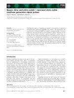
Figure 2.1. The (n,m) nanotube naming scheme can be thought of as a vector (Ch) in an
infinite graphene sheet that describes how to "roll up" the graphene sheet to make the
nanotube. T denotes the tube axis, and a1 and a2 are the unit vectors of graphene in real
space.
8
Multi-walled
Multi-walled nanotubes (MWNTs) consist of multiple rolled layers (concentric tubes) of
graphene. There are two models that can be used to describe the structures of multiwalled nanotubes. In the Russian Doll model, sheets of graphite are arranged in
concentric cylinders, a (0,8) single-walled nanotube (SWNT) within a larger (0,17)
single-walled nanotube. In the Parchment model, a single sheet of graphite is rolled in
around itself, resembling a scroll of parchment or a rolled newspaper. The interlayer
distance in multi-walled nanotubes is close to the distance between graphene layers in
graphite, approximately 3.4 Å. The Russian Doll structure is observed more commonly.
Its individual shells can be described as SWNTs, which can be metallic or
semiconducting. Because of statistical probability and restrictions on the relative
diameters of the individual tubes, one of the shells, and thus the whole MWNT, is usually
a zero-gap metal. Double-walled carbon nanotubes (DWNTs) form a special class of
nanotubes because their morphology and properties are similar to those of SWNTs but
their resistance to chemicals is significantly improved. This is especially important when
functionalization is required (this means grafting of chemical functions at the surface of
the nanotubes) to add new properties to the CNT. In the case of SWNTs, covalent
functionalization will break some C=C double bonds, leaving "holes" in the structure on
the nanotube and, thus, modifying both its mechanical and electrical properties. In the
case of DWNTs, only the outer wall is modified. DWNT synthesis on the gram-scale was
first proposed in 2003 by the CCVD technique, from the selective reduction of oxide
solutions in methane and hydrogen.
9
The telescopic motion ability of inner shells and their unique mechanical properties will
permit the use of multi-walled nanotubes as main movable arms in coming
nanomechanical devices. Retraction force that occurs to telescopic motion caused by the
Lennard-Jones interaction between shells and its value is about 1.5 nN (Zavalniuk, 2011).
2.1.2 Properties adsorption of Carbon Nanotubes (CNTs)
The properties of MWNTs are generally similar to those of regular polyaromatic solids
(which may exhibit graphitic, turbostratic or intermediate crystallographic structure).
Variations are mainly due to different textural types of the MWNTs considered
(concentric, herringbone, bamboo) and the quality of the nanotexture, both of which
control the extent of anisotropy. Actually, for polyaromatic solids that consist of stacked
graphenes, the bond strength varies significantly depending on whether the in-plane
direction is considered (characterized by very strong covalent and therefore very short
0.142 nm bonds) or the direction perpendicular to it (characterized by very weak van der
Waals and therefore very loose ≈ 0.34 nm bonds). Such heterogeneity is not found in
single (isolated) SWNTs. However, the heterogeneity returns, along with the related
consequences, when SWNT sassociate into bundles. Therefore, the properties, and
applicability of SWNT s may also change dramatically depending on whether single
SWNT or SWNT ropes are involved. An important problem to solve when considering
adsorption onto nanotubes is to identify the adsorption sites. The adsorption of gases into
a SWNT bundle can occur inside the tubes (internal sites), in the interstitial triangular
channels between the tubes, on the outer surface of the bundle (external sites), or in the
10
grooves formed at the contacts between adjacent tubes on the outside of the bundle.
Experimental adsorption studies on CNTs have confirmed the adsorption on internal,
external and groove sites. Modeling studies have pointed out that the convex surface of
the CNTs is more reactive than the concave one and that this difference in reactivity
increases as the tube diameter decreases. Compared to the highly bent region in
fullerenes, CNTs are only moderately curved and are expected to be much less reactive
towards dissociative chemisorption. Models have also predicted enhanced reactivity at the
kink sites of bent CNTs. Additionally, it is worth noting that unavoidable imperfections,
such as vacancies, Stone–Wales defects, pentagons, heptagons and dopants, are believed
to play a role in tailoring the adsorption properties (Lu et al, 2005). Considering closedend SWNTs first, simple molecules can be adsorbed onto the walls of the outer nanotubes
of the bundle and preferably on the external grooves. In the first stages of adsorption
(corresponding to the most attractive sites for adsorption), it seems that adsorption or
condensation in the interstitial channels of the SWNT bundles depends on the size of the
molecule (and/or on the SWNT diameters) and on their interaction energies. Opening the
tubes favors gas adsorption (including O2 ,N2 within the inner walls (Fujiwara et al,
2001;Yang et al, 2002). It was found that the adsorption of nitrogen on open-ended
SWNT bundles is three times larger than that on closed-ended SWNT bundles. The
significant influence that the external surface area of the nanotube bundle has on the
character of the surface adsorption isotherm of nitrogen (type I, II or even IV of the
IUPAC classification) has been demonstrated from theoretical calculations (Jiang et al;
2003). Additionally, it has been shown that the analysis of theoretical adsorption
11
isotherms, determined from a simple model based on the formalism of Langmuir and
Fowler, can help to experimentally determined the ratio of open to closed SWNTs in a
sample. For hydrogen and other small molecules like CO, computational methods have
shown that, for open SWNTs, the pore, interstitial and groove sites are energetically more
favorable than surface sites (Zhao et al, 2002). In the case of carbon monoxide, aside
from physisorbed CO, CO hydrogen bonds to hydroxyl functionalities created on the
SWNTs by acid purification have been identified (Matranga et al, 2005). FTIR and
temperature-programmed desorption (TPD) experiments have shown that NH3 or NO2
adsorb molecularly and that NO2 is slightly more strongly bound than NH3. For NO2, the
formation of nitrito (O-bonded) complexes is preferred to nitro (N-bonded) ones. For
ozone, a strong oxidizing agent, theoretical calculations have shown that physisorption
occurs on ideal, defect-free SWNT, whereas strong chemisorption occurs on Stone–
Wales defects, highlighting the key role of defective sites in adsorption properties
(Picozzi et al, 2004). For MWNTs, adsorption can occur in the aggregated pores, inside
the tube or on the external walls. In the latter case, the presence of defects, as incomplete
graphene layers, must be taken into consideration. Although adsorption between the
graphenes (intercalation) has been proposed in the case of hydrogen adsorption in hMWNTs or platelet nanofibers (Chambers et al, 1998), it is unlikely to occur for many
molecules due to steric effects and should not prevail for small molecules due to the long
diffusion paths involved. In the case of inorganic fluorides (BF3, TiF4, NbF5 and WF6 ),
accommodation of the fluorinated species into the carbon lattice has been shown to result
from intercalation and adsorption/condensation phenomena (Giraudet et al, 2003). Only a
12
few studies deal with adsorption sites in MWNTs, but it has been shown that butane
adsorbs more onto MWNTs with smaller outside diameters, which is consistent with
another statement that the strain on curved graphene surfaces affects sorption. Most of the
butane adsorbs to the external surface of the MWNTs while only a small fraction of the
gas condenses in the pores (Hilding et al, 2001). Comparative adsorption of krypton or of
ethylene onto MWNTs or onto graphite has allowed scientists to determine the
dependence of the adsorption and wetting properties of the nanotubes on their specific
morphologies. Nanotubes were found to have higher condensation pressures and lower
heats of adsorption than graphite (Masenelli-Varlot et al, 2002). These differences are
mainly due to decreased lateral interactions between the adsorbed molecules, related to
the curvature of the graphene sheets.
2.1.3 Applications of Carbon Nanotubes
Near - Field Microscope Probes
The high mechanical strength of carbon nanotubes makes them almost ideal candidates
for use as force sensors in scanning probe microscopy (SPM). They provide higher
durability and the ability to image surfaceswith a high lateral resolution, the latter being a
typicallimitation of conventional force sensors (based on ceramic tips). The idea was first
proposed and tested by Dai et al (Dai et al, 1996) using c-MWNTs. It was extended to
SWNTs by Hafner et al (Cassel et al, 1999), since small-diameter SWNTs were believed
to give higher resolution than MWNTs due to the extremely short radius of curvature of
the tube end. However, commercial nanotube-based tips (such as those made by
13
Piezomax, Middleton, WI, USA) use MWNTs for processing convenience. It is also
likely that the flexural modulus of a SWNT is too low, resulting in artifacts that affect the
lateral resolution when scanning a rough surface. On the other hand, the flexural modulus
of a c-MWNT is believed to increase with the number of walls, although the radius of
curvature of the tip increases at the same time. Whether based on SWNT or MWNT ,such
SPM tips also offer the potential to be functionalized, leading to the prospect of selective
imaging based on chemical discrimination in chemical force microscopy (CFM).
Chemical function imaging using functionalized nanotubes represents a huge step forward
in CFM because the tip can be functionalized very specifically (ideally only at the very tip
of the nanotube, where the reactivity is the highest), increasing the spatial resolution. The
interaction between the chemical species present at the end of the nanotube tip and the
surface containing chemical functions can be recorded with great sensitivity, allowing the
chemical mapping of molecules (Kitiyanan et al, 2000).
Field Emission-Based Devices
In a pioneering work by de Heer et al (Heer et al,1995), carbon nanotubes were shown to
be efficient field emitters and this property is currently being used several applications,
including flat panel displays for television sets and computers (the first prototype of such
a display was exhibited by Samsung in 1999), and devices requiring an electronproducing cathode, such as X-ray sources. Briefly, a potential difference is set up between
the emitting tips and an extraction grid so that electrons are pulled from the tips onto an
electron-sensitive screen layer. Replacing the glass support and protecting the screen
14
using a polymer-based material should even permit the development of flexible screens.
Unlike regular (metallic) electron-emitting tips, the structural perfection of carbon
nanotubes allows higher electron emission stability, higher mechanical resistance, and
longer lifetimes. Most importantly, using them saves energy since the tips operate at a
lower heating temperature and require much lower threshold voltage than in other setups.
2.2 Graphene oxide (GO)
2.2.1 Structure of Graphene oxide (GO)
Graphite oxide, formerly called graphitic oxide or graphitic acid, is a compound
of carbon, oxygen and hydrogen in variable ratios, obtained by treating graphite with
strong oxidizers. The maximally oxidized bulk product is a yellow solid with C:O ratio
between 2.1 and 2.9, that retains the layer structure of graphite but with a much larger and
irregular spacing. Graphene, is a thin layer of pure carbon; it is a single, tightly packed
layer of carbon atoms that are bonded together in a hexagonal honeycomb lattice. In more
complex terms, it is an allotrope of carbon in the structure of a plane of sp2 bonded atoms
with a molecule bond length of 0.142 nanometres. Layers of graphene stacked on top of
each other form graphite, with an interplanar spacing of 0.335 nanometres.
While graphite is a 3 dimensional carbon based material made up of millions of layers of
graphene, graphite oxide is a little different. By the oxidation of graphite using strong
oxidizing agents, oxygenated functionalities are introduced in the graphite structure which
not only expand the layer separation, but also makes the material hydrophilic (meaning
15
that they can be dispersed in water). This property enables the graphite oxide to be
exfoliated in water using sonication, ultimately producing single or few layer graphene,
known as graphene oxide (GO). The main difference between graphite oxide and
graphene oxide is, thus, the number of layers. While graphite oxide is a multilayer system
in a graphene oxide dispersion a few layers flakes and monolayer flakes can be found.
The structure and properties of graphite oxide depend on particular synthesis method and
degree of oxidation. It typically preserves the layer structure of the parent graphite, but
the layers are buckled and the interlayer spacing is about two times larger (~0.7 nm) than
that of graphite. Strictly speaking "oxide" is an incorrect but historically established
name. Besides oxygen epoxide groups (bridging oxygen atoms), other functional groups
experimentally found are: carbonyl (C=O), hydroxyl (-OH), phenol, for graphite oxides
prepared using sulphuric acid (e.g. Hummers method) also some impurity of sulphur is
often found, for example in a form of organo sulfate groups. There is evidence of
"buckling" (deviation from planarity), folding and cracking of graphene oxide sheets upon
deposition of the layers on a choice of substrate. The detailed structure is still not
understood due to the strong disorder and irregular packing of the layers (Lei, 2013).
Graphene
oxide
layers
are
about
1.1
±
0.2 nm
thick. Scanning
tunneling
microscopy shows the presence of local regions where oxygen atoms are arranged in a
rectangular pattern with lattice constant 0.27 nm × 0.41 nm. The edges of each layer are
terminated with carboxyl and carbonyl groups. X-ray photoelectron spectroscopy shows
presence of
several C1s peaks, their number and relative intensity depending on
16
particular oxidation method used. Assignment of these peaks to certain carbon
functionalization types is somewhat uncertain and still under debates. For example, one of
interpretations goes as following: non-oxygenated ring contexts (284.8 eV), C-O (286.2
eV), C=O (287.8 eV) and O-C=O (289.0 eV). Another interpretation using density
functional theory calculation goes as following: C=C with defects such as functional
groups and pentagons (283.6 eV), C=C (non-oxygenated ring contexts) (284.3 eV), sp3CH in the basal plane and C=C with functional groups (285.0 eV), C=O and C=C with
functional groups, C-O (286.5 eV), and O-C=O (288.3 eV).
Graphite oxide is hydrophilic and easily hydrated exposed to water vapor or immersed in
liquid water, resulting in a distinct increase of the inter-planar distance (up to 1.2 nm in
saturated state). Additional water is also incorporated into interlayer space due to high
pressure induced effects. Maximal hydration state of graphite oxide in liquid water
corresponds to insertion of 2-3 water monolayers, cooling the graphite oxide/H2O samples
results in "pseudo-negative thermal expansion" and below freezing point of water media
results in de-insertion of one water monolayer and lattice contraction. Complete removal
of water from the structure seems difficult since heating at 60–80 °C results in partial
decomposition and degradation of the material.
Similar to water, graphite oxide also easily incorporates other polar solvents, e.g.
alcohols. However, intercalation of polar solvents occurs significantly different in Brodie
and Hummers graphite oxides. Brodie graphite oxide is intercalated at ambient conditions
with by one monolayer of alcohols and several other solvents (e.g. dimethylformamide
17
and acetone) when liquid solvent is available in excess. Separation of graphite oxide
layers is proportional to the size of alcohol molecule. Cooling of Brodie graphite oxide
immersed in excess of liquid methanol, ethanol, acetone and dimethylformamide results
in step-like insertion of additional solvent monolayer and lattice expansion. The phase
transition detected by X-ray diffraction and DSC is reversible; de-insertion of solvent
monolayer is observed when sample is heated back from low temperatures. Additional
methanol and ethanol monolayer is reversibly inserted into the structure of Brodie
graphite oxide also at high pressure conditions.
Hummers graphite oxide is intercalated with two methanol or ethanol monolayers already
at ambient temperature. The interlayer distance of Hummers graphite oxide in excess of
liquid alcohols increases gradually upon temperature decrease, reaching 19.4 and 20.6 Å
at 140 K for methanol and ethanol, respectively. The gradual expansion of the Hummers
graphite oxide lattice upon cooling corresponds to insertion of at least two additional
solvent monolayers.
Graphite oxide exfoliates and decomposes when rapidly heated at moderately high
temperatures (~280–300 °C) with formation of finely dispersed amorphous carbon,
somewhat similar to activated carbon (Talyzin et al, 2009; You, 2013).
18