Crushing and screening handbook
Bạn đang xem bản rút gọn của tài liệu. Xem và tải ngay bản đầy đủ của tài liệu tại đây (7.86 MB, 260 trang )
Crushing and Screening Handbook
METSO MINERALS
Metso Minerals in brief
To be successful in today’s quarry and sand and
gravel operations, you need a partner to supply competitiveness, not just equipment. This
translates into a comprehensive source of global knowledge, financial resources, innovative
technologies and systems, and skilled people
in worldwide locations. Only one organization
in the world has the resources to bring you all
these capabilities for efficient aggregates process management – Metso Minerals.
Around 8,000 Metso Minerals people operate
in sales and manufacturing facilities and service shops in over 100 countries, covering all
continents. They supply you with world-class
equipment, complemented by comprehensive
service solutions aimed at increasing your operational reliability. In short, we do everything
possible to help ensure your success.
Whether you need a single crusher, a multistage process or a complete plant, we assist you
with the right design for the most cost-effective
crushing process. We are the world’s leading
supplier of both unit machines and complete
aggregates processing systems.
Comprehensive process solutions
Your system may involve a whole series of processes, such as crushing and screening, conveying,
classifying, washing and pretreatment, stockpiling, storage, loading and unloading, automation,
environmental control and wear protection.
Using sophisticated project tools, our experienced engineers will arrange the appropriate
equipment into a balanced system to provide
you the high quality end-products you require,
at the lowest cost per ton. We also provide site
preparation, structural design, and supply and
erection plans.
Your trusted partner
Your partner of choice, Metso Minerals is the
trusted and preferred supplier in the rock
processing industry. Our highest priority
and personal commitment is to provide lifetime support and service for your aggregates
processing operations.
When designing a new plant, we balance raw
material characteristics with the required production rate and the size and shape of the finished product. After careful selection of each
piece of equipment from final screening to primary crushing your process characteristics are
optimum quality, productivity and reliability.
METSO MINERALS
700mm coarse
Hard Gabbro
450
507
t/h
B13-50-3V
Opening 100 mm
450
GP300S
coarse
2.4
306
Load 76 %
144
96 %
306
C110
quarry
2.6
TK13-20-3V
144
69 %
#20 mm/E93 %
306
55
10 m³
507
507
Setting 150 mm
89
225
Stroke 32 mm
Setting 43 mm
225
CVB1845 III
187
172
112
225
#50 mm/E93 %
#24 mm/E89 %
#6 mm/E85 %
GP300
fine
1.8
88 %
Stroke 40 mm
Setting 16 mm
225
395
36
CVB2050 III
373
#25 mm/E94 %
#13 mm/E80 %
#7 mm/E87 %
53
152
58
320
110
55
100 %
0/20mm
110
34 %
0/5mm
58
18 %
5/10mm
152
47 %
10/20mm
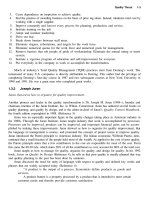
Process simulation technology
Complete stationary or mobile plants
The computerized “Bruno” process calculation
system has already become the proven standard in the crushing industry. Rock quality, feed
grading and selected machines are entered to
simulate the expected production capacities
and product gradings. Contact for more information.
Besides offering complete stationary installations, Metso Minerals is the pioneer in fully
mobile in-pit crushing operation. Integrating
two or three mobile crushing plants combined
with a mobile screen and a mobile conveying
system results in improved efficiency and endproduct accuracy.
METSO MINERALS
We have the expertise to build a fleet of track
mounted crushing and screening plants for primary, secondary and tertiary stages according
to your application. Moving along the quarry
face the track-mounted units replace dump
truck haulage, thus achieving substantial savings. The whole mobile plant can be moved
from site to site on standard trailers. This is one
example of how our worldwide process knowhow can serve your crushing, screening and
conveying needs.
Spare and wear parts – genuine parts always
close to you, no matter where you are located
worldwide.
Vertical shaft impactors – helps shape the
rock to high-quality aggregates. Rock on rock
crushing.
Broad product range
Stationary screens – an extensive range of
complete screening solutions for scalping,
closed circuit screening, final sizing and dewatering. Single inclination, double, triple and
horizontal models.
Feeders – a wide range of heavy duty feeders
designed to absorb impact, meter material to
the crusher and scalp out fines.
Sand and gravel washing – to produce special
quality rock materials for demanding construction projects, such as bridges.
Primary gyratory crushers – ideally suited to
all high-capacity primary hard rock crushing
applications.
Crusher automation – ensures consistent and
efficient operation. Improves productivity and
product quality while reducing maintenance
costs by preventing overload situations.
Jaw crushers – we have more installed jaw
crushers than anyone in the world. The leading choice due to their high reduction ratio and
heavy duty design.
Cone crushers – capacities available to suit all
secondary, tertiary or quarternary crushing applications. High performance technology.
Impact crushers – primary and secondary
machines for soft and medium-hard materials.
High reduction ratios. Can eliminate need for a
tertiary crushing stage.
Stationary conveyors – a complete range of
belt conveyors. Wide variety of widths, lengths,
accessories and options. Various models incorporate truss frames that are simple, compact
and fast to dismantle, transport and erect.
Track-mounted crushing plants – fully mobile jaw, cone or impact crushing plants, with
or without screens, and equipped with open or
closed circuit and discharge conveyors. Easily
transportable on standard trailers.
METSO MINERALS
Portable crushing plants – excellent transportability between sites and fast installation,
in addition to high crushing capacities. Can be
fitted with jaw, cone or impact crushers, with
or without screens, and equipped with open or
closed circuit and discharge conveyors.
Mobile screens – track-mounted units for excellent mobility and high performance on-site.
Ideal for a wide range of applications. Also
mobile screens on wheels which incorporate
on-board conveyors and travel over roadways
without special permits.
Mobile conveyors – mobile conveyors link a
Lokotrack primary mobile crushing plant to further processing stages. They are able to follow
the primary unit as it moves along the quarry
face, replacing costly dump truck haulage.
Plant automation systems – monitor and
control all crushing, screening, storing and conveying with real-time accuracy. Maintain maximum production capacity by adjusting process
parameters on-line.
Original wear and spare parts – using original Metso Minerals wear parts is the key to a
successful crushing process. The design of our
certified wear parts starts with CAD simulations
of the crusher cavity, which is the heart of the
crushing process. By computer based planning
and continuous quality control of the casting
we can guarantee premium material quality,
which translates into improved wear life and a
higher operational capacity and reliability.
Customer Service Products – Metso Minerals, using its long-term experience of crushing
equipment and crushing processes, has developed an expert service offering aimed at improving the reliability and productivity of customer
operations. Metso Minerals’ certified customer
service organization is available worldwide to
add customer value through customer-specific
solutions. Customer success and satisfaction
are cornerstones of Metso services.
METSO MINERALS
Brands served
The brand and trade names owned by Metso Minerals include: A.C. Hoyle, Allis Chalmers, Allis Mineral
Systems, Altairac, Ambassador, Armstrong Holland, Babbitless, Barmac, Bergeaud, Big Bite, Boliden Allis, Cable Belt, Citycrusher, Citytrack, Combi-Screen, Conrad Scholtz, Denver, Dominion, Dragon, Dravo
Wellman, Ellivar, Faỗo, Flexowell, G-Cone, GfA, Goodwin Barsby, Grizzly King, Gyradisc, Hewitt-Robins,
Hummer, Kennedy Van Saun (KVS), Kue-Ken, Laser, Lennings, Lindemann, Lokolink, Lokomo, Lokotrack,
Loro & Parisini, Ludlow Saylor, Marcy, Masterskreen, McCully, McDowell Wellman, McKiernan Terry
(MKT), McNally, McNally Wellman, Meade Morrison, Morgårdshammar, Neyrtec, Nordberg, Nordpactor, Nordwheeler, Omnibelt, Omnicone, Omnimatic, Orion, Pyrotherm, Reed, Sala, Scanmec, ScreenAll, Seco, Senator, Simplicity (slurry pumps), Skega, Stansteel, Stephens-Adamson, Strachan & Henshaw, Superior, Supersteel, Supralok, Svedala, Symons, Thomas, Tidco, Trellex, Waterflush, W.S. Tyler,
Yernaux. The list is only indicative, since the actual number of brand and trade names includes many
more widely known and historic names.
Metso Minerals figures
Metso Minerals is a global supplier of solutions, equipment and services for rock and minerals
processing. Its expertise covers the production of aggregates, the processing of ores and industrial minerals, construction, and metal and waste recycling.
Headquartered in Helsinki, Finland, Metso Minerals has annual net sales of over €1.7 billion (2005).
We have some 35 manufacturing plants, as well as 135 sales and service units in 45 countries
worldwide; and a local presence in over 100 countries. Personnel number over 8,500.
Metso Minerals forms part of Metso Corporation, a €4.2 billion-a-year business listed on the Helsinki and New York Stock Exchanges that also includes Metso Paper, Metso Automation, and
Metso Ventures. Metso Minerals currently accounts for the largest share of Metso’s net sales, at
45% in the first quarter of 2006.
METSO MINERALS
QUARRY PROCESS + PROCESS INTEGRATION
AND OPTIMIZATION (PIO)
Quarry process and its development
In quarrying, the main activities are:
•
•
•
•
•
•
Drilling
Blasting
Boulder handling
Crushing & screening
Material loading
Hauling
Quarry processes can be either stationary or
mobile, as shown in Figure 1.
It is important to have a basic understanding of
this process because it is the ‘world’ where those
in quarry work live and do business. In order to
have a good overall picture, it is useful to look
at the typical cost structure of quarry operations. These are shown in Figure 2, which shows
two cases: a stationary one and a case where
the primary section is mobile = inpit crushing,
which in many cases can yield remarkable benefits because material hauling costs can be reduced considerably. This issue is reviewed later,
in the LT section of this book.
Stationary:
Stationary quarry
Parts
KJH
6.10.1994
Capital
13 %
Energy
28 %
9%
Wear Parts
Spare Parts
Wages
7%
3%
2%
14 %
0%
Drilling
Blasting
Hammering
Loading
11 %
13 %
Hauling
Cement
Inc.
Asphalt
Inc.
Primary crusher mobile:
Mobile quarries
Capital
11 %
18 %
Energy
Wear Parts
11 %
Spare Parts
11 %
4%
Wages
Drilling
Blasting
9%
17 %
4%
14 %
Cement
Inc.
1%
Hammering
Loading
Hauling
Asphalt
Inc.
Figure 2: Examples of cost structure in quarrying
In quarrying, it is important to understand that
many activities impact each other, so that
Optimised (blasting + crushing + screening) =
max. ($$$)
Cement
Inc.
And it is NOT
Asphalt
Inc.
Figure 1: Quarry types
These are the main determiners of quarrying
costs, and thus understanding these costs, how
to influence them directly, and how they impact each other is the key to successful quarry
development.
1–1
Opt. (blasting) + opt. (crushing) + opt. (screening)
This calls for a so-called integrated approach.
The blasting process has to be adjusted to different types of rock, because they have different properties and the result will be different
fragmentation. An integrated approach at its
best includes the steps shown in Figure 3.
Characterise quarry domains
(strength and structure)
Measure fragmentation
Benchmarking, modelling and
simulation
Evaluate effect of blast design
on fragmentation
Potential impact on wall damage
and control
Implement crushing strategies
and systems
Implement blast design in the field
Quantify the effect of
fragmentation on circuit performance
Quarry process
QUARRY PROCESS + PROCESS INTEGRATION
AND OPTIMIZATION (PIO)
Figure 3: Integrated methodology in quarrying
The target in quarry development is to maximise the yield with respect to production costs
according to Figure 4.
Figure 5: Costs vs. drillhole diameter and boulder
size
Impact of drillhole diameter to drilling and blasting costs
K5 0 = 250, drillability = medium, blastability = good
Source: Tamrock
USD / tonnes
0,50
1,40
0,40
Product price curve
versus product quality
Product cost curve
Total costs [USD/t]
1,20
1,00
0,30
0,80
0,20
0,60
0,40
0,10
0,20
Blasting
Drilling
Blasting
Drilling
0,00
0,00
64
89
115
Drillhole diameter [mm]
Opt.
Shotrock fragmentation
Drilling & Blasting Cost
(hole dia = 89 mm, bench h =11 m, drillability & blastability=medium)
70
60
50
D&B
40
Drilling
30
Blasting
20
10
2000
1900
1800
1700
1600
Block size - mm (100% passing square hole)
Boulder count
Drilling and blasting
Fragment
elongation
Quantity / ton
Figures 5 and 6 show the basic impact of drillhole diameter on costs and also on some key
parameters with importance for the later stages in the process as well as end-product yield
and quality.
1500
1400
1300
1100
1200
900
1000
0
800
Actually, optimising quarrying from the endproduct yield and cost point of view can be
very complicated, and justified to do in detail
in cases where the scope of operation is great
enough. In most cases, it enough to understand
the basic guidelines on how drilling & blasting,
crushing, hauling, etc. impact each other. So
let’s have a look at some highlights of these key
elements in quarrying:
80
700
Figure 4. Target in quarry development
Cost - US cents/tonne
90
% fines in blast
Micro cracks in
fragments
Drillhole diameter
Figure 6. Impact of drillhole diameter on some important process & quality parameters
1–2
QUARRY PROCESS + PROCESS INTEGRATION
AND OPTIMIZATION (PIO)
300
Relative cost
Crushers and screens will be reviewed more later in this book, but the following factors must
be stressed:
• Handling of oversize boulders. These should
never be allowed to enter the feeder for
breakage (Figure 7), because it in many cases
means that the later stages in the process are
starved of material and economy will be poor.
Breakage of boulders should be done outside
the crushing process, preferably close to the
quarry face.
• Role of process planning: By using the same
equipment, process capacity can be doubled
but at the cost of quality.
• Selection of stationary vs. mobile configuration.
• Selection of the right type of crusher and
screen for the application in question.
I mpact of Blast Distribution to Loading Costs
250
200
150
100
50
0
410
290
250
200
150
K50 value
Figure 8: Influence of blasting on loading costs
Impact of Blast Distribution to Hauling Costs with Dumbers
Relative cost
Crushing & screening
106
104
102
100
98
96
94
92
90
410
290
250
200
150
K50 value
Figure 9: Influence of blasting on loading costs
Summary of quarry development
Quarry development could be summarised as
follows:
Figure 7: No oversize breaking in crushing process
Loading and hauling
Loading and hauling are one of the major costs
in the quarry process. These could be characterised by figures 8 and 9. In these graphs, the K50
value shows the percentage passing. So K50 =
250 mm means that 50% of blast distribution
is passing 250 mm. Reasons that costs increase
greatly with coarse blasts are that:
• Material is more difficult to load due to
• toe problems being more likely
• bigger boulders
• The scope of equipment is changed due to
more difficult and/or longer cycle times
• In the equipment there is
• more wear
• more maintenance
1–3
• There is optimal shotrock fragmentation from
the total product cost point of view.
• Oversize boulder frequency has a significant
impact on capacity and cost.
• Smaller drillhole diameter produces less
fines. In many cases, this is considered to be
a waste.
• Crushing cost share is almost unchanged
with different K50 values when the crushing
method is the same. Optimum selection depends on:
• Rock type due to abrasion
• ‘Case-specific factors’ like life of the quarry,
investment possibilities, etc.
• Optimisation of the whole quarry process instead of sub-optimisation of individual components.
• Inpit crushing can give remarkable benefits.
QUARRY PROCESS + PROCESS INTEGRATION
AND OPTIMIZATION (PIO)
Quarry process
Finally, as a practical aid to memory, Table 1 can be presented.
Table 1: Impact of dependencies
+ = increase, - = decrease, 0 = minor impact
INCREASE OF
IMPACT ON
Drillhole
diameter
Drill
Pattern
Drillability
index
Shotrock
frag.size
Blastability
index
Work index
Drilling costs
--
---
--
---
++
+
Blasting costs
++
---
0
---
+++
+
--
---
-
---
++
+
Hammering costs
+
+++
0
+++
++
+
Loading costs
0
+++
0
+++
0
0
Hauling costs
0
0
0
0
0
0
Crushing costs
-
++
0
++
+
+
Amount of fines
++
--
+
--
++
+
Total excavation costs
+
+++
0
+++
+
0
Amount of micro-cracks
++
--
0
--
++
+
Size of primary crusher
+
++
0
++
+
0
Number of boulders
Amount of scalps
++
--
+
--
++
+
Shotrock fragment cubicity
--
++
+
++
--
-
-
+
-
+
++
+
TOTAL COSTS
Profit impact of higher output is a lot bigger...
Main Elements Affecting Profitability
0.4
0.0
1% higher end product effectiveness
(yield)
5.2
1.0
0.7
1% higher capacity with same fixed costs
4.3
1.0
0.7
1%-point higher process availability
4.3
0.4
0.3
1 day higher utilization per year
1.5
Sales
Cost
Profit
0
1
2
3
4
5
6
Impact (%)
1–4
FEEDERS
Metso Minerals offers a wide range of feeders
for primary sections, reclaiming, and controlled-quantity feed applications for bulk material
handling in mineral processing and the aggregates industry.
The wide variety in the types and models offered allows for selection of the best feeder for
each specific case. The table on the next page
gives the main characteristics and range of application of the feeders.
GENERAL CHARACTERISTICS (for STPH multiply by 1.1)
Machine
Apron feeder
Vibrating feeder
Capacity range
Up to 10,000 t/h
Up to 2,000 t/h
Max. size of material
Up to 50% of chain width
Up to 80% of table width
Main applications
- Heavy-duty use
- Primary feed
- Reclaiming of large volumes
- Heavy-duty use
- Feeding of primary crushers
- Reclaiming where large sizes are
involved
Advantages
- High impact strength
- High load per unit area
- High availability
- Good flow control
- Ability to lift the material
- Length according to needs
- Reduction of plant height
- Good handing of clayey materials
with high moisture content
- High operating safety
- Pre-separation of fines
- Easy and reduced maintenance
- Good feed control
- Low purchase cost
Disadvantages
- High purchase cost
- Bad sealing (accumulates fines
requiring a belt or a chain
conveyor for maintaining
cleanness)
- Does not classify or scalp fines
- Inability to be used to lift material
- Limited length
- High installed power
- Lower capacity with material that
is clayey or has higher moisture
content; may become inoperative
under certain conditions
2–1
FEEDERS
APRON FEEDERS
Feeders
The apron feeders have been designed
for all kinds of applications. They can
be used with dry, wet, or sticky materials and operate in polluted or corrosive environments.
Metso Minerals feeders are available in
a wide variety of sizes and meet material handling needs in feeding and
controlled-quantity applications in
mining, quarrying, and basic industrial
operations.
Our products are based on the many
years of solid experience Metso Minerals has in designing and manufacturing minerals processing equipment.
The company can therefore ensure the
right choice of feeder model and size
for optimal performance while investment and maintenance costs are kept
to a minimum.
3000
1500
1700
A + 1300
600
A + 1600
L + 1200
2–2
FEEDERS
FEED CAPACITY
POWER CALCULATION
The feed capacity depends on the feeder width,
material layer height, conveyor speed, material
type and size, and fill factor.
The forces resisting the movement of the conveyor are:
Pt = P1 + P2 + P3 + P4
T = 60 x B x D x γa x V x φ
Where
Pt = total force (kgf )
P1 = force due to roller friction (kgf )
P2 = force due to material friction with the
hopper (kgf )
P3 = force due to friction between moving and
idle material (kgf )
P4 = force due to raising material
Where
T = feed capacity (t/h)
B = hopper width (m)
D = height of the layer of material to be conveyed 8 (m)
γa = bulk density (t/m3)
V = conveyor speed (m/min)
φ = fill factor
FEED CAPACITY
Chain
speed
(m/min)
Chain width
750 mm
1000 mm
t/h*
3
m /h
3
64
5
1200 mm
t/h*
3
m /h
40
107
107
67
7
150
9
11
1500 mm
t/h*
3
m /h
t/h*
m3/h
67
150
93
240
150
178
111
248
155
400
250
93
248
155
350
218
560
350
192
120
320
200
448
280
720
450
235
147
390
244
550
343
880
550
* Always considering materials with bulk density of 1.6 t/m3
For STPH multiply by 1.1
For ft3 multiply by 35.3
P1 = f x (1.2 x B2 x L2 x γa + B x D x L3 x γa +
M) x 1000
F = coefficient of friction for the rollers (0.1 for
feeders with manganese steel pans, 0.14 for
other feeders)
P2 = Fs x L
γa = material bulk density (t/m3)
P3 = 900 x B2 x L1 x γa x Sf
P4 = 1000 x γa x B x D x H
Where
B, D, H, L, L1, L2, L3 = dimensions (m)
2–3
M = weight of moving elements (t) – see table
on page 1-4
Fs = resistance from material friction with the
hopper per feeder metre (kg/m) – see table on
page 1-8
Feeders
FEEDERS
Sf = shear factor, a correction factor – related to
the type of material, moisture, and maximum
size – that is used for more precise determination of the power required; for safe initial estimates, use Sf = 1.0
NOTE: For large-sized material boulders and
open hoppers, consider L3 = 0 and L1 = 1/3 L2’.
L2’ = length of the material slope in the feeder
hopper
Fs values
γa (t/m3)
D
(m)
0,8
1,2
1,6
2,4
0,30
0,45
0,60
0,75
0,90
1,00
1,20
1,40
1,50
1,80
7,5
18,0
32,5
50,5
71,0
98,0
128,0
165,0
198,0
287,0
12,0
27,0
49,0
76,0
107,0
147,0
192,0
248,0
297,0
431,0
16,5
35,5
65,5
101,0
143,0
196,0
256,0
330,0
397,0
575,0
24,0
53,5
98,0
152,0
214,0
294,0
383,0
495,0
595,0
862,0
For ft multiply by 3.28
The power needed to overcome all these forces
is calculated as follows:
where:
N = required power (hp)
N = Pt x V
4500 x η
V = conveyor speed (m/min)
η = mechanical yield
2–4
FEEDERS
VIBRATING FEEDERS
FEED CAPACITY
The capacity of vibrating feeders is calculated
according to the following formula:
3
Q = 3600 x φ1 x φ2 x V x L x H (m /h)
Where
φ1 = size factor
φ1 = 1 for sand
φ1 = 0.8 to 0.9 for crushed stone up to 6”
φ1 = 0.6 for sizes over 6”
φ2 = moisture factor
φ2 = 1 for dry material
φ2 = 0.8 for wet material
φ2 = 0.6 for clayish material
For ft/s multiply by 3.28
For inches divide by 25.4
L = table width
H = height of the material layer on the table,
which depends on the load type and the size
of the material and which may not exceed the
following:
H ≤ 0.5 x L for large stones
H ≤ 0.3 x L for crushed stone up to 6”
H ≤ 0.2 x L for sand and small stones
V = speed of the flow of material on the vibrating plate according to the graph below, as a
function of rotation (rpm) and amplitude (mm)
In Metso vibrating feeders, amplitude ‘a’ can be
adjusted from 3 mm to 7 mm by changing the
eccentric weights. NOTE: The amplitude corresponds to half of the movement.
2–5
For an inclined table, the downward speed will
increase proportionally as follows:
␣ = 5° → multiply by 1.3
␣ = 10° → multiply by 1.6
FEEDERS
These feeders have been designed for large-size
material and are mainly used to feed primary
crushers.
Equipped with grizzly sections, they also remove the fines to bypass the primary crusher.
Robust and versatile, they have a low purchase
cost when compared to apron feeders. These
feeders are available in different sizes, with a
capacity range of 25 to 1500 t/h (15 to 1000
m3/h).
2–6
Feeders
VIBRATING FEEDERS
CRUSHING EQUIPMENT
e
d
c
r
All crushers can be classified as falling into two
main groups:
• Compression crushers, which compress the
material until it breaks.
• Impact crushers, which use the principle of
quick impacts to crush the material.
Jaw, cone, gyratory, and roller crushers operate
according to the compression principle, and
impactors and hammer mills use the impact
principle.
COMPRESSION CRUSHERS
Jaw crushers
Jaw crushers are mainly used as primary crushers. Their main purpose is to produce material
that can be transported by belt conveyors to
the next crushing stages.
The crushing process takes place between a
fixed and a moving jaw. The moving jaw dies
are mounted on a pitman that has a reciprocating motion. The jaw dies must be replaced
regularly due to wear.
There are two basic types of jaw crushers: single
toggle and double toggle.
In the single toggle jaw crusher, an eccentric
shaft is on the top of the crusher. Shaft rotation
causes, along with the toggle plate, a compressive action. A double toggle crusher has, basically, two shafts and two toggle plates. The first
shaft is a pivoting shaft on the top of the crusher,
while the other is an eccentric shaft that drives
both toggle plates. The moving jaw has a pure
reciprocating motion toward the fixed jaw.
Double toggle crusher
The chewing movement, which causes compression at both material intake and discharge,
gives the single toggle jaw better capacity,
compared to a double toggle jaw of similar size.
The jaw crusher is reliable and robust equipment, and therefore quite popular in primary
crushing plants.
CONE AND GYRATORY
CRUSHERS
Both cone and gyratory crushers have an oscillating shaft. The material is crushed in a crushing cavity, between an external fixed element
(bowl liner) and an internal moving element
(mantle) mounted on the oscillating shaft assembly.
An eccentric shaft rotated by a gear and pinion
produces the oscillating movement of the main
shaft. The eccentricity causes the cone head
to oscillate between o.s.s. (= open side setting) and c.s.s. (= closed side setting) discharge
opening. In addition to c.s.s., eccentricity is one
of the major factors that determine the capacity of gyratory and cone crushers.
The fragmentation of the material results from
the continuous compression that takes place
between the liners around the chamber. An
additional crushing effect occurs between the
compressed particles, resulting in less wear of
the liners. This is called interparticular crushing
also.
The gyratory crushers are equipped with a hydraulic setting adjustment system, which adjusts c.s.s. and thus affects product gradation.
Single toggle crusher
3–1
Depending on cone type, setting can be adjusted in two ways. The first way is for setting
adjustment to be done by rotating the bowl
against the threads so that the vertical position
of the outer wear part (concave) is changed. One
CRUSHING EQUIPMENT
advantage of this adjustment type is that liners
wear more evenly. Another principle is that of
setting adjustment by lifting/lowering the main
shaft. An advantage of this is that adjustment
can be done continuously under load.
The impactor consists of a steel plate body containing a shaft and rotor assembly. The number
of moving parts is quite small.
Crushing
Equipment
To optimise operating costs and improve the product shape, as a rule of thumb it is recommended that
cones always be choke-fed, meaning that the cavity
should be as full of rock material as possible. This can
be easily achieved by using a stockpile or a silo to regulate the inevitable fluctuation of feed material flow.
Level monitoring devices detect the maximum and
minimum levels of the material, starting and stopping the feed of material to the crusher, as needed.
Gyratory crushers
Primary gyratory crushers are used in the primary crushing stage. Secondary gyratory crushers are normally used in the second crushing
stage, but, in some cases, they can be used in
the primary stage if the material has a size that
fits the feed opening. Compared to the conetype secondary crusher, a gyratory crusher has
a crushing chamber designed to accept feed
material of a relatively large size in relation to
the mantle diameter. Therefore, the cone head
angle is smaller than that of a gyratory type of
cone crusher.
Gyratory crusher
Secondary & tertiary & quaternary
cone crushers
These cone crushers are used for intermediate
or fine crushing, and/or to obtain a product
with good cubical shape. The feed material receives primary crushing in previous stages. In
the case of gravel, Mother Nature has done the
primary crushing, and therefore the cone-type
secondary crusher can, sometimes, carry out
the complete crushing process.
Cone crusher
The key factor for the performance of a conetype secondary crusher is the profile of the
crushing chamber or cavity. Therefore, there is
normally a range of standard cavities available
for each crusher, to allow selection of the appropriate cavity for the feed material in question.
IMPACT CRUSHERS
The two main types (horizontal-shaft and vertical-shaft impactors) are characterised by a high
reduction ratio and cube-shaped product. The
impactors can also be used for selective crushing, a method that liberates hard minerals from
the waste material.
Impactor
3–2
CRUSHING EQUIPMENT
Horizontal-shaft impactors (HSI)
The feed material is crushed by highly intensive impacts originating in the quick rotational
movement of hammers/bars fixed to the rotor.
The particles produced are then further crushed
inside the crusher as they collide against crusher parts and against each other, producing a
finer, better-shaped product.
discharge openings consist of a grate through
which the material has to pass, thus contributing to the reduction process. Hammer mills are
used to grind and pulverise materials that are
not too hard or abrasive. The rotor speed and
the grate spacing can be optimised to suit different applications.
Vertical-shaft impactors (VSI)
The vertical-shaft impactor can be considered
a ‘stone pump’ that operates like a centrifugal
pump. The material is fed through the centre of
the rotor, where it is accelerated to high speed
before being discharged through openings in
the rotor periphery. The material is crushed as
it hits the liners of the outer body at high speed
and also due to the rock-on-rock action.
Hammer mill
CRUSHING EQUIPMENT
SELECTION
Some who are familiar with the technique for
selecting crushing equipment are of the opinion that it is possible to make a selection merely
based on calculations. However, theoretical
conclusions must always be counterbalanced
by practical experience with the different materials as well as the operational, maintenance
and – last but not least – economic aspects of
the various solutions.
PRIMARY CRUSHING
VSI impactor
The VSI impactors produced by Metso Minerals are mainly autogenous VSI crushers that use
the rock-on-rock crushing principle, thus minimising wear costs. The VSI line also includes
crushers with metal liners around the inner part
of the body for low-abrasion material grinding
applications. These crushers offer higher reduction ratios at a lower energy consumption than
that of autogenous models. The VSI crushers are
mainly used in the production of fine materials,
including sand, with a good cubical shape.
Hammer mills
Hammer mills are quite similar to impactors.
The difference is that the hammer mill rotor has
many pivoted hammer attached to it and the
3–3
The main purpose of a primary crusher is to reduce the material to a size that allows its transportation on a conveyor belt. In most crushing
installations producing aggregates, a jaw crusher carries out the primary crushing. Plants with
very high capacities normally use a primary
gyratory crusher. When the material is easy to
crush and not very abrasive, an impact crusher
may be the best choice for primary crushing.
One of the most important characteristics of
a primary crusher is its capacity for accepting
feed material without bridging. A large primary crusher is, naturally, more expensive than
a smaller one. Therefore, the investment cost
calculations for primary crushers are compared
together against the total costs of primary stages, including quarry face clearing, blasting, and
drilling costs. In many cases, dump trucks transport the rock to a stationary primary crusher.
This may be an expensive solution. Amortisation, fuel, tyres, and maintenance costs can be
included when the vehicles are in high demand.
In modern operations, the use of mobile primary
crushers that can move alongside the rock face
is, in many cases, the most economical solution.
primary impact crushers are used to process
from 200 t/h up to 1900 t/h and feed sizes of up
to 1830 mm (71") in the largest model. Primary
impact crushers are generally used in nonabrasive applications and where the production of
fines is not a problem. Of all primary crushers,
the impactor is the crusher that gives the best
cubical product.
A stationary primary crusher can be transformed into mobile equipment with the help of
a track system (with crawlers). A track-mounted
primary crusher may be an interesting solution economically in cases where the equipment needs to be constantly repositioned in
the quarry. However, it can be a slightly more
expensive solution in terms of investment and
maintenance. There may be potential for cost
savings in material loading and transportation.
If these savings are realised, the potential savings over traditional methods could be up to
25%. All this means that these matters have to
be analysed case by case, and there are effective tools available for this.
INTERMEDIATE CRUSHING
Jaw crushers
In terms of the size of the feed opening, the client gets a better return on investment when
the primary crusher is a jaw crusher. That means
less drilling and blasting because the crusher
accepts larger boulders. The disadvantage of
this type of crusher, when high capacity is required, is the relatively small discharge width,
limiting the capacity as compared with the discharge circuit of a gyratory crusher. Jaw crushers are mainly used in plants producing up to
approximately 1600 t/h.
Primary gyratory crushers
The primary gyratory crusher offers high capacity thanks to its generously dimensioned circular discharge opening (which provides a much
larger area than that of the jaw crusher) and
the continuous operation principle (while the
reciprocating motion of the jaw crusher produces a batch crushing action). The gyratory
crusher has no rival in large plants with capacities starting from 1200 t/h and above. To have
a feed opening corresponding to that of a jaw
crusher, the primary gyratory crusher must be
much taller and heavier. Also, primary gyratories require quite a massive foundation.
Impactors
The primary impact crusher offers high capacity
and is designed to accept large feed sizes. The
The purpose of intermediate crushing is to
produce several coarse-grade products – for
example, road base aggregates – or to prepare
material for final recrushing. If the intermediate
crushing is done with the purpose of producing railway ballast, the quality of the product is
important. In other cases, normally there are no
quality requirements, except that the product
be suitable for fine crushing. In most cases, the
goal is to obtain the best possible size reduction at the lowest cost.
Cone crushers are often used for intermediate
crushing, due to their high capacity and low
operating costs.
FINE CRUSHING AND CUBICISING
These crushing stages determine the quality
of the final products. Quality specifications are
precise for the final products, especially in the
aggregates industry.
Common demands from clients in aggregate
production as well as in mining operations are
capacity and quality (gradation). The aggregates industry has additional quality demands
also, such as for the cubical shape of the particles.
In most cases, fine crushing and cubicising are
combined in a single crushing stage. The selection of a crusher for this job requires practical
experience and theoretical knowledge. This is
where the Metso Minerals Crushing and Screening Division can help.
Two main types of crushers for
fine crushing and cubicising
The user will have to choose between the two
main types of crushers for fine crushing and
cubicising – i.e., cone and impact crushers. The
decisive factors for selection of the most appropriate equipment are the abrasiveness and
crushability of the material, as well as the desired gradation curve.
3–4
Crushing
Equipment
CRUSHING EQUIPMENT
CRUSHING EQUIPMENT
Cone crushers
Due to their design, cone crushers are generally a
more expensive investment than impactors are.
However, when correctly used, a cone crusher
offers lower operating costs than a conventional
impact crusher. Therefore, clients crushing hard
or abrasive materials are advised to install cone
crushers for the final crushing and cubicising
stage. Cone crushers can in most cases also give
a good cubic shape to fine grades. Cone crushers can be adapted to different applications. This
is an important factor, as client-specific needs
often change during a crusher’s lifetime.
For cone crushers there are few rules to be followed of optimum cubical shape. These ‘Ten
Golden Rules’ are:
1. Full crushing chamber. This means that
cone head must be covered by rock.
2. Stable and continuos feed.
3. Material below setting in the feed 10-30%
(but no filler and fines 0-4 mm normally).
4. Maximum feed size. Reduction ratio must
be limited to 3 (-4). Recommended max
feed size is 50 mm.
5. Correct feed distribution. Feed distribution
should be non segregated and evenly distributed around crushing cavity.
6. Setting closer to required product
7. Correct choke point. This means the right
selection of cavities for feed in question.
8. Crusher itself. New generation cones will
produce considerably better shape than so
called old generation. This is due to improved
crusher kinematics and shape of cavity.
9. Closed circuit. This improves shape by attrition, gives constant feed curve and recrushing of flaky product In secondary stages
closed circuit calibrates feed to tertiaries.
10. Flow sheet in general. Important, especially
in production of very high quality (shape)
aggregate is that selective circuits are used,
meaning that secondary and tertiary products are not mixed.
Impactors
The impactor family consists of two main types
of impact crushers.
The conventional type has horizontal shaft configuration, known as HSI. The other type consists of a centrifugal crusher with vertical shaft,
generally known as VSI. Impactor operation is
based on the principle of rapid transfer of impact energy to the rock material. Impactors produce cubic products, and they can offer high
reduction ratios as long as the feed material is
3–5
not too fine. This means that in certain cases
it is possible to use a single impact crusher to
carry out a task normally done in several crushing stages using compressing crushers (i.e., jaw,
gyratory, and/or cone crushers). Impactors are
mostly used for nonabrasive materials.
The two main types of impactors can be further
subdivided, into various groups.
Conventional horizontal-shaft impact crushers
are available in various sizes and models, from
high-capacity primary crushers for large limestone quarries to specially designed machines
for the crushing of materials such as slag.
There are two main categories of VSI crushers
– machines with impact wear parts around the
body and machines that use a layer of accumulated material. The first type is in many respects
similar to the conventional impactor with horizontal shaft and rotor. The second type became
quite popular in the past decade and is known
as the Barmac crusher. The difference between
a conventional impactor and a VSI of the Barmac type is that the latter offers lower operating costs, but its reduction ratio is lower also.
In a Barmac VSI, the material undergoes an
intense rock-on-rock crushing process. In the
other crushers, most of the reduction is done
by the impact of stone against metal.
Customers operating old, rebuilt, or expanded
plants often have problems with the shape of
the product. In these cases, the addition of a
Barmac VSI in the final crushing stage offers a
solution to product shape problems.
The same applies to many mobile crushing units.
As the number of crushing stages is normally
small with this type of plant, it is almost impossible to obtain a good product shape unless the
rock is relatively soft and thus more suited for the
production of cubic product. A centrifugal crusher
in the final stage can help to solve the problem.
The plant’s capacity and the size of the feed
material are the main factors in selection of a
primary crusher. To ensure good performance
of the primary plant and prevent production
losses, it is necessary to have an adequate correlation between the size of the feed material
and the dimensions of the crusher feed opening.
This means that the maximum size of feed material should be in the range of 60 to 80% of the
crusher intake opening’s size. Factors that may
have an effect on the choice include the type of
feeder used, material flow to the crusher, and the
availability of the necessary means (like breakers)
to remove large-sized boulders in the event of
bridging at the material intake opening. In cases
CRUSHING EQUIPMENT
Naturally, a large intake opening is always an
advantage. However, in practice, the limit is set
by the capacity of the plant and the budgeted
investment.
Major Crusher
type
Gyratory crusher
(large)
Jaw crusher
CRUSHING EQUIPMENT
CRUSHER SELECTION
In the table below there are some very basic
guidelines for crusher applications. The information in the table below is only indicative and
not a rigid rule.
Typical max.
Typical
Typical pro- Feed size
endproduct capacities
cess stage up to (mm)
size (mm)
(t/h)
high
Amount
of fines
produced
low
Abrasiveness
low
primary
1500
200-300
over 1200
x
primary
1400
200-300
up to 1600
x
Product
shaping
low
Horizontal
impact crusher
primary/
secondary
medium/
high
1300
200-300
up to 1800
x
Cone gyratory
crusher
secondary
450
60-80
up to 1200
x
x
low
Cone gyratory
crusher
tertiary
300
0-30
up to 1000
x
x
low/
medium
yes
VSI Barmac,
B series
tertiary
40
0-30
up to 600
x
(x)
high
yes
VSI Barmac,
VI series
tertiary/
secondary
150
0-30
up to 500
x
high
yes
yes
For inch divide by 25.4 For STPH multiply by 1.1
CRUSHING – GENERAL CONCEPTS
CAPACITY
Crushers’ capacities
The production capacities given in the performance tables on the pages that follow were prepared as a tool to aid in the correct use of the
crushers. The capacities (t/h) indicated are based
on materials with a bulk density of 1,600 kg/m3.
The crusher is only one component of the
crushing circuit. Therefore, its performance will
also depend on the right choice and correct operation of feeders, conveyors, screens, frames,
electric motors, drives, and silos.
For good performance, all the factors below
should be taken into account:
1 – Selection of an appropriate crushing chamber for the material.
2 – Feed curve with adequate size distribution.
3 – Feed rate control.
4 – Adequate material distribution over the
360o of the crushing chamber in the case of
cone crushers.
5 – Appropriate dimensioning of the discharge
conveyor as regards crushers’ maximum capacity.
6 – Correct dimensioning of scalping and classifying screens in closed circuits.
7 – Automation.
8 – Adequate crusher discharge area.
The factors listed below, when not taken into
consideration, may affect the capacity and the
performance of the crusher.
1 – Presence of sticky material in the crushers’
feed.
2 – Presence of fines in the feed (0-5 mm) exceeding 10% of the crusher capacity.
3 – Excessive humidity.
4 – Segregation of feed in the crushing chamber.
5 – Uneven distribution of feed around the
crushing chamber, in the case of cone
crushers.
6 – Lack of feed control.
7 – Wrong motor size.
8 – Insufficient capacity of the crusher’s discharge conveyor.
9 – Insufficient capacity of scalping and/or circuit closing screens.
10 – Insufficient crusher discharge area.
11 – Material for crushing being extremely difficult to crush or hard.
12 – Crusher operating at a rotation speed below specifications.
To determine the effect of one characteristic
alone, please consult Metso Minerals.
3–6
Crushing
Equipment
where capacity requirements are very high, the
natural choice is a primary gyratory crusher.
C-SERIES JAW CRUSHERS
C-series Jaw Crusher
The world’s favourite jaw crusher
Metso Minerals, the world’s leading rock and
mineral processing group, has installed over
10 000 jaw crushers since the 1920s. Today the
Nordberg C Series is indisputably the world’s
favourite jaw crusher.
All C Series jaw crushers are based on a revolutionary modular, non-welded frame construction. This design offers owners the highest possible fatigue strength, excellent reliability and
numerous mounting possibilities. This, combined with high-quality cast steel components
and premium spherical roller bearings, means
exceptionally high crusher availability, cost-efficient crushing and low cost per ton.
World-class craftsmanship and materials
C Series crushers are premium class crushers
due to their design as well as to the materials
that are used to produce them. Good examples
are the oversized high quality bearings and eccentric shaft. Attention has been paid to even
the smallest details, so as to ensure the highest
possible functionality and reliability, without
any compromises.
Modular, non-welded construction
A uniquely modular, non-welded frame construction is a state-of-the-art design with two
hot-rolled steel side plates joined to high-quality cast steel frames through robust, precision-machined bosses secured with bolts. The
absence of stress inducers such as weld seams
ensures excellent durability against shock
loads.
The right cavity design
C Series jaw crushers are literally designed
“from the inside out” because the cavity is the
heart and only purpose of the jaw crusher. That
is why over the years great attention has been
paid to the feed opening dimensions as well
as to the cavity height. The right feed opening
width to depth ratio ensures minimum blockage and eliminates unnecessary height from
the crusher.
Many types of jaws have been developed over
the years in order to optimize the performance
of Nordberg C Series crushers in a very wide
range of applications, including conventional
quarries, mines, gravel pits, and recycling of
3–7
C-SERIES JAW CRUSHERS
Aggressive kinematics and high power
In addition to the right cavity dimensions, the
right kinematics must be applied. That is why C
Series jaw crushers have a large eccentric throw
coupled with a steep toggle plate angle that
magnifies the effective stroke at the crusher
discharge. The large stroke, combined with the
right speed, aggressive nip angle, flywheel inertia and high available crusher power result in
truly high crusher performance.
Capacities & Technical specifications
Feed opending width mm (in)
C95
C105
C80
C100
C3054
C110
930 (37)
1060 (42)
800 (32)
1000 (40)
1375 (54)
1100 (44)
Feed opending debth mm (in)
580 (23)
700 (28)
510 (20)
760 (30)
760 (30)
850 (34)
Power kW (HP)
90 (125)
110 (150)
75 (100)
110 (150)
160 (200)
160 (200)
330
300
350
260
260
230
Speed (rpm)
Product size
mm (in)
0-30
Closed size
Mtph (Stph) Mtph (Stph) Mtph (Stph) Mtph (Stph) Mtph (Stph) Mtph (Stph)
setting mm (in)
20
0-1 1/8
0-35
3/4
25
0-1 3/8
0-45
1
30
0-1 3/4
0-60
1 1/8
40
0-2 3/8
0-75
1 5/8
50
0-3
0-90
2
60
0-3 1/2
0-105
2 3/8
70
0-4 1/8
0-120
2 3/4
80
0-4 3/4
0-135
3 1/8
90
0-5 3/8
0-150
3 1/2
100
0-6
0-185
4
125
0-7
0-225
5
150
0-9
0-260
6
175
0-10
0-300
7
200
0-12
8
*
*
*
*
*
*
*
*
105 - 135
115 - 150
125 - 155
135 - 170
140 - 180
155 - 200
160 - 200
175 - 220
175 - 225
195 - 250
220 - 280
240 -310
265 - 335
290 - 370
310 - 390
340 - 430
*
*
*
*
*
*
*
*
*
*
135 - 175
150 - 190
155 - 195
170 - 215
175 - 225
195 - 245
195 - 245
210 - 270
245 - 315
270 - 345
295 - 375
325 - 410
345 - 435
380 - 480
390 - 500
430 - 550
*
*
*
*
*
*
55 - 75
60 - 80
65 - 95
75 - 100
80 - 110
90 - 120
95 - 135
110 - 145
110 - 150
120 - 165
125 - 175
140 - 190
140 - 190
150 - 210
175 - 245
195 - 270
210 - 290
230 - 320
245 - 335
270 - 370
*
*
*
*
*
*
125 - 175
140 - 190
145 - 200
160 - 215
160 - 220
175 - 240
180 - 250
200 - 275
220 - 310
245 - 340
265 - 365
290 - 400
310 - 430
340 - 270
355 - 490
390 - 535
*
*
*
*
*
*
210 - 270
230 - 295
240 - 300
260 - 330
260 - 330
285 - 360
285 - 365
315 - 400
345 - 435
375 - 480
405 - 515
445 - 565
465 - 595
515 - 650
530 - 670
580 - 740
*
*
*
*
*
*
160 - 220
175 - 240
175 - 245
195 - 270
190 - 275
215 - 300
215 - 295
235 - 325
260 - 360
285 - 395
310 - 430
340 - 470
350 - 490
390 - 540
405 - 555
445 - 610
3–8
Crushing
Equipment
demolition material and asphalt. The tooth
profiles as well as the thickness of the jaws are
optimized and combined with the right manganese steel alloys to maximize throughput
and minimize operating costs.