Tài liệu ADC KRONE - Catalogue - TOOL - Tracer Light pdf
Bạn đang xem bản rút gọn của tài liệu. Xem và tải ngay bản đầy đủ của tài liệu tại đây (294.13 KB, 4 trang )
w w w . a d c . c o m • + 1 - 9 5 2 - 9 3 8 - 8 0 8 0 • 1 - 8 0 0 - 3 6 6 - 3 8 9 1
Spec Sheet
TrueNet
®
TracerLight
™
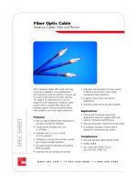
Connector Identification System
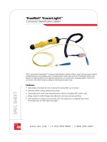
ADC‘s innovative TracerLight
™
Connector Identification System offers a quick and accurate method
of identifying the termination point of optical patch cords. Each end of a TracerLight patch cord
features a flashing light source allowing technicians to visually trace individual patch cords from
one end to the other without pulling or affecting the patch cord.
Features:
• Dramatically minimizes the risk of taking the wrong fiber out of service
• Improves system turnup speed and accuracy
• TracerLight patch cords meet all performance criteria of standard ADC patch cords
• Ideally suited for SAN (Storage Area Network) and cross-connect patching
• 72% reduction in jumper turn-up times and 13% reduction in accidental down-time.
TracerLight pays for itself again and again!
1 0 / 0 6 • 1 0 3 4 7 2 A E
TrueNet
®
TracerLight
™
TrueNet
®
TracerLight
™
Connector Identification System
2
w w w . a d c . c o m • + 1 - 9 5 2 - 9 3 8 - 8 0 8 0 • 1 - 8 0 0 - 3 6 6 - 3 8 9 1
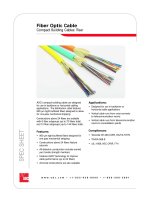
TracerLight
™
Patch Cord
TracerLight
™
optical patch cords feature a
flashing light source (LED) component near each
connector end. The TracerLight power source is
inserted with minimal force into the TracerLight
component on one end of the patch cord. This
causes the LED on each end to begin flashing
rapidly. As a result, the distant end of the patch
cord can be quickly and easily identified without
interruption of service.
Available in any standard length or connector
style, TracerLight patch cords have the same
functions, features, and stringent environmental
requirements as our standard patch cords.
Optical performance of the patch cords is
not affected by the TracerLight components.
TracerLight patch cords are installed in the same
manner as standard patch cords and can be
pulled through ADC‘s FiberGuide
®
Fiber Cable
Management System with ease. Also compatible
with ADC's Next Generation frame with term
block counts up to 144.
TracerLight Patch Cord
Description Ordering Number
1
Multimode Duplex TracerLight Patch Cords
LC-LC with 50/125 multimode laser optimized to 300m, aqua FTL-P/P-KXXXM
LC-SC with 50/125 multimode laser optimized to 300m, aqua FTL-9/P-KXXXM
SC-SC with 50/125 multimode laser optimized to 300m, aqua FTL-9/9-KXXXM
Single Mode Duplex TracerLight Patch Cords
LC-LC Single Mode FTL-C/C-ZXXXM
LC-SC Single Mode FTL-7/C-ZXXXM
SC-SC Single Mode FTL-7/7-ZXXXM
O r d e r i n g I n f o r m a t i o n
Duplex
Tight
Buffered
Fiber
Aramid Yarn
Strength
Members
26 AWG
Copper
Wire (2)
PVC
Jacket
PVC
Jacket
1
XXX – Length in meters. Standard lengths: 001 = 1 meter, 002 = 2 meters, 003 = 3 meters,
005 = 5 meters, 006 = 6 meters, 010 = 10 meters, 015 = 15 meters.
1 0 / 0 6 • 1 0 3 4 7 2 A E
TrueNet
®
TracerLight
™
TrueNet
®
TracerLight
™
Connector Identification System
3
w w w . a d c . c o m • + 1 - 9 5 2 - 9 3 8 - 8 0 8 0 • 1 - 8 0 0 - 3 6 6 - 3 8 9 1
TracerLight Power Source
Description Ordering Number
Power Source FTL-PS
O r d e r i n g I n f o r m a t i o n
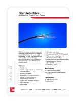
TracerLight
™
Power Source
The compact power source is comprised of a
lightweight, plastic flashlight body featuring two AA
batteries and a printed circuit board (PCB). It provides
approximately 80 hours of continuous service and
features 1-hour auto-off. The end of battery life is
indicated by a slowing of the blink rate.
Specifications
CONNECTORS (Single Mode and Multimode)
Intermateability: TIA/EIA-604-X
SC: FOCIS-3
LC: FOCIS-13*
Connector Body
SC and LC: Plastic
Ferrule: TIA/EIA-604
LC: Zirconia, 1.25
SC: Zirconia, 2.5
Connector Color: GR-326
Singlemode
PC: Blue
APC: Green
Multimode
SC: Black
LC: Beige
(Specifications continued on next page.)
Spec Sheet
Web Site: www.adc.com
From North America, Call Toll Free: 1-800-366-3891 • Outside of North America: +1-952-938-8080
Fax: +1-952-917-3237 • For a listing of ADC’s global sales office locations, please refer to our web site.
ADC Telecommunications, Inc., P.O. Box 1101, Minneapolis, Minnesota USA 55440-1101
Specifications published here are current as of the date of publication of this document. Because we are continuously
improving our products, ADC reserves the right to change specifications without prior notice. At any time, you may
verify product specifications by contacting our headquarters office in Minneapolis. ADC Telecommunications, Inc.
views its patent portfolio as an important corporate asset and vigorously enforces its patents. Products or features
contained herein may be covered by one or more U.S. or foreign patents. An Equal Opportunity Employer
103472AE 10/06 Revision © 2001, 2006 ADC Telecommunications, Inc. All Rights Reserved
Specifications
(cont.)
OPTICAL (Multimode)
Operating Wavelength: 850 and 1300 nm; all tested at both wavelengths
Insertion Loss: 0.3 dB maximum
OPTICAL (Single Mode)
Operating Wavelength: 1310 and 1550 nm; all tests below apply at both wavelengths
Insertion Loss: PC: 0.2 dB maximum
APC: 0.5 dB maximum
Return Loss: PC: 57 dB minimum
APC: 60.5 dB minimum
MECHANICAL (Single Mode and Multimode)
Vibration: GR-326 and FOTP 11; ∆IL < 0.3 dB; 3 planes, 6hrs. 10-55 Hz
Flex Cycling: GR-326 and FOTP 1; ∆IL < 0.3 dB; 100 cycles with 2lbs. load
Twist: GR-326; ∆IL < 0.3 dB; 3lbs; 5 turns, 9 cycles
Mating Durability: FOTP-21A; ∆IL < 0.3 dB; 500 cycles
Tensile Load (Proof): GR-326 and FOTP-6; ∆IL < 0.3 dB; 15 lbs. at 0º and 7.5 lbs. at 90º
Impact: GR-326 and FOTP-2; ∆IL < 0.3 dB; 8 drops from 1 meter (or 1.5 meters)
ENVIRONMENTAL
(Single Mode and Multimode)
Thermal Age: GR-326 and FOTP-4; ∆IL < 0.3 dB; 7 days at 85ºC
Thermal Cycle: GR-326 and FOTP-3A; ∆IL < 0.3 dB; 7 days, -40º to 75ºC, 21 cycles
Humidity Age: GR-326 and FOTP-5; ∆IL < 0.3 dB; 7 days at 75ºC and 95% RH
* Release Pending
Note: 0.3dB max IL @ 850/1300 included with all assemblies.
Note: Now included with all flat polish (UPC) SC and LC singlemode connectors:
• 0.2 dB maximum insertion loss at both 1310 and 1550 nm
• 100% interferometer data
• ±50 nm recession
• <50 micron apex offset
• 10-25 mm radius of curvature