Tài liệu KRONE - White paper - ADSL Service Delivery - 2003 pptx
Bạn đang xem bản rút gọn của tài liệu. Xem và tải ngay bản đầy đủ của tài liệu tại đây (120.82 KB, 8 trang )
1
www.kroneamericas.com
800-775-KRONE
This document may not be reproduced in whole or in part without written permission. © 2003 KRONE, Inc.
White Paper
ADSL Service Delivery
January 21, 2003
A comprehensive look at the challenges of rapidly delivering
ADSL services, keeping up with the subscriber demand, and
controlling operating expenses.
2
www.kroneamericas.com
800-775-KRONE
This document may not be reproduced in whole or in part without written permission. © 2003 KRONE, Inc.
Preface
This white paper analyzes several methods of connecting a Digital Subscriber Line Access
Multiplexer (DSLAM; and splitter) to the outside plant. Analyzed methods include dedicated pair
count, protected jumper, wire-wrap management cabinet and the KRONE Asymmetric Digital
Subscriber Line (ADSL) delivery solution. The analysis primarily focuses on remote equipment
deployments serving lines provisioned on pair-gain or Digital Loop Carrier (DLC) systems.
General
ADSL has emerged as the broadband access technology of choice for most telephony providers
throughout the world. While the initial deployment of DSLAMs rushed to keep pace with
burgeoning customer demand, current conditions require greater consideration of regulatory and
economic factors. Increased scrutiny mandates no less than optimal deployment of capital
spending.
In contrast to dial-tone, DSL is not ubiquitously available. While the location of DSLAM
deployment is critical, the efficiency of the equipment’s interface with the outside plant is
paramount. Slight idiosyncrasies in this interface can result in substantial service interruptions
(both voice and data), underutilization of the DSLAM and dramatic increases in operating
expenses.
ADSL service is unique in that it can be deployed on the existing cable pair, sharing the line with
voice dial-tone. While this equates to cost savings for the operating company and subscriber, it
also comes with some deployment issues. The customer’s dial-tone must be interrupted and then
re-routed through the DSL equipment to be combined with the data. The combined voice and
data must then be connected back to the cable pair.
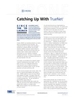
ADSL is deployed in central offices, Controlled Environmental Vaults (CEV), and from Remote
Terminals (RT). No matter where the service is deployed the process to deliver the service is the
same. The Plain Old Telephone Service (POTS) dial-tone must be re-routed into a splitter (filter)
where it is combined with the data service. This combination must then be connected back to the
cable pair.
DSLAM
Fiber or Copper T1
From Central Office
POTS in from RT
ADSL and POTS
Subscriber line to Customer
3
www.kroneamericas.com
800-775-KRONE
This document may not be reproduced in whole or in part without written permission. © 2003 KRONE, Inc.
Remote Terminal
Before looking at each of the ADSL deployment methods this section will review the basic remote
terminal. The trend for several years has been to deploy remote terminal cabinets instead of
building new central offices when network growth is required. Digital Loop Carrier (DLC) systems
have been widely used throughout the network. These cabinets are equipped with active
electronic equipment creating a derived dial-tone. These cabinets can be fed by copper T1
circuits or fiber optics. The DLC remote terminals can be deployed quickly when additional
capacity is needed in the network. In the past, operating companies would have to place more
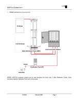
feeder cable to increase capacity. Now, remote terminals increase capacity quickly. The diagram
below shows the basic remote terminal and will be the basis of discussion for each of the ADSL
deployment methods.
Remote Terminal
Pairgain System
Cross box
(Feeder)
(Distribution)
Pedistal
Telephone
NID
Drop
Fiber feed to CO
Existing Remote Terminal
Typical Remote Terminal
Digital Loop Carrier System
Cross Box
4
www.kroneamericas.com
800-775-KRONE
This document may not be reproduced in whole or in part without written permission. © 2003 KRONE, Inc.
Methods of ADSL delivery
The following diagram will be used to illustrate several methods of ADSL delivery.
Remote Terminal
Pairgain System
Cross box
(Feeder)
(Distribution)
Pedistal
Telephone
NID
Drop
Remote Terminal with ADSL
Various methods of ADSL Delivery
ADSL Solution
1.
2.
3.
Computer
Microfilter
Wire Management
Cabinet
Fiber feed
to CO
Connecting a DSLAM to the Outside Plant:
Dedicated Pair Counts Method
Description
This ADSL deployment method dedicates a particular pair count for ADSL in the feeder cable that
leaves the remote terminal. It requires dedicated pairs for the voice inputs and then dedicated
pairs for the combined output. This method provides the capability to address multiple cross
boxes. However each feeder cable would have some pairs dedicated for ADSL. (See item 1 in
above diagram)
Service Delivery
This method requires the technician to access the cross connect cabinet, then identify the
distribution pair that has requested service. The cross connect jumper that is connecting the
distribution pair to the feeder pair must be removed. During this time the customer’s service is
dropped. New jumpers must then be run from the distribution pair binding post to the ADSL
output binding post in the cross box. Then a jumper must be run from the feeder binding post to
the ADSL input binding post. The dial-tone is routed into the DSL solution and then back from the
DSLAM to the cable pair with the voice and data combined.
To disconnect service, the technician must remove the two jumpers that are running to the
DSLAM input/output binding post and run a new jumper between the feeder pair and the
distribution pair. The customer’s service is dropped during this disconnect and re-wire
period.
5
www.kroneamericas.com
800-775-KRONE
This document may not be reproduced in whole or in part without written permission. © 2003 KRONE, Inc.
Connecting a DSLAM to the Outside Plant:
Protected Jumper Method
Description
With this approach, a protection field within the remote terminal is used to gain access to the dial-
tone and re-route into the DSLAM. A custom protector unit is equipped with a 2-pair jumper wire
that exits the rear of the protector module. Inside the RT cabinet a connecting block is added for
the inputs to the DSLAM splitter and the combined outputs. Typically, this is a wire-wrap block
and is cabled to the DSLAM solution. (See items 2 on above diagram)
Service Delivery
To activate service, the technician unplugs the protector module on the selected cable pair. The
customer’s service is dropped during this re-wiring process. The protector with the 2-pair
jumper is inserted into the protector field. The jumper is then routed inside the cabinet to the
ADSL interface terminal block. The technician strips and wire-wraps the ends of the jumper to the
respective voice input and combined output. The completed process activates ADSL service for
the customer.
To disconnect service, the technician removes the protected jumper coil from the protector field
and inserts a standard protector. The customer’s service is dropped during this process.
Connecting a DSLAM to the Outside Plant:
Wire Management Cabinet with Wire-wrap Interface Method
Description
This delivery method utilizes a separate cabinet to handle the ADSL circuit wiring. A separate
cabinet either attaches directly to the remote terminal, or can stand alone on a nearby pad. The
cabinet is equipped with wire-wrap blocks for the ADSL input/output and blocks for the pair-
gain/cable pair appearances. Every one of the dial-tone circuits appear in this special cabinet.
Each of the pair-gain terminal blocks is equipped with small straps that connect through the dial-
tone to the cable pair. Basically the pair-gain and cable pair appearances within the wire
management cabinet are positioned between the dial-tone source and the cross connect box.
(See items 3 on above diagram)
Service Delivery
To deploy service with this method, a technician gains access to this cabinet and removes the
wire-wrap straps from the cable pair requesting service. The customer’s service is dropped
during this step. Next the technician must add a jumper from the pair-gain (dial-tone) to the
ADSL input terminal block and another jumper back to the cable pair block. This re-routes the
dial-tone into the ADSL solution and back to the customer cable pair.
To disconnect service the technician must remove the jumpers from the input and output and
place small wire-wrap straps back into position between the cable pair and the feeder circuit. The
customer’s service is dropped during this operation.