Tài liệu KRONE - White paper - Limitation of RJ21 in Ethernet pptx
Bạn đang xem bản rút gọn của tài liệu. Xem và tải ngay bản đầy đủ của tài liệu tại đây (226.7 KB, 2 trang )
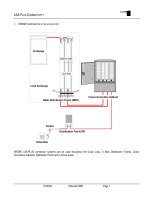
Use of RJ-21 Connectors in 100Base-T
Active Connectivity
KRONE, Inc. has performed numerous site surveys of end-user networks over the past year, and it
has come to our attention that many users are upgrading to new 100Base-T switches that utilize the
RJ-21 connector, also commonly known as a “Telco” connector, or “Amphenol” type. It consists of
a 50 pin connector that accepts 25 pairs of cable simultaneously.
KRONE has not been recommending this type of interface to our customers due to
serious technical limitations of this connector, as described in this paper. All
versions of the RJ-21 that we have seen do not conform to the impedance
matching requirements of KRONE’s TrueNet
TM
system, and consequently can
seriously effect network performance.
Figure 1 shows a TrueNet impedance matched
channel. All components are matched for
optimum performance together, and the distance
plot shows a clean trace centered around a
nominal 100 ohms.
Impedance matching of cabling and components
is critical for efficient data transmission.
Research conducted by KRONE and Anixter
shows that mismatched systems can be
standards-compliant, and still allow frame error
rates approaching
25% of packets sent
! (source-
Anixter).
Figure 2 shows the frequency trace of the channel
shown in Figure 1. The impedance stays tightly
controlled across the entire range of 100Base-T
operation, from approximately 1 to 125 Megahertz.
These charts are displayed to show a baseline for the
comparisons that we will make to the RJ-21 interfaces
that we have seen in the field.
Figure 1: A TrueNet Matched-
Impedance Channel
RJ-21
Figure 2: Frequency Trace
of a TrueNet Channel
KRONE, Inc.
6950 S. Tucson Way, Suite R
Englewood, Colorado 80112
1-800-775-5766
www.kroneamericas.com
www.truenet-system.com
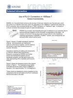
Figure 3 shows a close-up of an RJ21
harness that was connected to a switch at
an actual user site. The impedance spike
here is enormous—far greater than the 100
Ohms +/- 15 called out in the standard
(notice the orange and brown pair actually
fall to 60 ohms!)
When viewed in the frequency domain in
figure 4, we see wild oscillations in the
orange and brown pair, as we might have
predicted from the previous picture. It is
these sorts of oscillations from mismatch that
have the potential to cause such high frame
error rates as previously noted.
Figures 5 and 6 show the same type of
problem with a different RJ-21 assembly at
another site. The effects of the mismatch on
the frequency trace are the same.
The inherent problem with the RJ-21
connector is that it was never designed to run
data. It is referred to as a “telco” connector
for good reason—it’s typically used for
telephone connections, not high frequency
data signals. Several vendors claim to have
upgraded these connectors to Category 5
performance, but no one has reported
meeting the more stringent category 5e
standard, which is now the de-facto minimum
requirement for data (the TIA has dropped
Category 5 from the standard). Furthermore,
the 25 pair cables used in these assemblies is
not category 5e compliant either, nor has the
TIA established a standard for 25 pair cables
above category 5.
Tempting as it may be to install this type of
infrastructure for its high density, KRONE
believes that the performance degradation is
not worth the convenience. The high error
rates this sort of mismatch can cause
contributes to increased troubleshooting,
network drag, and possibly a shorter upgrade
cycle, as a loss of bandwidth due to errors saps
overall network capacity. KRONE
recommends an impedance matched system
using RJ-45 connectors instead.
Figure 3: An RJ-
21 Assembly
Figure 4: An RJ-
21 Assembly
Figure 5: An RJ-
21 Assembly
Figure 6: An RJ-
21 Assembly