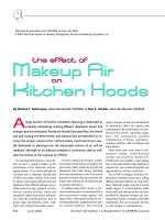
Tài liệu THE EFECT OF MAKEUP AIR ON KITCHEN HOODS ppt
Bạn đang xem bản rút gọn của tài liệu. Xem và tải ngay bản đầy đủ của tài liệu tại đây (1.23 MB, 5 trang )
K18 June 2003 Kitchen Ventilation | A Supplement to ASHRAE Journal
By Richard T. Swierczyna, Associate Member ASHRAE, & Paul A. Sobiski, Associate Member ASHRAE
A
large portion of kitchen ventilation planning is dedicated to
properly exhausting cooking effluent. Appliance layout and
energy input are evaluated, hoods are located and specified, ductwork
size and routing are determined, and exhaust fans are specified to re-
move the proper volume of air. Unfortunately, much less time is usu-
ally dedicated to planning how the exhausted volume of air will be
replaced, although an air balance schedule is commonly used to indi-
cate the source of the makeup air (MUA).
Overlooking MUA delivery system de-
tails can have a negative impact on the
performance of an otherwise well-de-
signed kitchen. Cross drafts and high air
velocities due to improper introduction
of MUA can result in failure of the hood
to capture and contain effluent from the
appliances. This effluent spillage may in-
clude convective heat, products of com-
bustion (carbon dioxide, water and
potentially carbon monoxide), and prod-
ucts from the cooking process, such as
grease vapor and particles, odors, water
vapor, and various hydrocarbon gases.
project focused on how the introduction
of makeup air affects the capture and
containment (C&C) performance of com-
mercial food service ventilation equip-
ment. The investigation included
combinations of hoods, appliances,
cooking conditions, MUA strategies and
other factors.
Three hood types were tested: wall-
mounted canopy, island-mounted
canopy, and proximity (backshelf).
Charbroilers and griddles, representing
heavy-duty and medium-duty appliances
respectively, were tested during idle and
representative cooking conditions.
The six MUA strategies included: dis-
placement ventilation (base case), ceiling
diffuser, front face diffuser, air curtain dif-
fuser, backwall supply, and short-circuit
supply (Figure 1). Certain features of the
hoods and local makeup air devices were
modified to represent designs and con-
figurations found in commercial kitchen
installations, but not necessarily the best
or worst designs or configurations.
Overall commercial kitchen ventila-
tion issues include indoor air quality, fire
prevention, safety, employee comfort and
equipment first costs, energy operating
costs and maintenance costs. This article
presents strategies that can minimize the
impact that makeup air introduction has
on hood performance.
To address these MUA issues, a two-
year research project was sponsored by a
state government energy agency
1
and
large utility. Subsequent testing for sev-
eral manufacturers augmented this pub-
lic research initiative. This research
Reprinted by permission from ASHRAE Journal, July 2003.
© 2003 American Society of Heating, Refrigerating and Air-Conditioning Engineers, Inc.
Kitchen Ventilation | A Supplement to ASHRAE Journal June 2003 K19
‘
Overlooking MUA delivery system
details can have a negative impact
on the performance of an other-
wise well-designed kitchen.
’
To determine which MUA strategy offered the most effec-
tive operation while providing full capture and containment
(C&C), the research team tested the following hypothesis:
If the MUA strategy were to have no effect on exhaust
hood performance (i.e., equivalent to the displacement
ventilation base-case condition), then it would be pos-
sible to replace 100% of the air exhausted through the
makeup air configuration being investigated, while main-
taining C&C.
It was conclusively demonstrated that each of the MUA strat-
egies and specific configurations tested compromised the ex-
haust hood’s ability to completely capture and contain the
thermal plume and/or effluents at higher makeup airflow rates).
Temperature of the locally supplied makeup air also was shown
to effect hood performance as air density impacts the dynamics
of air movement around the hood. Generally, hotter MUA tem-
peratures (e.g., greater than 90°F [32°C]) will affect hood perfor-
mance more adversely than cooler air (e.g., less than 75°F [24°C]).
C
KV System Performance Testing
The phrase “hood capture and containment” is defined in
ASTM F1704-99 Standard Test Method for the Performance
of Commercial Kitchen Ventilation Systems
2
as “the ability of
the hood to capture and contain grease-laden cooking vapors,
convective heat and other products of cooking processes.”
Capture and containment performance testing incorporated
focusing schlieren and shadowgraph visualization systems to
verify capture and containment in accordance with ASTM
F1704-99. These technologies are a major breakthrough for
visualizing thermal and effluent plumes from cooking pro-
cesses. A schlieren system presents a high-contrast image of
turbulent patterns due to the different air densities within the
thermal plume, similar to the effect we see over hot pavement.
With appliances at idle (ready-to-cook) condition, C&C evalu-
ation is a relatively simple and repetitive task. A realistic surro-
gate was needed to produce consistent effluent during cooking
C&C evaluations. Since cooking hamburgers provide peak ef-
fluent production for approximately 10 seconds during a six-
minute cooking session, cooking with hamburgers was used as
a baseline condition for cooking plume simulation.
For charbroilers, the natural gas flow was increased to match
the previously established cooking plume. The cooking plume
simulator for the gas griddle was based on spraying water onto
the hot cooking surface, using a pressure regulator and timed
relay valve for control, and needle valves for fine-tuning.
During baseline displacement ventilation C&C tests, the
exhaust flow rate was reduced until spillage of the thermal
plume was observed. The exhaust flow rate was then increased
in fine increments until full C&C was achieved over the test
condition. The airflow rate at this condition is referred to as the
threshold exhaust airflow rate for complete C&C. These values
provided a baseline case to judge the various MUA strategies.
Evaluating the performance degradation due to cross drafts
required a repeatable and practical disturbance. For this task, a
pedestal-mounted fan was located diagonally from the front
corner of the hood.
For most of the local MUA configurations investigated, the
exhaust airflow rate was set initially to the C&C rate deter-
mined in the baseline displacement MUA test. The local MUA
was then increased (in a balanced room condition) until the
threshold of capture and containment was exceeded (i.e., spill-
age observed). This MUA rate was the airflow rate reported
relative to the displacement exhaust C&C rate as the maxi-
mum percentage of MUA that could be supplied without im-
pacting hood performance.
An exception to the general procedure for local MUA C&C
testing was the ceiling four-way diffuser. Testing was performed
with constant 1,000 cfm (472 L/s) airflow and modulating the
exhaust system to the threshold C&C condition. In addition to
the described protocols, MUA rates were incrementally increased
to determine the marginal increase in exhaust airflow rate. This
procedure led to an exhaust-to-MUA ratio determination and
index of MUA effect. The following discussion presents research
results from the viewpoint of optimizing system performance.
Displacement Diffusers
Displacement ventilation was the baseline for the study be-
cause it provided a uniform, nearly laminar bulk airflow. This
low-velocity bulk airflow has proven optimal for attaining C&C
K20 June 2003 Kitchen Ventilation | A Supplement to ASHRAE Journal
with the lowest exhaust
rate. Therefore, supply-
ing makeup air through
displacement diffusers as
illustrated at right is an
effective strategy for in-
troducing replacement
air. Unfortunately, dis-
placement diffusers re-
quire floor or wall space that is usually at a
premium in the commercial kitchen. A pos-
sible solution may be remote displacement
diffusers (built into a corner) to help distrib-
ute the introduction of makeup air into the
kitchen when transfer air is not viable.
Air Curtain Supply
Most hood manufacturers
recommend limiting the
percentage of MUA sup-
plied through an air curtain
to less than 20% of the
hood’s exhaust flow. At such
low air velocities, an air cur-
tain may enhance C&C de-
pending on design details. However, in the cases
tested, the air curtain was the worst performing
strategy at higher airflows. The negative im-
pact of an air curtain is clearly illustrated above
by the schlieren flow visualization recorded
during a test of a wall-mounted canopy hood
operating over two underfired broilers.
Introducing MUA through an air curtain is a
risky option. An air curtain (by itself or in com-
bination with another pathway) is not recom-
mended, unless velocities are kept to a
minimum and the designer has access to per-
formance data on the specified air curtain con-
figuration. Typical air curtains are easily
adjusted, which could cause cooking effluent
to spill into the kitchen by inadvertently creat-
ing higher than specified discharge velocities.
Short-Circuit Supply (Internal MUA)
Internal MUA hoods were developed as a
strategy to reduce the amount of conditioned
air required by an exhaust system to meet code
requirements. This is accomplished by intro-
ducing a portion of the untempered makeup
air directly into the exhaust hood reservoir. In
cold climates, condensation and cooking sur-
face cooling become undesirable side effects.
The laboratory testing
demonstrated that when
short circuit hoods are op-
erated with excessive inter-
nal MUA, they fail to
capture and contain the
cooking effluent, often
spilling at the back of the
hood (although front spill-
age is observed in the figure at right). If, how-
ever, the specified exhaust rate is higher than
the threshold for C&C in an exhaust-only con-
figuration, the short-circuit airflow rate can
be increased accordingly, creating a condi-
tion of apparent benefit on a percentage ba-
sis. For the short circuit configuration tested,
the average MUA rate that could be introduced
without causing spillage was 15% of the
threshold C&C exhaust rate.
Front Face Supply
Supplying air through
the front face of the hood
is a configuration recom-
mended by many hood
manufacturers. In theory,
air exits the front face unit
horizontally into the
kitchen space. However, a
front face discharge with
louvers or perforated face can perform poorly,
if its design does not consider discharge air
velocity and direction. The figure above repre-
sents a poorly designed perforated face supply,
which negatively affected this hood’s capture
performance in the same fashion as an air cur-
tain or four-way diffuser.
To improve front face performance, internal
baffling and/or a double layer of perforated
plates may be used to improve the uniformity
of airflow. In addition, greater distance be-
tween the lower capture edge of the hood and
the bottom of the face discharge area may de-
crease the tendency of the MUA supply to
interfere with hood capture and containment.
In general, face discharge velocities should
not exceed 150 fpm (0.75 m/s) and should
exit the front face in a horizontal direction.
Perforated Perimeter Supply
Perforated perimeter supply is similar to a
front face supply, but the air is directed down-
Figure 1: Types of MUA sup-
ply integrated with the hood.
Displacement
diffusers
Impact of air
curtain
Excessive in-
ternal MUA
Poorly designed
perforated front
face supply
Kitchen Ventilation | A Supplement to ASHRAE Journal June 2003 K21
ward (see figure at right) toward the hood
capture area. This may be advantageous un-
der some conditions, since the air is directed
downward into the hood capture zone.
For proper hood performance, discharge
velocities should not exceed 150 fpm (0.75
m/s) from any section of the diffuser and
the distance to lower edge of the hood
should be no less than 18 in. (0.5 m). If the
air is not introduced in this manner, the system begins to act like
an air curtain. An increase in the plenum discharge area lowers
the velocity for a given flow of MUA and reduces the chance of
it affecting C&C. If the perforated perimeter supply is extended
along the sides of the hood as well as the front, the increased
area will permit proportionally more MUA to be supplied.
Four-Way Ceiling Diffusers
Four-way diffusers located close to
kitchen exhaust hoods (see figure at
right) can have a detrimental effect on
hood performance, particularly when
the flow through the diffuser ap-
proaches its design limit.
Perforated plate ceiling diffusers can
be used in the vicinity of the hood, and a greater number of
ceiling diffusers reduce air velocities for a given supply rate.
To help ensure proper hood performance, air from a diffuser
within the vicinity of the hood should not be directed toward
the hood. If ceiling supplied air must be directed toward a
hood, the air discharge velocity at the diffuser face should be
set at a design value such that the terminal velocity does not
exceed 50 fpm (0.25 m/s) at the edge of the hood capture area.
Backwall Supply
The lab testing demonstrated that
the backwall supply can be an effec-
tive strategy for introducing MUA (see
figure at right). For the backwall sup-
ply tested with a canopy hood, the av-
erage MUA rate that could be
introduced without causing spillage
was 46% of the threshold C&C exhaust rate.
To help ensure proper performance, the discharge of the
backwall supply should be at least 12 in. (0.3 m) below the
cooking surfaces of the appliances to prevent the relatively
high velocity introduction of MUA from interfering with
gas burners and pilot lights. Backwall plenums with larger
discharge areas may provide increased airflow rates as
long as discharge velocities remain below maximum thresh-
olds. Ideally, the quantity of air introduced through the
backwall supply should be no more than 60% of the hood’s
exhaust flow.
Other Factors that Influence Hood Performance
Hood Style. Wall-mounted canopy hoods function effectively
with a lower exhaust flow rate than single-island hoods. Island
canopy hoods are more sensitive to MUA supply and cross drafts
than wall-mounted canopy hoods. Proximity hoods exhibit lower
C&C exhaust rates, and in some cases, perform the same job at
one-third of the exhaust rate required by a wall-mounted hood.
Cross Drafts. Cross drafts have a detrimental effect on all
hood/appliance combinations, and adversely affect island
canopy hoods more than wall-mounted canopy hoods. A fan in
a kitchen, especially pointing at the cooking area, severely de-
grades hood performance and may make capture impossible.
Cross drafts required at least a 37% increase in exhaust flow rate
and in some cases C&C could not be achieved with a 235%
increase in exhaust rate. Cross drafts can result from portable
fans, movement in the kitchen, or an unbalanced HVAC system.
Side Panels and Overhang. Side (or end) panels permit a
reduced exhaust rate in most cases, as they direct the replace-
ment airflow to the front of the hood. The installation of side
panels improved C&C performance for static conditions an av-
erage of 10% to 15% and up to 35% for dynamic (cross-draft)
conditions. They are a relatively inexpensive way to achieve
C&C performance and reduce the total exhaust rate. Partial side
panels are able to provide virtually the same benefit as full
panels. One of the greatest benefits of side panels is to mitigate
the negative effect of cross drafts. An increase in overhang may
increase the ability to contain large volume surges from cook-
ing processes that use convection and combination ovens, steam-
ers and pressure fryers, although for unlisted hoods this may
mean an increase in the code-required exhaust rate.
MUA Strategy and C&C Exhaust Rate
What was not anticipated during the design of the study was
how sensitive the C&C threshold would be to the local intro-
duction of MUA. Spill conditions often were observed when as
little as 10% of the exhaust rate was supplied by a given MUA
strategy. Figure 2 shows a generic trend for changes in exhaust
airflow rate as MUA flow rate increases for a given hood/MUA
system. In this generic graph, the C&C exhaust flow rate is 3,000
cfm (1400 L/s) with no locally supplied MUA. For local MUA
up to 500 cfm (236 L/s), the system did not require an increase
in the exhaust rate, as represented by the horizontal part of the
curve. When the MUA was increased beyond the 500 cfm (236
L/s), the exhaust rate had to increase to maintain C&C. For this
particular hood/MUA system, every 1 cfm (0.47 L/s) increase in
MUA required a 0.75 cfm (0.35 L/s) increase in exhaust rate. In
the better performing MUA strategies, more local MUA can be
introduced without increasing the exhaust rate to maintain C&C.
Conclusions
The primary recommendation to reduce the impact that lo-
cally supplied MUA may have on hood performance is to mini-
Perforated peri-
meter supply
Backwall supply
Four-way diffusers
K22 June 2003 Kitchen Ventilation | A Supplement to ASHRAE Journal
mize the velocity (fpm) of the makeup air as it is introduced near
the hood. This can be accomplished by minimizing the volume
(cfm) of makeup air through any single distribution system, by
maximizing the area of the diffusers through which the MUA is
supplied, or by distributing through multiple pathways.
Makeup air that is supplied through displacement ventila-
tion diffusers, perforated diffusers located in the ceiling as far
as possible from the hood, or as transfer air from the dining
room generally works well if air velocities approaching the
hood are less than 75 fpm (0.25 m/s). However, makeup air
introduced close to an exhaust hood has the potential to inter-
fere with the hood’s ability to capture and contain. The chances
of makeup air affecting hood performance increases as the
percentage of the locally supplied MUA (relative to the total
exhaust) is increased. In fact, the 80% rule-of-thumb for sizing
airflow through an MUA system may be a recipe for trouble.
The first step to reducing the MUA requirement is to lower the
design exhaust rate. This can be accomplished by prudent selec-
tion and application of UL-listed hoods.
3
The use of side and/or
back panels on canopy hoods to increase effectiveness, miti-
gate cross drafts and reduce heat gain is highly recommended.
The next step in reducing MUA flow is to take credit for
outside air that must be supplied by the HVAC system to meet
code requirements for ventilating the dining room. Depend-
ing on the architectural layout, it may be practical to transfer
most of this air to the kitchen. Although this may contradict
past practice, the hood performance will be superior and the
kitchen environment will benefit from the contribution of the
conditioned dining room air.
References
1. Brohard, G., et al. 2003. Makeup Air Effects on Kitchen Exhaust
Hood Performance. California Energy Commission, Sacramento, Calif.
2. ASTM. 1999. Test Method for Performance of Commercial Kitchen
Ventilation Systems. Standard F 1704-99. American Society for Testing
and Materials, West Conshohocken, Pa.
3. 1999 ASHRAE Handbook—HVAC Applications. Chapter 30,
Kitchen Ventilation.
Richard T. Swierczyna is the lab operations manager and
Paul A. Sobiski is a research engineer at Architectural Energy
in Wood Dale, Ill.
6,500
5,500
4,500
3,500
2,500
1,500
500
0
Exhaust Airflow Rate (cfm)
0 1,000 2,000 3,000 4,000 5,000
Makeup Airflow Rate (cfm)
MUA
Introduction
with No Effect
on C&C
C&C for Exhaust Only Condition
MUA Has More of an Effect on Hood Performance
MUA Has Less of an
Effect on Hood
Performance
Figure 2: Potential impact of MUA on exhaust flow rates.
Advertisement in the print edition formerly in this space.