Tài liệu SONEPLEX DS3 REMOTE CONTROL SYSTEM doc
Bạn đang xem bản rút gọn của tài liệu. Xem và tải ngay bản đầy đủ của tài liệu tại đây (120.57 KB, 6 trang )
S
ONEPLEX
®
DS3 R
EMOTE
C
ONTROL
S
YSTEM
The Soneplex DS3 Remote Control System provides for centralized manage-
ment of up to seven remotely located Soneplex Broadband Systems. By using
an existing overhead channel in DS3 links, provisioning, monitoring, and
alarm information can be easily attained without the need for a secondary
communications network. This channel is used to transport TL1, TBOS, or
menu messages from each remote Soneplex Broadband System to a network
Operating System or a craft terminal.
ADC's Soneplex system is the lowest total cost solution for
carriers to grow their T1-based business services. Focused
on providing flexible, end-to-end solutions, the Soneplex
system saves carriers money on T1-based services over cop-
per or fiber, using HDSL, ADSL, traditional T1 repeater or
optical DS2 technology in a single platform. From opera-
tions, maintenance, provisioning and high-speed back-
bone connections to central office space and cabling, the
Soneplex system is designed to take costs out of today's T1
delivery approach, adding profit to your bottom line.
FEATURES
• Provides visibility and control of seven remote Soneplex Broadband
systems, supporting up to 196 T1 circuits
• Uses embedded DS3 communications channel instead of usable com-
munications bandwidth or an overlay network
• TBOS and TL1 support allow proactive maintenance of Soneplex by
embedded OSS's
The Soneplex System
from ADC. The T1/E1
Service Delivery Experts
21/98
409
Soneplex
®
DS3 Remote Control System
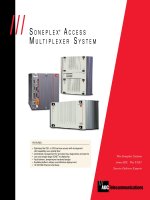
The Soneplex DS3 Remote Control System provides an embedded DS3 communication
channel between a remote Soneplex Broadband System and a Communications Access
Module in the central office. This channel is used for remote alarm reporting, perfor-
mance monitoring, and provisioning of up to 28 DS1 circuits on a Soneplex Broadband
System at the remote site. A single, centrally located DS3 Remote Control System can
support up to seven remote broadband systems, and eliminates the costs of multiplexers,
cross-connect panels, and overlay networks.
At the central office, data from up to seven remote sites is transported over a TL1/TBOS
network to the control center. This allows cost-effective, continuous monitoring and
proactive response to circuit problems, often before they impact users. This is particu-
larly important when DS1 service level has been guaranteed.
Description
Application
DS3
DS3
DS3
Soneplex
Broadband
28 - T1s
7
DS3
Soneplex
Broadband
28 - T1s
1
DS3
Soneplex
Broadband
28 - T1s
2
DS3
D
C
S
C
A
M
(W)
C
A
M
(P)
C
A
M
(W)
C
A
M
(P)
C
A
M
(W)
C
A
M
(P)
A
P
U
TB0S
SONET
MUX
SONET
MUX
SONET
MUX
SONET
MUX
CRAFT
12
DS3
7
ALARM
SONET
TRANSPORT
TL1
Operations
Support
Systems
31/98
409
Soneplex
®
DS3 Remote Control System
System
Overview
The Soneplex DS3 Remote Control System consists of the following components:
• Communications Channel Access Chassis (CCAC)
• Up to 14 DS3 Communications Access Modules
• Alarm Processor Unit (APU)
• At least one Soneplex Broadband Chassis at a remote site equipped with a Remote
Communications Module (RCM)
Communications
Channel Access
Chassis
Dimensions (HxWxD): 6" x 23" x 12" (15.24 x 58.42 x 30.48 cm)
Weight: 15 lbs (6.8 kg)
Chassis Configuration: 7 CAM modules unprotected
14 CAM modules protected, 1 APU
Chassis Mounting: 23" WECO or EIA mounting
2" or 5" (5.08 or 12.7 cm) recess
Power: Nominal input; -48 VDC (-42.5 to -56.5
voltage range)
Power Dissipation: Approximately 7.5 watts maximum
Operating Temperature: 0°C to 50°C
Specifications
The Communications Channel
Access Chassis mounts in the
central office in a standard relay
rack. The chassis is 6" high and 23"
wide (15.24 x 58.42 cm) and sup-
ports up to 14 DS3 Communications
Access Modules and one Alarm
Processor Unit. The chassis features
a removable hinged front cover for
easy access to the modules and
adjustable mounting brackets for 2"
or 5" (5.08 or 12.7 cm) recess
mounting.
41/98
409
Soneplex
®
DS3 Remote Control System
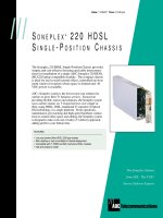
Communications
Channel Access
Module
The DS3 Communications Access Module
(CAM) provides remote access, performance
monitoring, alarm and maintenance
capability to one remote Soneplex Broad-
band System. The CAM operates in either a
protected or nonprotected configuration
within the Communications Channel Access
Chassis. The CAM communicates via the
overhead of the DS3 signal to the Remote
Communications Module (RCM) which is
deployed in the Soneplex Broadband Chassis
at a remote location. The front panel
features LED indicators, control switches
and a DB9 connector for circuit status and
local craft interface support.
Power Consumption:
Operating Temperature:
Dimensions (HxWxD):
Weight:
7.5 watts
0°C to 50°C
4.4" x 14" x 9.2" (11.18 x 35.56 x 23.37 cm)
.75 lbs (.34 kg)
Specifications
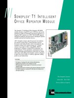
System Overview
Alarm Processor
Unit
Specifications
The Alarm Processor Unit (APU) provides basic
alarm reporting and performance monitoring
for the Soneplex Communications Channel
Access Chassis. The APU module contains
chassis alarm relays, alarm cut-off (ACO) and
chassis power monitoring circuitry. The APU
reports critical, major and minor alarms via
front panel LED indicators. An alarm cut-off
feature can be provisioned for audible alarms.
The APU also supports up to eight housekeep-
ing alarm inputs.
Power Consumption:
Operating Temperature:
Dimensions (HxWxD):
Weight:
7.5 watts maximum
40°C to 65°C
4.875" x .6875" x 9.75" (12.38 x 1.75 x 24.76 cm)
.556 lbs (.252 kg)
51/98
409
Soneplex
®
DS3 Remote Control System
User Interfaces
The Soneplex Broadband System provides integrated circuit monitoring and
maintenance, either remotely or locally, through a variety of interfaces includ-
ing craft, TBOS and TL1. The Soneplex DS3 Remote Control System accesses
remotely located TBOS, TL1 and craft interface functions through a selected C-
Bit DS3 overhead channel. This C-Bit channel is connected to the MPU in the
remote Soneplex Broadband Chassis as a 28.2 Kbit HDLC serial data link.
Interfaces
• MPU Craft Interface: A menu driven control system that is part of the Soneplex Broadband
Chassis MPU software
- Accessed through the DB9 connector on the front of the Communications Access Module
using a VT100 terminal or through a personal computer with a communication
software program
- User IDs and passwords provide system security
• Telemetry Byte Oriented Serial (TBOS) Interface
- Provides communication status, alarm, provisioning and maintenance information between
E2A-Alarm Processing Remote (APR) equipment and remote Soneplex Broadband Systems
- Meets the requirements of AT&T CB-149 Section B2
• Transaction Language (TL1) Interface
- Provides communication status, alarm, provisioning and maintenance information between
Operations Support System and one remote Soneplex Broadband Chassis
• Local Craft Interface: A menu driven control system that is part of the Communications
Access Module software
- Accessed through the DB9 connector on the front of the Communications Access Module
using a VT100 terminal or through a personal computer with a communications
software program
- Used to provision and monitor the Communications Access Module
The Remote Communication Module (RCM) plugs into the Soneplex Broadband
Chassis at the remote location. This module provides a direct communication
link between the Main Processor Unit (MPU) and the DS3 MUX module for
insertion and extraction of the OAM&P information into the C-Bit parity of the
DS3 overhead.
System Overview
Remote
Communication
Module
Specifications
Operating Temperature: -40°C to 65°C
Dimensions (HxWxD): 9.27" x 0.7" x 9.28" (23.55 x 1.78 x 23.57 cm)
Weight: .5 lb (.26 kg)