Tài liệu Lab 5.1.13b Building a Switch-based Network pptx
Bạn đang xem bản rút gọn của tài liệu. Xem và tải ngay bản đầy đủ của tài liệu tại đây (268.4 KB, 4 trang )
1 - 4 CCNA 1: Networking Basics v 3.0 - Lab 5.1.13b Copyright 2003, Cisco Systems, Inc.
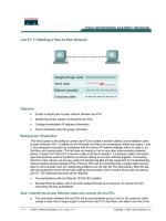
Lab 5.1.13b Building a Switch-based Network
Objective
• Create a simple network with two PCs using a switch
• Identify the proper cable to connect the PCs to the switch
• Configure workstation IP address information
• Test connectivity using the ping command
Background / Preparation
This lab focuses on the ability to connect two PCs to create a simple 2-workstation, switch-based
Ethernet LAN. A switch is a networking concentration device sometimes referred to as a multiport
bridge. Switches are relatively inexpensive and easy to install. When operating in full duplex mode,
they provide dedicated bandwidth to workstations and eliminate collisions by creating 2-workstation
microsegments between ports. They are appropriate for small to large LANs with moderate to heavy
traffic.
In addition to the physical and data link connections, which are Layers 1 and 2, the computers must
also be configured with the correct IP network settings, which is Layer 3, so that they can
communicate. Since this lab uses a switch, a basic CAT 5/5e UTP straight-through cable is needed
to connect each PC to the switch. This is referred to as a patch cable or horizontal cabling, which is
used to connect workstations and a typical LAN. Start this lab with the equipment turned off and with
cabling disconnected. Work in teams of two with one person per PC. The following resources will be
required:
2 - 4 CCNA 1: Networking Basics v 3.0 - Lab 5.1.13b Copyright 2003, Cisco Systems, Inc.
• Two workstations with an Ethernet 10/100 NIC installed
• Ethernet 10BaseT or Fast Ethernet switch
• Several Ethernet cables, which are straight-through and crossover, to choose from for
connecting the two workstations
Step 1 Identify the proper Ethernet cable and connect the two PCs to the switch
a. The connection between the two PCs and the switch will be accomplished using a cat 5 or 5e
straight-through patch cable. Locate two cables that are long enough to reach from each PC to
the switch. Attach one end to the NIC and the other end to a port on the switch. Be sure to
examine the cable ends carefully and select only a straight-through cable.
b. What kind of cable is required to connect from NIC to switch?
_________________________
c. What is the category rating of the cable?
________________________________________
d. What is the AWG wire size designation of the cable?
_______________________________
Step 2 Verify the physical connection
a. Plug in and turn on the computers. To verify the computer connections, insure that the link lights
on the both PC NICs and the switch interfaces are lit. Are all link lights lit?
________________
Step 3 Access the IP settings window
Note: Be sure to write down the existing IP settings, so that they can be restored at the end
of the lab. These include IP address, subnet mask, default gateway, and DNS servers. If the
workstation is a DHCP client, it is not necessary to record this information.
Windows 95 / 98 / Me/ users should do the following:
• Click on Start > Settings > Control Panel and then click the Network icon.
• Select the TCP/IP protocol icon that is associated with the NIC in this PC and click on
Properties.
• Click on the IP Address tab and the Gateway tab.
Windows NT / 2000 users should do the following:
• Click on Start > Settings > Control Panel and then click the Network icon.
• Click on the Protocols tab and select the TCP/IP protocol icon that is associated with the NIC in
this PC.
• Click on Properties and click on Specify an IP address.
Windows XP users should do the following:
• Click on Start > Control Panel and then click the Network Connection icon.
• Select the Local Area Network Connection and click on Change settings of this connection.
See the example below:
3 - 4 CCNA 1: Networking Basics v 3.0 - Lab 5.1.13b Copyright 2003, Cisco Systems, Inc.
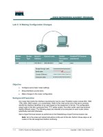
Step 4 Configure TCP/IP settings for the two PCs
a. Set the IP address information for each PC according to the information in the table.
b. Note that the default gateway IP address is not required, since these computers are directly
connected. The default Gateway is only required on local area networks that are connected to a
router.
Computer IP Address Subnet mask Default Gateway
PC – A 192.168.1.1 255.255.255.0 Not Required
PC – B 192.168.1.2 255.255.255.0 Not Required
Step 5 Access the Command or MS-DOS prompt
a. Use the Start menu to open the Command Prompt (MS-DOS-like) window:
Windows 95 / 98 / Me users should do the following:
Start > Programs > MS-DOS Prompt
Windows NT / 2000 users should do the following:
Start > Programs > Command Prompt
Windows XP users should do the following:
Start > Programs > Accessories > Command Prompt
4 - 4 CCNA 1: Networking Basics v 3.0 - Lab 5.1.13b Copyright 2003, Cisco Systems, Inc.
Step 6 Verify that the PCs can communicate
a. Test connectivity from one PC to the other through the switch by pinging the IP address of the
opposite computer. Use the following command at the command prompt.
C:>ping 192.168.1.1 (or 192.168.1.2)
b. Look for results similar to those shown below. If not, check the PC connections and New York
TCP/IP settings for both PCs. What was the ping result?
__________________________________________________________________________
__________________________________________________________________________
Step 7 Confirm the TCP/IP network settings
Windows 95 / 98 / Me users should do the following:
a. Run the winipcfg command from the MS-DOS Prompt. Record the results.
__________________________________________________________________________
Windows NT / 2000 / XP users should do the following:
b. Run the ipconfig command from the Command Prompt. Record the results.
__________________________________________________________________________
Step 8 Restore the PCs to their original IP settings, disconnect the equipment, and store the
cables