Tài liệu Tài liệu Diezel 1410 P9 docx
Bạn đang xem bản rút gọn của tài liệu. Xem và tải ngay bản đầy đủ của tài liệu tại đây (202.93 KB, 19 trang )
9
ENGINE PERFORMANCE AND OPERATION
A. COMBUSTION, AND EFFICIENCY
9A1. Combustion. Engine efficiency is
a comparison of the amount of power
developed by an engine to the energy
input as measured by the heating value
of the fuel consumed. In order to
understand the various factors
responsible for differences in engine
efficiency, it is necessary to have some
knowledge of the combustion process
which takes place in the engine.
In the diesel engine, ignition of the fuel
is accomplished by the heat of
compression alone. To support
combustion, air is required.
Approximately 14 pounds of air are
required for the combustion of 1 pound
of fuel oil. However, to insure complete
combustion of the fuel, an excess
amount of air is always supplied to the
cylinders. The ratio of the amount of air
supplied to the quantity of fuel injected
during each power stroke is called the
air-fuel ratio and is an important factor
in the operation of any internal-
combustion engine. When the engine is
operating at light loads there is a, large
excess of air present, and even when
the engine is overloaded, there is an
excess of air over the minimum
required for complete combustion.
The injected fuel must be divided into
small particles, usually by mechanical
atomization, as it is sprayed or injected
into the combustion chamber. It is
imperative that each of the small
particles be completely surrounded by
sufficient air to effect complete
combustion of the fuel. To accomplish
this, the air in the cylinder must be in
motion with good fuel atomization,
combined with penetration and
distribution. In mechanical injection
engines this is accomplished by forcing
scavenging air into the cylinder with a
whirling motion to create the necessary
turbulence. This is usually done, in the
2-cycle engine, by shaping the intake
air ports, or by casting them so that
1. The fuel must enter the cylinder at the,
proper time. That is, the fuel injection
valve must open and close in correct
relation to the position of the piston.
2. The fuel must enter the cylinder in a
fine mist or fog.
3. The fuel must mix thoroughly with the
air that supports its combustion.
4. Sufficient air must be present to assure
complete combustion.
5. The temperature of compression must
be sufficient to ignite the fuel.
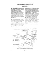
Figure 9-1 is a reproduction of a
pressure-time diagram of a mechanical
injection engine. The lower curvy part of
which is a dotted line, is the curve of
compression and expansion when no fuel
is injected. At A the injection valve
opens, fuel enters the combustion
chamber and ignition occurs at B. The
pressure from A to B should fall slightly
below the compression curve without
fuel due to absorption of heat by the fuel
from the air. The period from A to B is
the ignition delay. From B the pressure
rises rapidly until it reaches a maximum
at C. This maximum, in some instances,
may occur at top dead center. At D the
injection valve closes, the fuel is cut off,
but burning of the fuel continues to some
undetermined point along the expansion
stroke.
The height of the diagram from B to C is
called the firing pressure rise and the
slope of the curve between these two
points is the rate at which the fuel is
burned.
Poor combustion of the fuel is usually
indicated by a smoky exhaust, but some
smoke may be the result of burning
lubricating oil that has passed the rings
into the combustion chamber. Incomplete
combustion is indicated by black smoke,
their centers are slightly tangential to
the axis of the cylinder bore.
Before proceeding with the study of the
combustion process, the conditions
considered essential to good
combustion should be reviewed:
or if the fuel is not igniting, it may appear
as blue smoke. Immediately after starting
an engine, when running at light loads or
at overloads, or when changing from one
load to another, smoke is likely to
appear.
A smoky exhaust from the engine does
not indicate whether one or all the
cylinders are
174
Figure 9-1. Pressure-time diagram of combustion process.
causing it A black-smoking cylinder
usually shows a higher exhaust
temperature which can be observed
from pyrometers installed in the
individual exhaust lines from the
cylinders. Opening the indicator cock
on each cylinder to observe the color of
the exhaust is another check. Still
another method is cutting off the fuel
supply to one cylinder at a time to see
what effect it has on the engine
exhaust. This latter should never be
done when the engine is operating at
full load as overloading of the other
cylinders will result if the engine is
governor controlled.
9A2. Engine losses. It is obvious that
not all of the heat content of a fuel can
be transferred into useful work during
the combustion process. The many
different losses that take place in the
transformation of heat energy into work
may be divided into two classes,
thermodynamic and mechanical. The
radiation and convection to the
surrounding air.
2. Heat rejected and lost to the
atmosphere in the exhaust.
3. Inefficient combustion or lack of
perfect combustion.
A loss due to imperfect or incomplete
combustion is an important item, because
such losses have a serious effect on the
power that can be developed in the
cylinder as shown by the pressure-
volume diagram or indicator card.
Complete combustion is not possible in
the short time permitted in modern
engine design. However, these losses
may be kept to a minimum if the engine
is kept adjusted to the proper operating
condition. Incomplete combustion can
frequently be detected by watching
exhaust temperatures, noting the exhaust
color, and being alert for unusual noises
net useful work delivered by an engine
is the result obtained by deducting the
total losses from the heat energy input.
Thermodynamic losses are caused by:
1. Loss to the cooling system and losses
by
in the engine.
Heat energy losses from both the cooling
water systems and lubricating oil system
are always present. Some heat is
conducted through the engine parts and
radiated to the atmosphere or picked up
by the surrounding air by convection.
The effect of these losses varies
according to the part of the cycle in
which they occur. The
175
heat appearing in the jacket cooling
water is not a true measure of cooling
loss because this heat includes:
1. Heat losses to jackets during
compression, combustion, and
expansion phases of the working cycle.
2. Heat losses during the exhaust
stroke.
3. Heat losses absorbed by the walls of
the exhaust passages.
4. Heat generated by piston friction on
cylinder walls.
Heat losses to the atmosphere through
the exhaust are inevitable because the
engine cylinder must be cleared of the
still hot exhaust gases before another
fresh air charge can be introduced and
another power stroke begun. The heat
lost to the exhaust is determined by the
temperature within the cylinder when
exhaust begins. It depends upon the
amount of fuel injected and the weight
of air compressed within the cylinder.
Improper timing of the exhaust valves,
whether early or late, will result in
increased heat losses. If early, the valve
releases the pressure in the cylinder
before all the available work is
obtained; if late, the necessary amount
of air for complete combustion of the
next charge cannot be realized,
although a small amount of additional
work may be obtained. The timing of
the exhaust valve is a compromise, the
best possible position of opening and
closing being determined by the engine
Figure 9-2. Heat balance for a diesel
engine.
pumping losses caused by operation of
water pumps, lubricating oil pumps, and
scavenging air blowers, power required
to operate valves, and so forth. Friction
losses cannot be eliminated, but they can
be kept at a minimum by maintaining the
engine in its best mechanical condition.
Bearings, pistons, and piston rings should
be properly installed and fitted, shafts
must be in alignment, and lubricating and
cooling systems should be at their highest
operating efficiency.
9A3. Compression ratio and
efficiencies. a. Compression ratio. The
term compression ratio is used quite
extensively in connection with engine
performance and various types of
efficiencies. It may be defined as the
ratio of the total volume of a cylinder to
the clearance volume of the cylinder. It
may be best explained by reference to the
designer. It is essential that the valve be
tight and properly timed in order to
maintain the loss to the exhaust at a
minimum. This is also true for air inlet
valve setting on 4-cycle type engines.
If an indicator card is taken of a diesel
engine cylinder, it is possible to
calculate the horsepower developed
within the cylinder. This calculation
does not take into account the power
loss resulting from mechanical or
friction losses, as will be discussed
later, but it reflects the actual work
produced within the cylinder.
Mechanical losses are of several kinds,
not all of them present in every engine.
The sum total of these mechanical
losses deducted from the indicated
horsepower developed in the cylinders
will give the brake horsepower finally
delivered as useful work by the engine.
These mechanical or friction losses
include bearing friction, piston and
piston ring friction, and
pressure-volume indicator card of a
diesel cylinder. In Figure 9-3, the volume
is reduced from square root(C) + square
root(D) to square root(C) during
compression. The compression ratio is
then equal to
(square root(C) + square root(D))/square
root(C)
176
Figure 9-3. Compression ratio.
Compression ratio influences the
thermal efficiency of an engine.
Theoretically the thermal efficiency
increases as the compression ratio is
increased. The minimum value of a
diesel engine compression ratio is
determined by the compression
required for starting, which, to large
extent is dependent on the type of fuel
used. The maximum value of the
compression ratio is not limited by the
the fuel would fire or detonate before the
piston could reach the correct firing
position.
The temperature-entropy (T-S) diagram
of any particular cycle indicates the
amount of heat input and the amount of
heat rejected. For example, in Figure 9-4,
the T-S diagram of a modified diesel
cycle, the heat input is represented by the
area FBDG and the heat rejected to the
exhaust by the area FAEG. The heat
represented in doing useful work is
represented by the difference between
these two, or area ABDE. The efficiency
of the cycle can then be expressed as
(H
1
-H
2
)/H
1
where H
1
is the heat input
along lines BC and CD (the lines
representing the constant volume and
constant pressure combustion), and H
2
is
the heat rejected along line EA (the line
representing the constant volume
exhaust). Since heat and temperature are
proportional to each other, the cycle
efficiency is actually computed from
measurements made of the temperature.
fuel used but is limited by the strength
of the parts of the engine and the
allowable engine wgt/bhp output.
b. Cycle efficiency. The efficiency of
any cycle is equal to the output divided
by the input. The diesel cycle shows
one of the highest efficiencies of any
engine yet built because of the higher
compression ratio carried and because
of the fact that combustion starts at a
higher temperature. In other words, the
heat input is at a higher average
temperature. Theoretically, the gasoline
engine using the Otto or constant
volume cycle would be more efficient
than the diesel if it could use
compression ratios as high as the latter.
The gasoline engine operating on the
Otto cycle cannot use a compression
ratio comparable to the diesel engine
due to the fact that the fuel and air are
drawn in together and compressed. If
high compression ratios were used,
The specific heat of the mixture in the
cylinder is either known or assumed, and
when combined with the temperature, the
heat content can be calculated at any
instant. Thus, it is seen that temperature
is a measure of heat, and that the heat is
proportional to the temperature of the
gas.
c. Volumetric efficiency. The volumetric
efficiency of an engine is the ratio of the
volume that would be occupied by the air
charge at atmospheric temperature and
pressure to the cylinder displacement (the
product of the
Figure 9-4. Temperature-entropy
diagram of modified diesel cycle.
177
area of the bore times the stroke of the
piston). The volumetric efficiency
determines the amount of air available
for combustion of the fuel, and hence
influences the maximum power output
of the engine.
Volumetric efficiency is actually the
completeness of filling of the cylinder
with fresh air at atmospheric pressure.
The volumetric efficiency of an engine
may be increased by enlarging the areas
of intake and exhaust valves or ports,
and by having all valves properly timed
so that as much air as possible will
enter the cylinders. Since any burned
gases will reduce the charge of fresh
air, the supercharging effect gained by
early closing of the exhaust valves or
ports will reduce the volumetric
efficiency. In some engines, the
volumetric efficiency is also increased
by using special apparatus to utilize air
at 2 to 3 psi over the atmospheric
pressure. This procedure is commonly
calculated as previously explained, the
indicated thermal efficiency can be
computed.
Indicated thermal efficiency =
(Indicated hp X 42.42 Btu per minute per
hp) / (Rate of heat input of fuel in Btu per
minute) X 100 percent
In like manner the over-all thermal
efficiency can be found from the brake
horsepower or the actual power available
at the engine shaft.*
Over-all thermal efficiency =
Brake horsepower / Heat input of fuel X
100 percent
e. Mechanical efficiency. The mechanical
losses in an engine decrease the
efficiency of the engine and represent the
skill with which the engine parts were
designed as well as the skill with which
the operator maintains the engine. As
previously stated, the brake horsepower
called supercharging.
d. Thermal efficiency. Thermal
efficiency may be regarded as a
measure of the efficiency and
completeness of combustion of the
injected fuel. Thermal efficiencies are
generally considered as being of two
kinds, indicated thermal efficiency and
over-all thermal efficiency.
If all the potential heat in the fuel were
delivered as work, the thermal
efficiency would be 100 percent. This
is not possible in practice, of course. To
determine the values of the above
efficiencies the amount of fuel injected
is known, and from its heating value, or
Btu per pound, the total heat content of
the injected fuel can be found. From the
mechanical equivalent of heat (778
foot-pounds are equal to 1 Btu), the
number of foot-pounds of work
contained in the fuel can be computed.
If the amount of fuel injected is
measured over a period of time, the rate
at which the heat is put into the engine
can be converted into potential power.
Then, if the indicated horsepower
developed by the engine is
is equal to the indicated horsepower
minus the mechanical losses. The ratio of
brake horsepower to indicated
horsepower, then, is the mechanical
efficiency of the engine which increases
as the mechanical losses decrease.
Mechanical efficiency =
Brake horsepower / Indicated horsepowe
r
X 100 percent
* This power referred to as shaft
horsepower, is the amount available for
useful work. It is the power available at
the propeller. There is a further loss of
power between the main propulsion
engine (measured as brake horsepower)
and shaft horsepower due to the friction
in the reduction gears, hydraulic or
electric type couplings, line shaft
bearings, stuffing boxes, stern tube
bearings, and strut bearings. These losses
in some cases are considerable and the
total loss may be as high as 7 or 8
percent. Therefore, they should not be
neglected in making computations.
178
B. ENGINE PERFORMANCE
9B1. Engine performance. a. General.
Many factors affect the engine
performance of an engine. Some of
these factors are inherent in the engine
design; others can be controlled by the
operator. The following list of variable
conditions affecting the performance of
a diesel engine is not complete, but
contains all the important factors that
should be familiar to operating
personnel.
b. Fuel characteristics. The cetane
number of the fuel has an important
effect on engine performance. Fuels
with low cetane rating have high
ignition lag. A considerable amount of
fuel collects in the combustion space
before ignition occurs, with the result
which the engine will operate with a
smoky exhaust.
f. Injection rate. The rate of injection is
important because it determines the rate
of combustion and influences engine
efficiency. Injection should start slowly
so that a limited amount of fuel will
accumulate in the cylinder during the
initial ignition lag before combustion
begins. It should proceed at such a rate
that the maximum rise in cylinder
pressure is moderate, but it must
introduce the fuel as rapidly as
permissible in order to obtain complete
combustion and maximum expansion of
the combustion products.
g. Atomization of fuel. The average size
that high maximum pressures are
reached, and there is a tendency toward
knocking. This tends to increase wear
of the engine and reduce its efficiency.
Fuels with high cetane ratings have low
auto-ignition temperatures and hence
are easier starting than fuels with low
cetane ratings. Therefore, diesel engine
performance is improved by the use of
high cetane number fuel oils.
c. Air temperature. The temperature of
the air in the cylinder directly affects
the final compression temperature. A
high intake temperature results in
decreased ignition lag and facilitates
easy starting, but is generally
undesirable because it decreases the
volumetric efficiency of the engine.
d. Quantity of fuel injected per stroke.
The quantity of fuel injected determines
the amount of energy available to the
engine, and also (for a given volumetric
efficiency) the air-fuel ratio.
e. Injection timing. The injection timing
has a pronounced effect on engine
performance. For many engines, the
optimum is between 5 degrees to 10
degrees before top dead center, but it
varies with engine design. Early
injection tends toward the development
of high cylinder pressures, because the
fuel is injected during a part of the
cycle when the piston is moving slowly
and combustion is therefore at nearly
constant volume. Extreme injection
advance will cause knocking. Late
injection tends "to decrease the mean
indicated pressure (mip) of the engine
and to lower the power output.
Extremely late injection tends toward
incomplete combustion, as a result of
of the fuel particles affects the ignition
lag and influences the completeness of
combustion. Small-sized particles are
desirable because-they burn more
rapidly. Opposed to this requirement is
the fact that small particles have a low
penetration, and there is therefore a
tendency toward incomplete mixing of
the fuel and the combustion air, which
leads to incomplete combustion.
h. Combustion chamber design. The
amount of turbulence present in the
combustion chamber of an engine affects
the mixing of the fuel and the
combustion air. High turbulence is an aid
to complete combustion.
9B2. Power. Engine performance of an
internal-combustion engine may be
measured in terms of torque, or power
developed by the engine. The power that
any internal-combustion engine is
capable of developing is limited by mean
effective pressure, length of stroke,
cylinder bore, and the speed of the engine
in revolutions per minute (rpm).
a. Mean indicated pressure. The average
or mean pressure exerted on the piston
during each expansion or power stroke is
known as the mean indicated pressure.
Mean indicated pressure is of great
importance in engine design. It can be
obtained from indicator cards
mathematically or directly from the
planimeter. Excessive mean pressures
result in overloading the engine and
consequent high temperatures.
Temperatures greater than those
contemplated in the engine design may
cause cracked cylinder heads, liners, and
warped valves. There are two kinds of
mean effective pressures. One, mip, or
mean
179
indicated pressure is that developed in
the cylinder and can be measured. The
other is bmep or brake mean effective
pressure and is computed from the bhp
delivered by the engine.
NOTE. Maximum pressure developed
single-acting, 2-stroke cycle engine, there
is a power stroke for each revolution.
Having defined the factors influencing
the power capable of being developed,
the general formula for calculating