Tài liệu THE OPERATING SYSTEM MACHINE LEVEL-6 docx
Bạn đang xem bản rút gọn của tài liệu. Xem và tải ngay bản đầy đủ của tài liệu tại đây (80.68 KB, 45 trang )
6
THE OPERATING SYSTEM
MACHINE LEVEL
1
Level 1
Level 2
Level 3
Operating system machine level
Microarchitecture level
Operating system
Instruction set architecture level
Microprogram or hardware
Figure 6-1. Positioning of the operating system machine level.
Mapping
Address space
Address
8191
4096
0
4095
0
4K Main
memory
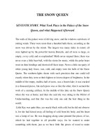
Figure 6-2. A mapping in which virtual addresses 4096 to
8191 are mapped onto main memory addresses 0 to 4095.
(a) (b)
Page Virtual addresses
15
14
13
12
11
10
9
8
7
6
5
4
3
2
1
0
61440 – 65535
57344 – 61439
53248 – 57343
49152 – 53247
45056 – 49151
40960 – 45055
36864 – 40959
32768 – 36863
28672 – 32767
24576 – 28671
20480 – 24575
16384 – 20479
12288 – 16383
8192 – 12287
4096 – 8191
0 – 4095
7
6
5
4
3
2
1
0
Page
frame
Bottom 32K of
main memory
Physical addresses
28672 – 32767
24576 – 28671
20480 – 24575
16384 – 20479
12288 – 16383
8192 – 12287
4096 – 8191
0 – 4095
Figure 6-3. (a) The first 64K of virtual address space divided
into 16 pages, with each page being 4K. (b) A 32K main
memory divided up into eight page frames of 4K each.
Present/absent
bit
Virtual
page
Page
table
15-bit
1
Memory address
Output
register
1 110
15
14
13
12
11
10
9
8
7
6
5
4
3
2
1
0
1 0 0 0 0 0 0 0 0 1 0 1 1 0
0 0 0 0 0 0 0 0 0 0 0 0 0 0 0 0 0 0 1 1 0 0 0 0 0 0 0 1 0 1 1 0
Input
register
20-bit virtual page 12-bit offset
32-bit virtual address
Figure 6-4. Formation of a main memory address from a virtual address.
Page table
Page
frame
0
1
0
0
1
0
0
1
0
1
1
0
1
0
1
1
0
4
0
0
5
0
0
3
0
7
6
0
2
0
0
1
Main memory
Page
frame
1 = Present in main memory
0 = Absent from main memory
7
6
5
4
3
2
1
0
Virtual page 6
Virtual page 5
Virtual page 11
Virtual page 14
Virtual page 8
Virtual page 3
Virtual page 0
Virtual page 1
Virtual
page
15
14
13
12
11
10
9
8
7
6
5
4
3
2
1
0
Figure 6-5. A possible mapping of the first 16 virtual pages
onto a main memory with eight page frames.
(a)
Virtual page 7
Virtual page 6
Virtual page 5
Virtual page 4
Virtual page 3
Virtual page 2
Virtual page 1
Virtual page 0
(b)
Virtual page 7
Virtual page 6
Virtual page 5
Virtual page 4
Virtual page 3
Virtual page 2
Virtual page 1
Virtual page 8
(c)
Virtual page 7
Virtual page 6
Virtual page 5
Virtual page 4
Virtual page 3
Virtual page 2
Virtual page 0
Virtual page 8
Figure 6-6. Failure of the LRU algorithm.
Virtual address space
Currently used
Call
stack
Constant
table
Symbol
table
Address space
allocated to the
call stack
Parse
tree
Source
text
Free
Figure 6-7. In a one-dimensional address space with growing
tables, one table may bump into another.
Segment
0
Symbol
table
Constant
table
Call
stack
Parse
tree
20K
16K
12K
8K
4K
0
Segment
1
Source
text
Segment
2
Segment
3
Segment
4
Figure 6-8. A segmented memory allows each table to grow or
shrink independently of the other tables.
Consideration Paging Segmentation
Need the programmer be aware of it? No Yes
How many linear addresses spaces are there? 1 Many
Can virtual address space exceed memory size? Yes Yes
Can variable-sized tables be handled easily? No Yes
Why was the technique invented? To simulate large
memories
To provide multiple
address spaces
Figure 6-9. Comparison of paging and segmentation.
,,
,
,
,
,,
Segment 1
(8K)
(a)
Segment 3
(8K)
Segment 3
(8K)
Segment 4
(7K)
Segment 4
(7K)
Segment 3
(8K)
Segment 2
(5K)
Segment 0
(4K)
(b)
Segment 7
(5K)
Segment 0
(4K)
(c) (d) (e)
Segment 2
(5K)
Segment 7
(5K)
Segment 0
(4K)
Segment 2
(5K)
Segment 5
(4K)
Segment 7
(5K)
Segment 0
(4K)
Segment 2
(5K)
Segment 6
(4K)
Segment 5
(4K)
Segment 7
(5K)
Segment 0
(4K)
Segment 6
(4K)
Segment 5
(4K)
Segment 2
(5K)
10K
(4K)
(3K)
(3K)
(3K) (3K)
(3K)
Figure 6-10. (a)-(d) Development of external fragmentation
(e) Removal of the external fragmentation by compaction.
18-Bit Segment
number
Segment
number
Descriptor
Descriptor
segment
Page
number
Page frame
Page
table
Offset
Word
Page
6-Bit page
number
10-Bit offset
within the page
Two-part MULTICS address
Figure 6-11. Conversion of a two-part
MULTICS
address into
a main memory address.
Bits 13 1 2
INDEX
0 = GDT
1 = LDT
Privilege level (0-3)
Figure 6-12. A Pentium II selector.
Relative
address
0
4
BASE 0-15 LIMIT
BASE 24-31 G D 0 LIMIT 16-19 P DPL TYPE BASE 16-23
0 : LIMIT is in bytes
1 : LIMIT is in pages
0 : 16-bit segment
1 : 32-bit segment
Segment type and protection
Privilege level (0-3)
0 : Segment is absent from memory
1 : Segment is present from memory
32 Bits
Figure 6-13. A Pentium II code segment descriptor. Data seg-
ments differ slightly.
Selector
Descriptor
Base address
Limit
Other fields
32-bit linear address
Offset
+
Figure 6-14. Conversion of a (selector, offset) pair to a linear address.
Bits
10 10 12
Linear address
DIR PAGE OFF
Page directory Page table Page frame
Word selected
(b)
(a)
DIR
PAGE
OFF
Figure 6-15. Mapping of a linear address onto a physical address.
Kernel
0
1
2
3
Level
Possible uses of
the levels
S
y
s
t
e
m
c
a
l
l
s
S
h
a
r
e
d
l
i
b
r
a
r
i
e
s
U
s
e
r
p
r
o
g
r
a
m
s
Figure 6-16. Protection on the Pentium II.
45 19
512K Virtual
page number
Offset
22 19
512K Page
frame
Offset
48 16
64K Virtual
page number
Offset
25
64K Page
frame
16
Offset
Bits
Virtual
address
51 13
8K Virtual
page number
Offset
Bits
Physical
address
28
8K Page
frame
13
Offset
42 22
4M Virtual
page number
Offset
22
Offset
19
4M Page
frame
Figure 6-17. Virtual to physical mappings on the UltraSPARC.