Tài liệu Crankshaft Optimization Using Behavior Modeling Pro/ENGINEER Wildfire 2.0 pptx
Bạn đang xem bản rút gọn của tài liệu. Xem và tải ngay bản đầy đủ của tài liệu tại đây (1.09 MB, 27 trang )
1
ME-430 INTRODUCTION TO COMPUTER AIDED DESIGN
Crankshaft Optimization Using Behavior Modeling
Pro/ENGINEER Wildfire 2.0
Dr. Herli Surjanhata
The engine designer has a requirement to keep the crank in balance and an objective
of reducing the crank mass to enable quicker engine startup.
Four basic studies will be performed on the crankshaft model:
• Analysis Features
• Sensitivity Study
• Feasibility Study
• Optimization Study
Sensitivity Analysis
Sensitivity analysis allows you to analyze how various measured quantities
(parameters) vary when a model dimension or an independent model parameter is
varied within a specified range. The result is a graph for each selected parameter
showing the value of the parameter as a function of the dimension.
This provides for understanding exactly how geometric changes to your model will
affect your engineering goals or specifications.
Feasibility and Optimization Studies
Feasibility and optimization studies allow you to have the system compute dimension
values that cause the model to satisfy certain user-specified constraints.
In a feasibility study, you define the following:
• A set of model dimensions to vary.
• A range within which each dimension can vary.
• A set of constraints that you want the design to satisfy.
The analysis constraints are defined as equalities or inequalities that use parameters
(which are the result of an analysis feature) and constant values. A sample
constraint may appear as follows: length < 6.3 or distance = 11.
To perform a feasibility study, the system does the following:
2
• The system attempts to find a set of dimension values within the specified
ranges that satisfies all of the constraints.
• If a solution is found, the model display changes to show these dimensions
modified to the new values.
You can either accept these new dimensions or undo the changes. The model can be
reverted to its state before the feasibility study. There can be many solutions in a
feasibility study that satisfy all constraint. The system converges to one of the
solutions.
With an optimization study, you can specify the goal function in addition to the
parameters for a feasibility study.
In an optimization study, you define the following:
• A set of dimensions to vary
• A range within which each dimension can vary
• A set of constraints that you want the design to satisfy
• A goal function to be optimized (maximized or minimized)–a goal function is
created as the result of an analysis feature
To perform an optimization study, the system does the following:
• The system looks for feasible solutions.
• Out of feasible solutions, the system selects the solution that optimizes the
goal function
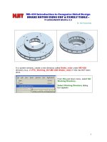
The crankshaft has the following dimensions:
3
Step 1:
Create a 1.25 in diameter cylinder using FRONT datum plane as sketching plane. The
extrusion depth is 0.5 in. Note that the center of the cylinder is 1.75 in. above TOP
datum plane.
Step 2:
Create an extrusion for the balancing body of the crankshaft. The dimensions of the
section to be extruded are shown below. The extrusion depth is 0.5 in.
4
Step 3:
Create another cylindrical extrusion with 1.5 in diameter and 2.0 in. length.
Step 4:
Mirror the geometry.
MATERIAL DENSITY
Under Edit pull down menu, select
Setup -> Mass Props
Enter density of steel as material of
crankshaft.
OK
Done.
5
ANALYSIS FEATURES
Click the Insert an analysis feature
icon
.
The ANALYSIS dialog box appears.
Change the Name to be CG, and hit
Enter.
Choose Model Analysis.
Hit Next button to continue.
6
Click the Compute button.
Then choose Close.
7
Parameters can be created for all the
results of the analysis. The can be used
later in relations, in notes in drawing, or to
drive optimizations.
In this case, create a parameter for volume
(by default).
Then click the Next button.
8
Features can be created at the center of
gravity (COG).
In this case create a point at the center of
gravity.
Select PNT_COG_.. (e.g. PNT_COG_282)
Choose YES under Create.
Click the Check
button to finish.
The analysis feature CG is now in the model
tree.
9
A view of the model from the
FRONT shows that Point located
at CG is not located at the axis
of revolution.
These must be brought
together to meet the design
goal.
Analyze the distance between the axis and point of CG.
AXIS OF
REVOLUTION
Datum point
at CG
10
Click the Insert an analysis feature
icon
.
The ANALYSIS dialog box appears.
Change the Name to be OFFSET, and
hit Enter.
Make sure the Type of analysis is
Measure.
Hit Next button to continue.