Tài liệu Configuring Frame Mode MPLS doc
Bạn đang xem bản rút gọn của tài liệu. Xem và tải ngay bản đầy đủ của tài liệu tại đây (180.83 KB, 12 trang )
1 - 12 CCNP: Implementing Secure Converged Wide-area Networks v5.0 - Lab 4-1 Copyright © 2007, Cisco Systems, Inc
Lab 4.1 Configuring Frame Mode MPLS
Learning Objectives
• Configure EIGRP on a router
• Configure Label Distribution Protocol on a router
• Change the size of the Maximum Transmission Unit (MTU)
• Verify MPLS behavior
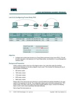
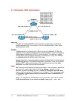
Topology Diagram
Scenario
In this lab, you will configure a simple Enhanced Interior Gateway Routing
Protocol (EIGRP) network to route IP packets. You will run Multiprotocol Label
Switching (MPLS) over the IP internetwork to fast-switch Layer 2 frames.
Step 1: Configure Addressing
Configure the loopback interfaces with the addresses shown in the topology
diagram. Also configure the serial interfaces shown in the diagram. Set the
clock rate on the appropriate interface and issue the
no shutdown command
on all serial connections. Verify that you have connectivity across the local
subnet using the
ping command.
R1(config)# interface loopback 0
R1(config-if)# ip address 172.16.1.1 255.255.255.0
R1(config-if)# interface fastethernet 0/0
R1(config-if)# ip address 172.16.12.1 255.255.255.0
R1(config-if)# no shutdown
R2(config)# interface loopback 0
R2(config-if)# ip address 172.16.2.1 255.255.255.0
R2(config-if)# interface fastethernet 0/0
R2(config-if)# ip address 172.16.12.2 255.255.255.0
R2(config-if)# no shutdown
R2(config-if)# interface serial 0/0/1
R2(config-if)# ip address 172.16.23.2 255.255.255.0
R2(config-if)# clockrate 64000
R2(config-if)# no shutdown
R3(config)# interface loopback 0
R3(config-if)# ip address 172.16.3.1 255.255.255.0
R3(config-if)# interface serial 0/0/1
R3(config-if)# ip address 172.16.23.3 255.255.255.0
R3(config-if)# no shutdown
Step 2: Configure EIGRP AS 1
Configure EIGRP for AS1 on all three routers. Add the whole major network
172.16.0.0 and disable automatic summarization.
R1(config)# router eigrp 1
R1(config-router)# no auto-summary
R1(config-router)# network 172.16.0.0
R2(config)# router eigrp 1
R2(config-router)# no auto-summary
R2(config-router)# network 172.16.0.0
R3(config)# router eigrp 1
R3(config-router)# no auto-summary
R3(config-router)# network 172.16.0.0
EIGRP neighbor adjacencies should form between R1 and R2 and between R2
and R3. If the adjacencies do not form, troubleshoot by checking your interface
configuration, EIGRP configuration, and physical connectivity.
What impact does IP connectivity have on MPLS?
Step 3: Observe CEF Operation
Since all the routers have EIGRP adjacencies and are advertising the entire
major 172.16.0.0 network, all routers should have full routing tables.
2 - 12 CCNP: Implementing Secure Converged Wide-area Networks v5.0 - Lab 4-1 Copyright © 2007, Cisco Systems, Inc
R1# show ip route
Codes: C - connected, S - static, R - RIP, M - mobile, B - BGP
D - EIGRP, EX - EIGRP external, O - OSPF, IA - OSPF inter area
N1 - OSPF NSSA external type 1, N2 - OSPF NSSA external type 2
E1 - OSPF external type 1, E2 - OSPF external type 2
i - IS-IS, su - IS-IS summary, L1 - IS-IS level-1, L2 - IS-IS level-2
ia - IS-IS inter area, * - candidate default, U - per-user static route
o - ODR, P - periodic downloaded static route
Gateway of last resort is not set
172.16.0.0/24 is subnetted, 5 subnets
D 172.16.23.0 [90/2172416] via 172.16.12.2, 00:01:56, FastEthernet0/0
C 172.16.12.0 is directly connected, FastEthernet0/0
C 172.16.1.0 is directly connected, Loopback0
D 172.16.2.0 [90/156160] via 172.16.12.2, 00:01:56, FastEthernet0/0
D 172.16.3.0 [90/2300416] via 172.16.12.2, 00:01:51, FastEthernet0/0
On R1, if you perform a traceroute to the R3s loopback, you see the path the
packet follows. This output changes slightly once we configure MPLS.
R1# traceroute 172.16.3.1
Type escape sequence to abort.
Tracing the route to 172.16.3.1
1 172.16.12.2 0 msec 0 msec 0 msec
2 172.16.23.3 16 msec 12 msec *
Cisco Express Forwarding (CEF) is Cisco’s proprietary Layer 3 switching
algorithm for Cisco IOS routers. CEF allows forwarding to be distributed
throughout the line cards on Cisco models like the Catalyst 6500. CEF also
provides quicker switching than switching based on the routing table (process
switching) or switching based on a standards-compliant forwarding information
base (fast switching).
What is the function of CEF?
Which information does CEF view as significant in making a forwarding
determination for an IP packet?
You can also see that CEF is enabled by default by using the
show ip cef
command
.
3 - 12 CCNP: Implementing Secure Converged Wide-area Networks v5.0 - Lab 4-1 Copyright © 2007, Cisco Systems, Inc
R1# show ip cef
Prefix Next Hop Interface
0.0.0.0/0 drop Null0 (default route handler entry)
0.0.0.0/32 receive
172.16.1.0/24 attached Loopback0
172.16.1.0/32 receive
172.16.1.1/32 receive
172.16.1.255/32 receive
172.16.2.0/24 172.16.12.2 FastEthernet0/0
172.16.3.0/24 172.16.12.2 FastEthernet0/0
172.16.12.0/24 attached FastEthernet0/0
172.16.12.0/32 receive
172.16.12.1/32 receive
172.16.12.2/32 172.16.12.2 FastEthernet0/0
172.16.12.255/32 receive
172.16.23.0/24 172.16.12.2 FastEthernet0/0
224.0.0.0/4 drop
224.0.0.0/24 receive
255.255.255.255/32 receive
Another important CEF command is the show ip cef non-recursive command
which allows the user to display CEF forwarding information for prefixes
installed in the routing table.
R1# show ip cef non-recursive
Prefix Next Hop Interface
172.16.1.0/24 attached Loopback0
172.16.2.0/24 172.16.12.2 FastEthernet0/0
172.16.3.0/24 172.16.12.2 FastEthernet0/0
172.16.12.0/24 attached FastEthernet0/0
172.16.12.2/32 172.16.12.2 FastEthernet0/0
172.16.23.0/24 172.16.12.2 FastEthernet0/0
CEF records both the Layer 3 next-hop information and the Layer 2 frame next-
hop information. CEF currently supports the following Layer 2 protocols: ATM,
Frame Relay, Ethernet, Fiber Distributed Data Interface (FDDI), PPP, High-
Level Datalink Control (HDLC), and tunnels.
CEF is critical to the operation of MPLS on Cisco routers because MPLS
packets must be forwarded based on label. Since the CEF architecture can
support multiple protocols such as IPv4, IPv6, CEF switching could naturally be
extended to support MPLS labels as well.
CEF should be enabled by default. If CEF is not enabled, issue the
ip cef
command in global configuration mode on each router.
Step 4: Enable MPLS on All Physical Interfaces
MPLS is a standardized protocol that allows routers to switch packets based on
labels, rather than route switch packets based on standards in the protocol’s
routing formula. Under normal IP routing, every intermediate system looks up
the destination prefix of an IP packet in the Routing Information Base (RIB) of a
router or in the Forwarding Information Base (FIB) of a fast switch at every
Layer 3 node. Instead of switching that is based on prefix, the first router
running MPLS can encapsulate the IP packet in an MPLS frame and then
4 - 12 CCNP: Implementing Secure Converged Wide-area Networks v5.0 - Lab 4-1 Copyright © 2007, Cisco Systems, Inc
further encapsulate the packet in the Layer 2 frame before sending it across
one of many supported Layer 2 media. At the next MPLS-enabled Label Switch
Router (LSR), the MPLS frame is read and the IP packet is switched as an
MPLS frame from router to router with little rewrite at each node.
This allows routers to switch multiple protocols (hence the name) using the
same switching mechanism, as well as perform some other functionality not
available in traditional destination-based forwarding, including Layer 2 VPNs
(AToM), Layer 3 VPNs, and traffic engineering. MPLS runs between Layers 2
and 3 of the OSI model and, because of this, is sometimes said to run at Layer
2½. The MPLS header is 4 bytes long and includes a 20-bit label.
Configuring the interface-level command
mpls ip on an interface tells the router
to switch MPLS packets inbound and outbound on that interface as well as
attempt to bring up MPLS adjacencies with the Label Distribution Protocol
(LDP) out that egress interface. LDP facilitates communication between MPLS
peers by allowing them to inform each other of labels to assign packets to
particular destinations based on Layer 2, Layer 3, or other significant
information.
Configure MPLS on all physical interfaces in the topology.
NOTE: If you are running the 12.4 version of the IOS on your routers, then the
mpls ip command is what you will use in this lab. However, when Cisco first
developed packet-labeling technology, it was called tag switching. Therefore, if
you are running an older version of the IOS, then you may see one of two
different variations. The first variation is that your router will accept the mpls ip
command. However, the commands will be stored in IOS as tag-switching
commands. The second variation is that your router will not accept the mpls ip
command. In this event, the
mpls ip command may be entered as the tag-
switching ip
command. Try the newer commands first, beginning with the
mpls keyword.
R1(config)# interface fastethernet0/0
R1(config-if)# mpls ip
R2(config)# interface fastethernet0/0
R2(config-if)# mpls ip
*Jan 31 08:28:54.315: %LDP-5-NBRCHG: LDP Neighbor 172.16.1.1:0 (1) is UP
R2(config-if)# interface serial0/0/1
R2(config-if)# mpls ip
R3(config)# interface serial0/0/1
R3(config-if)# mpls ip
*Jan 31 08:32:11.571: %LDP-5-NBRCHG: LDP Neighbor 172.16.2.1:0 (1) is UP
Notice that as you configure MPLS on both ends of a connection, IOS logs a
messages to the console on both routers indicating that an LDP neighbor
adjacency has formed.
5 - 12 CCNP: Implementing Secure Converged Wide-area Networks v5.0 - Lab 4-1 Copyright © 2007, Cisco Systems, Inc