Tài liệu GSM, cdmaOne and 3G systems P3 doc
Bạn đang xem bản rút gọn của tài liệu. Xem và tải ngay bản đầy đủ của tài liệu tại đây (1.43 MB, 54 trang )
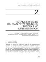
Chapter
3
Capacity of GSM Systems
3.1 List of Mathematical Symbols
a
i
represents path loss and shadow fading effects for the ith
MS
B TDMA carrier frequency
dA area occupied by an MS
da area occupied by an MS, or an area of ring centred around
a BS at a distance r
j
and having thickness dr
j
d
j
distance between an MS in jth cell and the zeroth BS
dφ infinitesimal change in φ
D distance between a cell site and the nearest co-channel cell
site
E
ϒ
j
]
average interference experienced at the zeroth BS due to all
MSs in the jth cell in the presence of frequency hopping
E
()]
expectation of
()
f
(
a
)
probability density function (PDF) of an MS’s location
area within a cell
f
i
ith carrier frequency
I
j
interference power from an MS in the jth cell at the zeroth
BS
I
0
j
I
j
in the presence of power control errors
I
T
total interference from J co-channel cells
J number of co-channel cells
k slot number in the TDMA frame
151
GSM, cdmaOne and 3G Systems. Raymond Steele, Chin-Chun Lee and Peter Gould
Copyright © 2001 John Wiley & Sons Ltd
Print ISBN 0-471-49185-3 Electronic ISBN 0-470-84167-2
152
CHAPTER 3. CAPACITY OF GSM SYSTEMS
M cluster size
N
f
number of carriers allocated to each BS
N
ts
time slots per carrier
P
j
(
r
j
)
transmitted power from the jth BS
P
T
MS transmit power
Q
(
k
)
Q-function
r distance between an MS and a BS in the same cell
R cell radius
S power received from an MS at a BS that is just sufficient to
maintain good communications
SIR signal-to-interference ratio
SIR
min
minimum SIR
S
0
received power at the BS in the presence of power control
errors
v
j
voice activity variables, 1 or 0
W width of the streets in street microcells
x normalised distance
(=
r
=
R
)
X distance from a microcell BS to the street microcell bound-
ary
X
b
path loss break-distance in street microcells
α path loss exponent (dB)
χ fraction of channels for signalling
δ random variable of the error in S
0
(dB)
δ
0
random variable of the power control error in the received
interference power
ε random variable with standard deviation
p
2 σ
e
λ shadow fading random variable for path r
λ
0
shadow fading random variable for path d
j
µ voice activity factor (VAF)
(=
E
v
j
])
φ angle between a line from an MS to its BS in the jth cell,
and a line between the zeroth and jthBSs(seeFigure3.3)
σ standard deviation of λ and λ
0
σ
ε
standard deviation of δ
ϒ
j
average interference power at the zeroth BS during slot-k,
frequency f
i
, from MSs over the jth cell in the presence of
frequency hopping
ϒ
0
j
ϒ
j
in the presence of power control errors
ζ rv
(
λ
0
λ
)
with standard deviation
p
2σ
3.2. INTRODUCTION
153
()
average of
()
3.2 Introduction
A precise analysis of the capacity of GSM is exceedingly complex, but by making reason-
able assumptions we can provide good estimates of the capacity for a variety of conditions.
We will confine ourselves to voice traffic channels since this represents the bulk of the traf-
fic in GSM networks [1–8]. While cognisant that radio cells are fundamentally irregular in
shape, depending on terrain, buildings, road topologies, and so forth, we will estimate the
capacity for hexagonal macrocells and for microcells in a rectilinear grid pattern of roads.
These types of cells have the virtue of simplicity and they enable the performance of other
systems to be compared on the same cellular basis.
The methodology used in the analysis of macrocellular GSM networks is as follows. We
will calculate the signal-to-interference ratios (SIRs) for different cluster sizes and identify
the cluster size (M) that will support the minimum acceptable SIR, namely SIR
min
. Knowing
M we will determine the number of channels per MHz per cell site, allowing for signalling
channels. The traffic carried by the network can then be computed for a given blocking
probability.
The SIR needs to be calculated for both up-link (reverse) and down-link (forward), and
for omnicells and sectorised cells. In computing the SIR we will make the following as-
sumptions: that the power control is applied; that frequency hopping (FH) is used where
the carrier in each frame hops beyond the coherence bandwidth; and that discontinuous
transmission (DTX) enables transmissions to be suspended on a link when the user is not
speaking [9–11]. All the traffic channels are considered to be occupied, and initially we will
ignore the signalling channels. The GSM radio link is assumed to be able to combat the ef-
fect of fast fading by means of its channel coding, bit interleaving, channel equalisation
and signal processing sub-systems. The radio channel is subjected to log-normal shadow
fading, and path losses that increase with distance raised to the power α.
Section 3.3 provides SIR calculations for transmissions in macrocellular GSM networks,
dealing with omnidirectional and sectorised cells, and examining the effect of power control
errors. The analysis is repeated in Section 3.4 for down-link transmissions. Armed with the
SIR calculations and the knowledge of cluster size M required to ensure SIR
min
, the capacity
of the hexagonal macrocellular network is determined in Section 3.5, along with the effect
of sectorisation on the teletraffic performance.
Section 3.6 is concerned with a street microcellular GSM network. The models used are
cross-shaped microcells formed by placing the base stations (BSs) at street intersections,
and rectangular-shaped microcells where the BSs are mid-way along the sides of the city
blocks. The cluster sizes for these two models are two and four, respectively. The other
154
CHAPTER 3. CAPACITY OF GSM SYSTEMS
parameters, e.g. DTX and FH, used in the macrocellular analysis apply. After calculating
the SIR the capacity of the microcellular GSM network is computed. Section 3.6 concludes
with a discussion of irregularly-shaped microcells.
3.3 Macrocellular GSM Network: Up-link Transmissions
3.3.1 The SIR for omnidirectional macrocells
We commence by determining the SIR for the up-link using omnidirectional antennas at the
cell sites [9]. Figure 3.1 shows the pattern of co-channel hexagonal cells in a macrocellular
network. The other cells are not shown, but we assume that there is a continuum of tes-
sellated hexagonal cells. Observe that around any cell there is an inner ring of co-channel
cells followed by outer rings of co-channel cells. Only the inner rings of co-channel cells
contribute significantly to the co-channel interference. Each ring has six co-channel cells,
except for a cluster size of two. This is because a hexagon has six sides. The distance be-
tween a cell site and the nearest cochannel cell site is D, and the distance between a cell site
and the apex of a hexagonal cell is R. A hexagonal cell may be approximated by a circle of
radius R as shown in Figure 3.2. Using this approximation we show in Figure 3.3 two cells,
the zeroth cell, and one of its co-channel cells, the jth cell.
We consider a mobile station (MS) in Figure 3.3 occupying an area da, at a distance r
from the jth BS. The MS transmits a power P
T
such that the received power at the jth BS is
S, a power just sufficient to maintain good communications. The received signal decreases
as the MS moves away from the cell site because of an increase in the path loss. The
received power at a distance r from the BS will be different at different angles because of
the variations in the terrain and the distribution of buildings and streets. We allow for these
variations by introducing a random variable λ having zero mean and standard deviation σ.
Often λ is referred to as a shadowing random variable because it is associated with the
electromagnetic shadows cast by buildings and terrain variations. The received power in
dBs is
10log
10
S
=
10log
10
P
T
α10 log
10
r
+
λ
(3.1)
where the path loss is α 10log
10
r ,andα is called the path loss exponent. Note that λ is in
dBs. Measurements of λ show that it is normally distributed between
4σ and 2σ [2]. Since
λ is in dBs, it is said to be log-normally distributed between
4α and 2σ.Inordertomake
S a constant, P
T
is varied using a closed-loop power control system. From Equation (3.1)
the power transmitted by the MS is
P
T
=
Sr
α
10
λ
=
10
(3.2)
and this power causes interference at the zeroth BS. The actual interference depends on the
3.3. MACROCELLULAR GSM NETWORK: UP-LINK TRANSMISSIONS
155
D
R
D
Figure 3.1: Co-channel cells in a mosaic of tessellated hexagonal cells. Non-co-channel cells are
not displayed.
R
Figure 3.2: An hexagonal cell and its circular representation.
r
D
d
j
0-th cell
j-th cell
φ
da
dφ
dr
BS
j
MS
R
Figure 3.3: Up-link: an MS in the jth cell interfering with the zeroth BS.
156
CHAPTER 3. CAPACITY OF GSM SYSTEMS
distance d
j
between the MS and the zeroth BS, namely
d
j
=
q
D
2
j
+
r
2
2D
j
r cos φ
(3.3)
where D
j
and φ are shown in Figure 3.3. The interference also depends on the shadow
fading affecting the MS’s transmissions over the path between it and the zeroth BS. The
interference due to the MS in the jth cell at the zeroth cell site is
I
j
=
P
T
d
α
j
10
λ
0
=
10
(3.4)
where λ
0
is the shadowing variable for path d
j
. Observe that the shadowing variables λ
and λ
0
have the same variance σ
2
,andthatα is assumed to be universal over the entire
geographical area. Substituting P
T
from Equation (3.2) into Equation (3.4) yields
I
j
=
S
r
d
j
α
10
(
λ
0
λ
)=
10
(3.5)
and
ζ
=
λ
0
λ (3.6)
is a random variable having a normal distribution with standard deviation
p
2σ, with
4
p
2σ
<
ζ
<
2
p
2σ
(3.7)
Unlike the digital enhanced cordless telecommunication (DECT) system [12], GSM cannot
hop onto a different radio carrier at each time slot. The radio carrier only hops to a new
frequency every GSM frame. In first generation GSM equipment the carriers are assigned
to a cell site (or sector) and hopping only occurs between these carriers. This is termed
baseband frequency hopping. Second generation equipment facilitates hopping over all
GSM frequencies and this is termed RF frequency hopping. We will consider the special
case of the beacon carrier at a later stage.
Let each BS be allocated N
f
carriers, say f
1
, f
2
, f
3
:::
f
Nf
, and each carrier supports N
ts
time slots, resulting in N
ts
N
f
traffic channels per cell. The carriers are hopped on a frame-
by-frame basis. Each user is assigned a specific slot in a time frame and it stays in this slot
as frequency hopping occurs and the call progresses. Consider the kth timeslot supported
by carrier frequency, f
i
.Inthejth interfering cell, although all the users change their carrier
frequency during each TDMA frame, there is always a user who occupies the kth timeslot of
the carrier f
i
. Owing to frequency hopping at each TDMA frame the interference associated
with the channel specified by the kth timeslot and f
i
carrier can come from users in different
locations within the jth cell, although the interference is only from one user during any
frame. Eventually frequency f
i
will be used by a subset of N
f
users who occupied the kth
timeslot in the jth cell. If there is a sufficiently large number of carriers, and the MSs are
3.3. MACROCELLULAR GSM NETWORK: UP-LINK TRANSMISSIONS
157
uniformly distributed over the jth cell, then the probability that an MS will be using the
kth slot on carrier f
i
is f
(
a
)
da ,where f
(
a
)
is the probability density function (PDF). This
probability is also da
=(
πR
2
)
,giving
f
(
a
)=
1
πR
2
:
(3.8)
The average interference power at the zeroth BS during the kth slot on frequency f
i
is
ϒ
j
=
Z
cell
Z
area
I
j
f
(
a
)
da
(3.9)
where I
j
is the interference from location da. Substituting I
j
from Equation (3.5) into Equa-
tion (3.9), and using Equation (3.6) yields
ϒ
j
=
S
πR
2
Z
R
0
Z
2π
0
r
d
j
α
10
ζ
=
10
r dr dφ (3.10)
where da has been replaced by r dr dφ,anddr and dφ are defined in Figure 3.3. The variable
ζ depends on the paths between the MS and the jth and zeroth BSs while communicating
using the kth slot on carrier f
i
. Owing to hopping, the MS using the kth slot on carrier f
i
is located in a different part of the jth cell during each TDMA frame and thereby has a
different shadow variable ζ. Consequently we must take the expectation or average of ϒ
j
to
get the average of 10
ζ
=
10
and hence obtain the total interference experienced at the zeroth
cell site due to all the mobiles in the jth cell, namely
E
ϒ
j
]=
S
πR
2
Z
R
0
Z
2π
0
r
d
j
α
E
10
ζ
=
10
]
r dr dφ
(3.11)
where E
()]
means the expectation of
()
. Normalising the distance as
x
=
r
=
R
0
x
1
E
ϒ
j
]
S
=
1
π
Z
1
0
Z
2π
0
x
d
j
=
R
α
E
h
10
ζ
=
10
i
x dx dφ
:
(3.12)
We now need to determine E
h
10
ζ
=
10
i
.
3.3.1.1 Expectation of E
h
10
ζ
=
10
i
We have stated that the shadow random variable λ is a normal random variable, but bounded
from
4σ to
+
2σ. These limits have been experimentally observed [2]. Since ζ is the
difference between two independent random variables λ, ζ is bounded as given by Inequality
158
CHAPTER 3. CAPACITY OF GSM SYSTEMS
(3.7). Let us commence to find E
10
ζ
=
10
]
on the basis that ζ is from
∞ to
+
∞ ,andthen
examine the case when
4
p
2σ
<
ζ
<
2
p
2σ .
Because ζ is a normal random variable,
E
10
ζ
=
10
]=
Z
∞
∞
10
ζ
=
10
exp
ζ
2
4σ
2
(
4πσ
2
)
1
=
2
dζ
:
(3.13)
Setting
10
ζ
=
10
=
exp
(
z
)
or
z
=
ζ
10
ln
(
10
)
then
E
h
10
ζ
=
10
i
=
Z
∞
∞
exp
ζ
10
ln
(
10
)
1
2
ζ
2
2σ
2
(
4πσ
2
)
1
=
2
dζ
=
Z
∞
∞
exp
σ
ln
(
10
)
10
2
1
2
ζ
p
2σ
p
2σ
ln
(
10
)
10
2
(
4πσ
2
)
1
=
2
dζ
=
exp
σ ln
(
10
)
10
2
Z
∞
∞
exp
1
2
ζ
p
2σ
p
2σ
ln
(
10
)
10
2
(
4πσ
2
)
1
=
2
dζ
and the integral is unity because it represents a normal distribution of mean
p
2σln
(
10
)=
10.
The expectation is, therefore,
E
10
ζ
=
10
]=
exp
σ ln
(
10
)
10
2
(3.14)
If we truncate the normal distribution of ζ at
4
p
2σ and 2
p
2σ, then we rewrite Equa-
tion (3.13) as
E
10
ζ
=
10
]=
1
Q
(
4
)
Q
(
2
)
Z
2
p
2σ
4
p
2σ
10
ζ
=
10
:
exp
ζ
2
4σ
2
(
4πσ
2
)
1
=
2
dζ
(3.15)
where
Q
(
k
) =
1
p
2π
Z
∞
k
exp
(
λ
2
=
2
)
dλ
E
10
ζ
=
10
] =
1
:
023exp
σ ln
(
10
)
10
2
Z
2
p
2σ
4
p
2σ
exp
1
2
n
ζ
p
2σ
p
2σ
ln
(
10
)
10
o
2
(
4πσ
2
)
1
=
2
dζ
:
(3.16)
3.3. MACROCELLULAR GSM NETWORK: UP-LINK TRANSMISSIONS
159
Let
x
=
ζ
p
2σ
p
2σ ln
(
10
)
10
(3.17)
then
dx
=
dζ
p
2σ
; (3.18)
E
10
ζ
=
10
] =
1
:
023 exp
σ ln
(
10
)
10
2
p
2σ
(
4πσ
2
)
1
=
2
Z
2
p
2σ ln
(
10
)
10
4
p
2σ ln
(
10
)
10
exp
x
2
2
dx
=
1
:
023 exp
σ ln
(
10
)
10
2
"
Q
(
4
p
2σ ln
(
10
)
10
)
Q
(
2
p
2σ ln
(
10
)
10
)#
:
(3.19)
3.3.1.2 Discontinuous transmission (DTX)
A voice activity detection (VAD) circuit is used to detect when a user is speaking. When
a user is silent, the transmissions to and from this user are essentially stopped, although
background noise at a low bit rate is sent, as described in Section 2.8.1. The VAD therefore
supports discontinuous transmissions (DTX), i.e. transmissions that only occur when a user
is speaking. To allow for DTX we introduce a voice activity variable
v
j
=
(
1
with probability µ
0
with probability 1
µ
(3.20)
and µ is called the voice activity factor (VAF). The mean of v
j
is
E
v
j
]=
µ
:
(3.21)
When we include DTX, the total interference from the MSs in the jth cell is decreased to
E
v
j
]
E
ϒ
j
]
. Extending the situation to include J co-channel cells, we have a total interfer-
ence of
I
T
=
J
∑
j
=
1
E
v
j
]
E
ϒ
j
]
(3.22)
and with the aid of Equation (3.21) we have
SIR
=
S
µ
∑
J
j
=
1
E
ϒ
j
]
(3.23)
and normally J is set to six.
160
CHAPTER 3. CAPACITY OF GSM SYSTEMS
3.3.1.3 Computing the SIR
We need to compute the graph of SIR as a function of cluster size M (or reuse factor), and
then note the minimum value of M that provides an SIR above SIR
min
. By using this value
of M the radio links will operate with an acceptable bit error rate (BER). Figures 3.4 and
3.5 show examples of tessellated cells in three and seven cell clusters. The first step is to
note that the distance between co-channel cell sites, D,isgivenby
D
=
R
p
3M
(3.24)
where R is the cell radius and M is the cluster size. The path loss exponent α is set to
4 (although others might prefer 3.5). The standard deviation σ of the shadow fading is 8
dB, and E
10
ζ
=
10
]
is calculated using Equation (3.19). Three values of the VAF, i.e. µ,are
used: 1.0, when all users are speaking, which is a worse case scenario, and 1/2 and 3/8.
In normal conversation a speaker on average may speak for only 40% or so of the time.
We observe that in any one slot there are only six significant interferers in a fully loaded
system, i.e. the received packet in the kth slot on carrier f
i
has interference from six other
MSs. We will assume that the BSs have sufficient carriers to ensure that DTX has statistical
meaning. Using the above parameters and on computing by numerical methods, the SIR
of Equation (3.23) is calculated for different values of cluster size M. The variation in SIR
as a function of M is displayed in Figure 3.6. Note the low gradient of the curves. This is
unfortunate as we would prefer the SIR to increase rapidly with cluster size, producing a
substantial increase in SIR for a small increase in M. Instead, considerable increases in M
yield a relatively small increase in SIR. This feature is common to both frequency division
multiple access (FDMA) and time division multiple access (TDMA) systems using fixed
channel allocation (FCA) techniques. The SIR
min
for GSM is said to be 9 dB [2], although
operators employ a higher figure, sometimes 12 dB or more. Using the best figure of 9 dB,
Figure 3.6 shows that for a VAF of 3/8 a three-cell cluster could be used, but if a conservative
design is done and VAF is ignored, i.e. VAF = 1, then the minimum cluster size is five for
up-link transmissions.
3.3.2 The SIR for sectorised macrocells
Sectorisation of cells is generally employed in current macrocellular systems. This is be-
cause macrocellular cell sites are often on the tops of tall buildings and as the terrain may
vary in different directions, and because of the high rents for these sites, it is common to
employ directional antennas with each antenna covering a particular sector. Although six
and four sectors are used, the most common is the three-sector cell.
We will now consider sectorising our cells. Ideal sectorisation will be assumed. This
means that the radiation pattern will be precisely the area of a sector with no backlobes.
3.3. MACROCELLULAR GSM NETWORK: UP-LINK TRANSMISSIONS
161
Figure 3.4: Up-link: three cells per cluster, omnidirectional sites. Co-channel cells are shown
shaded.
Figure 3.5: Tessellated clusters with seven cells per cluster, omnidirectional sites.
162
CHAPTER 3. CAPACITY OF GSM SYSTEMS
Figure 3.6: Up-link SIR versus number of cells per cluster.
The SIR will be calculated for different cluster sizes where each cell has three sectors. This
will eventually lead to us understand how sectorisation affects the traffic carried by the
network.
3.3.2.1 Sectorisation for three- and four-cell clusters
Figure 3.7 shows a three-cell cluster with three sectors per cell, while Figure 3.8 displays
a four-cell cluster with three sectors per cell. Note that sectorisation produces sectors that
are essentially smaller cells, and that the spectrum at each site has been partitioned into
three parts. The most apparent effect of sectorisation is to decrease the number of first tier
co-channel cells from six to just two sectors. For the sectorised situation, Equation (3.12)
becomes
E
ϒ
j
]
S
=
3
π
Z
1
0
Z
2π
=
3
0
x
d
j
=
R
α
E
10
ζ
=
10
]
x dx dφ (3.25)
as φ is from 0 to 2π
=
3and f
(
a
)=
3
=
πR
2
. This equation is the interference-to-signal ratio
(ISR) for the total interference in the zeroth sector from the jth sector. Since there are two
significant interfering sectors, and allowing for DTX, the SIR for the three cell clusters with
three sectors per cell is
SIR
=
S
2µE
ϒ
j
]
:
(3.26)
Employing Equation (3.19), the SIR for the four cell clusters is 17.8, 20.8 and 22 dB for
µ
=
1
1
=
2and3
=
8, respectively. The corresponding SIRs for the three-cell clusters are
3.3. MACROCELLULAR GSM NETWORK: UP-LINK TRANSMISSIONS
163
14.9, 17.9 and 19.1 dB, respectively. The improvement in SIR due to sectorisation is 9.5 dB
as a result of the lower E
ϒ
j
]
.
3.3.2.2 Sectorisation for the two-cell cluster
Figure 3.9 shows tessellated two-cell clusters where each cell has three sectors. This cellular
topology yields asymmetrical interference conditions. In sectors 1 and 2 there are four co-
channel interfering sectors on the central cell site, where two of the co-channel cells are at
a distance D
j
of 2
p
3R, one is 3R and the closest is at
p
3R. Sector 3 has five interfering
sectors on the central cell site. The closest is at 3R, while two are at 2
p
3R and the other
two at 4.72R. The values of D
j
for a particular sector are inserted into Equation (3.3) and
d
j
computed as a function of x
=
r
=
R and φ.NextE
ϒ
j
]
is found for this interfering sector
using Equation (3.25). The interference is computed for mobiles (which use omnidirectional
antennas) from each sector, and the SIR is computed using Equation (3.23), where J is either
4or5.
The computed SIR values for sectors 1 and 2 are 7.7, 10.7 and 11.9 dB for VAFs, i.e.
values of 1, 1/2, and 3/8, respectively. The SIR of sector 3 is higher because although there
are five co-channel sectors, they are all spaced by at least two cells. The corresponding
SIR values are 13.9, 16.9 and 17.9 dB. However, note that the interfering sectors 3 are in a
contiguous line, and mobiles near the corner of one sector are likely to interfere with mobiles
in an adjacent sector. Consequently, the SIR values for sectors 3 are somewhat optimistic.
Indeed, this contiguous group of five sectors 3 may invalidate the two-cell cluster option.
3.3.2.3 Sectorisation for the single-cell cluster
Since the spectral efficiency in fixed channel allocation networks is inversely proportional to
the cluster size, it follows that it would be highly desirable if the entire bandwidth allocation
could be deployed at every cell site. Let us determine if sectorisation will facilitate single-
cell frequency reuse by calculating the SIR. Figure 3.10 shows the cellular arrangement.
The reuse distances D
j
for sectors E and F are
p
3R . The next closest sectors are D, B and
GatD
j
=
3R, while the remaining sectors A and C are at 2
p
3R. The procedure outlined
in Section 3.3.2.2 is employed again, and we display our SIR values, along with the others
evaluated in Section 3.3.2, in Table 3.1. We also include the SIR values for a three-cell
cluster without sectorisation as a bench marker. Observe that as with the two-cell cluster,
the single-cell cluster has contiguous co-channel sectors. The interference between adjacent
sectors is likely to exceed the interference to the zeroth cell sector.
If the SIR for GSM is taken as 9 dB, then the three cells per cluster only works with
omnicells when VAF = 3/8. It is therefore better to use sectorisation when the SIR is 14.9
dB even when VAF = 1. Single-cell clusters will not work, but a cluster size of two with
164
CHAPTER 3. CAPACITY OF GSM SYSTEMS
D
j
d
j
j-th sector
φ
j
φ
interfering MS
0-th sector
Figure 3.7: Up-link: three-cell cluster with three sectors per cell. The two most significant interfer-
ing sectors are shown shaded.
D
j
d
j
j-th sector
φ
j
φ
interfering MS
0-th sector
Figure 3.8: Up-link: four-cell clusters with three sectors per cell. The two most significant interfer-
ing sectors are shown shaded.
3.3. MACROCELLULAR GSM NETWORK: UP-LINK TRANSMISSIONS
165
sector 1:
sector 3:
sector 2:
MS:
B
BS
MS
BS
BS
BS
C
A
Figure 3.9: Up-link: two-cell clusters with three sectors per cell.
d
j
D
j
MS:
BS
0-th cell
j-th cell
A
B
C
E
F
G
D
φ
j
φ
Figure 3.10: Up-link: single-cell cluster with three sectors per cell.
166
CHAPTER 3. CAPACITY OF GSM SYSTEMS
Table 3.1: Up-link: SIR values for different cluster sizes and sectorisation.
Cluster Number of Significant
size sectors VAF = 1 VAF = 1/2 VAF = 3/8 interferers
3 0 5.4 8.4 9.6 6
3 3 14.9 17.9 19.1 2
2 3 7.7 10.7 11.9 4
1 3 4.6 7.6 8.9 7
three ideal shaped sectors per cell will work for a VAF of about 1/2 or lower. Before we
discuss the ramifications of these cluster sizes and sectors on the teletraffic carried, we must
examine the SIR values on the down-link.
3.3.2.4Effect of imperfect power control in the SIR
Power control errors occur, especially in fast fading channels, and the received power is
S
0
=
S10
δ
10
(3.27)
rather than the target power, S, where 10
δ
10
is the power control error, and δ is a normally dis-
tributed random variable having a standard deviation of σ
e
[13]. Because of power control
errors the mobile transmitted power in Equation (3.2) becomes
P
T
=
S
0
r
α
10
λ
10
=
Sr
α
10
λ
10
10
δ
10
(3.28)
The interfering power at the zeroth cell BS from an MS in the jth cell is obtained from
Equation (3.5) as
I
0
j
=
S
0
r
d
j
α
10
ζ
10
=
S
r
d
j
α
10
ζ
10
10
δ
0
10
(3.29)
where δ
0
is the random variable of the interference power due to imperfect power control.
The average of the received power from mobiles located anywhere within the jth cell using
the kth timeslot can be found by inserting 10
δ
0
10
into Equation (3.10), namely
ϒ
0
j
=
S
πR
2
Z
R
0
Z
2π
0
r
d
j
α
10
ζ
10
10
δ
0
10
rdrdφ
(3.30)
From Equations (3.27) and (3.30), the interference-to-signal power ratio for imperfect power
controlled up-link is
ϒ
0
j
S
=
1
π
Z
1
0
Z
2π
0
x
d
j
=
R
α
10
ζ
10
10
ε
10
xdxdφ
(3.31)
3.4. MACROCELLULAR GSM NETWORK: DOWN-LINK TRANSMISSIONS
167
where ε is a random variable
ε
=
δ
0
δ (3.32)
having a normal distribution with a standard deviation of
p
2σ
e
.Sinceζ and ε are two
mutually independent random variables, the mean value of Equation (3.31) is
E
ϒ
0
j
S
0
=
E
h
10
ζ
10
i
E
h
10
ε
10
i
1
π
Z
1
0
Z
2π
0
x
d
j
=
R
α
xdxdφ
:
(3.33)
Compared with the interference-to-signal ratio for perfect power control given by Equa-
tion (3.12), there is an increase of E
h
10
ε
10
i
in the interference-to-signal ratio due to imper-
fect power control. The corresponding decrease in the SIR is0.2dB,0.9dB,and2.1dBfor
δ having a standard deviation of 1 dB, 2 dB and 3 dB, respectively, irrespective of the voice
activity factor and cluster size.
3.4Macrocellular GSM Network: Down-link Transmissions
3.4.1 The SIR for omnidirectional macrocells
The BSs in the tessellated hexagonal structures adjust the transmitted power to their mo-
biles such that each mobile receives a power S. This statement implies perfect power con-
trol. Again frequency hopping beyond the coherence bandwidth is assumed, and DTX is
applied. Mobiles receive interference from nearby BSs, and not from other mobiles. Thus,
as the MSs move around the cell the interference they experience varies, but the sources
of interference are static. The SIR on the down-link is dependent upon the location of an
MS, and this leads us to consider the average SIR for the mobiles in a cell, or the SIRsfor
particular mobiles.
Figure 3.11 shows an MS at a distance r from its BS in the zeroth cell. The MS occupies
an area dA. In the figure the source of interference is from the jth BS in the jth cell.
The distance between the two base sites is D
j
. Suppose that the MS receives information
fromitszerothBSinthek-slot on carrier f
i
. The interference is caused by the jth BS
when it transmits to an MS in its cell on the k-slot on carrier f
i
, and the magnitude of this
interference depends on where this MS is located. In Figure 3.11 we display a ring distance
r
j
from the jth cell site. The area of this ring is
da
=
π
(
r
j
+
dr
j
)
2
πr
2
j
2πr
j
dr
j
(3.34)
All MSs in this ring receive a power S, and this means that the jth BS transmitted power is
P
j
(
r
j
)=
Sr
α
j
10
λ
j
=
10
(3.35)
168
CHAPTER 3. CAPACITY OF GSM SYSTEMS
Figure 3.11: Down-link: two-cell cluster with three sectors per cell.
where α is the path loss exponent and λ
j
is the shadow fading random variable. For MSs
uniformly distributed over the jth cell, the average transmitted power per channel from the
jth BS is
P
j
(
r
j
)=
Z
cell
Z
area
P
j
(
r
j
)
f
(
a
)
da
(3.36)
where f
(
a
)
is given by Equation (3.8). Consequently,
P
j
(
r
j
) =
Z
R
0
Sr
α
j
10
λ
j
=
10
1
πR
2
2πr
j
dr
j
=
2
α
+
2
SR
α
10
λ
j
=
10
(3.37)
where R is the cell radius. This average transmitted power from the jth BS is the source of
interference to MSs in the zeroth cell. The particular MS at a distance d
j
from the jth BS
receives an interference power of
I
j
=
P
j
(
r
j
)
10
λ
0
=
10
d
α
j
(3.38)
where λ
0
is the shadowing random variable for path d
j
. Substituting P
j
(
r
j
)
from Equa-
tion (3.37) into Equation (3.38) yields
I
j
=
2
α
+
2
S 10
ζ
=
10
R
d
j
α
(3.39)
where
ζ
=
λ
0
λ
j
(3.40)
has a standard deviation of
p
2σ,andwhereσ is the standard deviation of λ
0
and λ
j
.The
distance d
j
is given by Equation (3.3).
3.4. MACROCELLULAR GSM NETWORK: DOWN-LINK TRANSMISSIONS
169
3.4.1.1 Average SIR
The N
f
carriers in the zeroth cell, associated with N
f
users assigned to the kth slot, are
uniformly distributed over the area of the cell. It is important to realise that for a uniform
distribution to have validity, N
f
must be sufficiently large. This in turn means that the op-
erator has a wide bandwidth at his disposal. We will now consider the average interference
experienced by mobiles in the zeroth cell from the jth BS. The area dA shown in Figure 3.11
is rdφdr,andthePDF f
(
A
)
is again 1
=
πR
2
, and hence the interference average over the ze-
roth cell is, with the aid of Equation (3.39),
ϒ
j
=
Z
2π
0
Z
R
0
2S
α
+
2
10
ζ
=
10
R
d
j
α
1
πR
2
rdφdr (3.41)
and on normalising r by introducing x
=
r
=
R,
ϒ
j
=
2S
(
α
+
2
)
π
Z
2π
0
Z
1
0
10
ζ
=
10
R
d
j
α
xdφdx
:
(3.42)
Note that
d
j
R
2
=
D
j
R
2
+
x
2
2
D
j
R
xcos φ
and that the number of cells per cluster from Equation (3.23) is
M
=
1
3
D
j
R
2
(3.43)
giving
d
j
R
2
=
3M
+
x
2
2
p
3Mxcos φ
:
(3.44)
Owing to frequency hopping, the expectation of
I
j
is made with respect to the random
variable ζ, because ζ is different for each hop. This expectation is
E
ϒ
j
=
2S
(
α
+
2
)
π
Z
2π
0
Z
1
0
E
h
10
ζ
10
i
R
d
j
α
xdφdx
(3.45)
where E
h
10
ζ
10
i
is given by Equation (3.19). The SIR can be found from Equations (3.23)
and (3.45), namely
S
I
=
S
∑
J
j
=
1
E
v
j
]
E
ϒ
j
=
1
2µ
(
α
+
2
)
π
∑
J
j
=
1
R
2π
0
R
1
0
E
h
10
ζ
10
i
R
d
j
α
xdφdx
(3.46)
170
CHAPTER 3. CAPACITY OF GSM SYSTEMS
For a hexagonal pattern of cells there are six close interferers, as shown in Figure 3.12. We
compute E
h
10
ζ
=
10
i
in Equation (3.19) for a path loss exponent of α
=
4, and for shadow
fading with a standard deviation of σ
=
8. This expectation value is inserted into Equation
(3.46) and the SIR found. When the number of cells per cluster M is changed, d
j
changes
(as evident in Equation (3.44)), which in turn changes the SIR. Graphs of the SIR as a
function of the number of cells per cluster are displayed in Figure 3.13 for three different
voice activity factors (VAFs) of 1, 1
=
2, and 3
=
8. For three cells per cluster, the average SIRs
forVAFsof1,1
=
2, 3
=
8are5
:
9dB,8
:
9dB,and10
:
1 dB, respectively. Compared with the
SIR on the up-link system, the average SIR on the down-link system is 0
:
5dBlarger.
3.4.1.2 The SIR of mobiles in different locations
We now examine the SIR of the three-cell cluster arrangement for MSs at different locations
within its cell, from the immediate vicinity of the BS
(
r
=
0
)
to the cell boundary, r
=
R.
As a consequence, those MSs near their BS will receive less interference power than MSs
at locations away from their BS. From Equations (3.23) and (3.39), the SIR is
S
I
=
1
∑
J
j
=
1
E
v
j
]
E
h
ϒ
j
S
i
=
1
2µ
α
+
2
∑
J
j
=
1
E
h
10
ζ
10
i
R
d
j
α
(3.47)
where E
h
10
ζ
10
i
is given by Equation (3.19). For three cells per cluster, the graphs of the
SIR for MSs along a line from the zeroth BS site to a corner of the zeroth cell, is shown in
Figure 3.14. The worst SIR occurs when mobiles are located at the corner
(
x
=
1
)
where the
SIRsare4
:
8dB,7
:
8dB,and9
:
2 dB for VAFs of 1, 1
=
2, and 3
=
8, respectively. The worst
case SIR is about 1 dB less than the average SIR, while the SIR difference between the best
and worst case is about 2 dB.
3.4.2 The SIR for sectorised macrocells
By dividing each cell into three sectors, as we did for the up-link in Section 3.3, we have
the arrangement shown in Figure 3.15. By averaging over the sector area, the average SIR
can be found from Equation (3.46), namely
S
I
=
S
∑
J
j
=
1
E
v
j
]
E
ϒ
j
=
1
6µ
(
α
+
2
)
π
∑
J
j
=
1
R
2π
3
0
R
1
0
E
h
10
ζ
10
i
R
d
j
α
xdφdx
(3.48)
From Equation (3.47), the SIR for mobiles at different locations is
S
I
=
S
∑
J
j
=
1
E
v
j
]
E
ϒ
j
=
1
2µ
α
+
2
∑
J
j
=
1
E
h
10
ζ
10
i
R
d
j
α
(3.49)
3.4. MACROCELLULAR GSM NETWORK: DOWN-LINK TRANSMISSIONS
171
Figure 3.12: Down-link: three-cell cluster, omnidirectional sites.
Figure 3.13: Down-link SIR as a function of cluster size for different VAFs. No sectorisation.
172
CHAPTER 3. CAPACITY OF GSM SYSTEMS
Figure 3.14: Down-link: the SIR for mobiles at normalised distance r
=
R from the BS, for different
VAFs. No sectorisation.
The average SIRs for VAFs of 1, 1
=
2, and 3
=
8are14
:
1dB,17
:
1dB,and18
:
4 dB, respec-
tively, for the three-cell cluster. The SIRs for mobiles located along the line AB in Figure
3.15 are shown in Figure 3.16. The SIRs for mobiles at location B (where r
=
R
=
0
:
87) are
15
:
7dB,18
:
7dB,and19
:
9 dB for VAF values of 1, 1
=
2, and 3
=
8, respectively. The worst
SIR conditions occur when the mobiles are located near the BS in Figure 3.15, where the
SIRsare11
:
7dB,14
:
7dB,and15
:
9dBforVAFof1,1
=
2, and 3
=
8, respectively. This is
because the power control means that the mobile still receives the same power S, in spite
of being near its BS, while the distance between the interfering BSs has decreased. The
difference between the two extreme cases of r
=
R of 0 and 0
:
87 is about 4 dB, which is 2 dB
larger than that for the unsectorised system.
3.4.2.1 The special case of a two-cell cluster
The down-link SIR of the two-cell cluster TDMA system with three sectors per cell is cal-
culated for the two different interference situations considered on the up-link. The average
SIR can be evaluated from Equation (3.48), but now the co-channel separation D
j
is dif-
ferent. From Figure 3.17, mobiles in sector 1 of the centre cell experience intercellular
interference from four BSs that are transmitting to mobiles in their sector 1. Mobiles in
sector 2 of the centre cell also have intercellular interference from four BSs, but mobiles in
sector 3 of the central cell are subjected to interference from BSs in five sectors positioned
along a line as shown in Figure 3.17. Following a similar procedure as used above, we find
that the average SIR for mobiles in sectors 1 and 2 are 7
:
7dB,10
:
7dB,and11
:
9dBfora
VA F o f 1 , 1
=
2, and 3
=
8, respectively, while for mobiles in sector 3 the average SIR values
3.4. MACROCELLULAR GSM NETWORK: DOWN-LINK TRANSMISSIONS
173
Figure 3.15: Down-link: three cells per cluster with three sectors per cell. Primary interfering sec-
tors are shown shaded.
Figure 3.16: Down-link SIR for mobiles as a function of normalised distance r
=
R from the BS to
the boundary along the line AB in Figure 3.15 for different VAFs; three sectors per cell
and three cells per cluster.
174
CHAPTER 3. CAPACITY OF GSM SYSTEMS
sector 1:
sector 3:
sector 2:
MS:
B
BS
MS
BS
BS
BS
C
A
Figure 3.17: Down-link: two-cell cluster with three sectors per cell.
Figure 3.18: Down-link: the SIR for mobiles as a function of normalised distance r
=
R along the
boundaries AB and AC for different VAFs; three sectors per cell and two cells per
cluster.
3.4. MACROCELLULAR GSM NETWORK: DOWN-LINK TRANSMISSIONS
175
are 13
:
9dB,16
:
9dB,and17
:
9 dB for a VAF of 1, 1
=
2, and 3
=
8, respectively.
The SIR for MSs at different locations in a sector is given by Equation (3.49). Mobiles
located along the cell boundaries AB and AC in Figure 3.17 receive a greater interference
power than MSs located elsewhere in a sector. The SIRs for MSs located along these bound-
aries are shown in Figure 3.18. The worst SIR is when mobiles are near the BS where the
interference is the strongest. The SIRs for VAFs of 1, 1
=
2, and 3
=
8are4
:
2dB,7
:
2dB,and
8
:
4 dB, respectively. From Figure 3.18, the difference between the two extreme values of
the SIR due to different mobile locations is about 3
:
5dB.
3.4.2.2 The special case of a one-cell cluster
The down-link SIR of the one-cell cluster TDMA system with three sectors per cell is cal-
culated using the same assumptions as for the up-link case. The average SIR is calculated
from Equation (3.48), but now with different co-channel separation D
j
. From Figure 3.19,
there are seven significant co-channel interfering BSs. Sectors E and F have a reuse distance
of
p
3R , sectors B, D and G have a reuse distance of 3R, and sectors A and C have a reuse
distance of 2
p
3R . We find that the average SIR is 4
:
4dB,7
:
4dB,and8
:
6 dB for a VAF of
1, 1
=
2, and 3
=
8, respectively.
The SIR for MSs at different locations in its sector is given by the Equation (3.49).
Mobiles located along the sector boundaries extending from the zeroth cell site in Figure
3.19 receive more interference power than MSs elsewhere in the sector. The SIRsforMSs
located along these boundaries are shown in Figure 3.20. The lowest SIR is when mobiles
are near the BS where the interference is the strongest. The SIRs for VAFs of 1, 1
=
2, and
3
=
8are1
:
2dB,4
:
2dB,and5
:
5 dB, respectively.
3.4.2.3 Imperfect power control on the down-link
Similar to the derivation of the effect of imperfect power control on the up-link SIR,as
addressed in Section 3.3.4, the effect of imperfect power control on the down-link SIR can
be calculated by inserting E
h
10
ε
10
i
into the denominator of Equations (3.46) and (3.47) for
the average SIR and the SIR for mobiles at different locations in a cell, while for sectorised
cells it can be calculated by inserting it into the denominator of Equations (3.48) and (3.49).
The decrease in SIR is 0
:
2dB,0
:
9dB,and2
:
1 dB for a standard deviation of power error of
1 dB, 2 dB, and 3 dB, respectively, irrespective of VAF, cluster size and sectorisation.