Tài liệu Các mạng UTMS và công nghệ truy cập vô tuyến P3 pdf
Bạn đang xem bản rút gọn của tài liệu. Xem và tải ngay bản đầy đủ của tài liệu tại đây (982.75 KB, 44 trang )
The UMTS Network and Radio Access Technology: Air Interface Techniques for Future Mobile Systems
Jonathan P. Castro
Copyright © 2001 John Wiley & Sons Ltd
Print ISBN 0-471-81375-3 Online ISBN 0-470-84172-9
T
HE
UMTS D
EVELOPMENT
P
LATFORM
3.1 A
RCHITECTURE AND
D
EPLOYMENT
S
CENARIOS
The architecture at the domain and functional levels, as well as the deployment scenar-
ios are presented based on the 3GPP (ETSI) specifications noted in [1,2]. The terminol-
ogy and basic principles are kept for consistency with a simplified approach in some
cases, and for a pragmatic representation of the subject in others.
3.1.1 The UMTS High Level System Architecture
3.1.1.1 The UMTS Domains
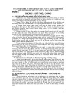
Figure 3.1 illustrates the different UMTS domains. The identified domains imply the
evolution of current or existing network infrastructures, but do not exclude new ones.
The Core Network (CN) domain can evolve for example from the GSM, N-ISDN, B-
ISDN, and PDN infrastructures.
bad
VrÃ@vrÃ9hv
6ppr
Irx
9hv
8rÃIrxÃ9hv
DshprÃ9hv
8
Hivyr
@vr
9hv
86,0
'RPDLQ
Uhv
Irx
9hv
V
D b`d
Trvt
Irx
9hv
Cr
Irx
9hv
8 2ÃSrsrrprÃvÃirrrÃVTDHÃhqÃH@
D 2ÃSrsrrprÃvÃirrrÃ6pprÃhqÃTrvtÃIrxÃqhv
V 2ÃSrsrrprÃvÃirrrÃVrÃ@vrÃhqÃDshprÃqhvÃVHUTÃhqvÃvrshpr
b`d 2ÃSrsrrprÃvÃirrrÃTrvtÃhqÃUhvÃIrxÃqhv
bad 2ÃSrsrrprÃvÃirrrÃTrvtÃhqÃCrÃIrxÃqhv
Figure 3.1 UMTS architecture domains and reference points.
42 The UMTS Network and Radio Access Technology
The generic architecture incorporates two main domains, i.e. the user equipment domain
and the infrastructure domain. The first concerns the equipment used by the user to
access UMTS services having a radio interface to the infrastructure. The second con-
sists of the physical nodes, which perform the various functions required to terminate
the radio interface and to support the telecommunication services requirements of the
users. The rest of the sub-domains are defined in Table 3.1.
Figure 3.16 in Appendix A illustrates the four (Application, Home, Serving, and Trans-
port) strata. It also shows the integrated UMTS functional flow, i.e. the interactions be-
tween the USIM, MT/ME, Access Network, Serving Network and Home Network do-
mains, including interactions between TE, MT, Access Network, Serving Network,
Transit Network domains and the Remote Party.
Table 3.1 The UMTS Architecture Domains
U
SER
E
QUIPMENT
D
OMAINS
: dual mode and multi-mode handsets, removable smart cards, etc.
Mobile Equipment
(ME) domain
Consists of:
The Mobile Termination (MT) entity performing the radio trans-
mission and related functions, and
the Terminal Equipment (TE) entity containing the end-to-end ap-
plication, (e.g. a laptop connected to a handset).
USIM domain The User Services Identity Modulo (USIM) domain contains data and
procedures to unambiguously and securely identify itself, (e.g. smart
card)
I
NFRASTRUCTURE
D
OMAINS
Access Network
(AN) domain
Consists of the physical entities managing the access network resources
and provides the users with mechanisms to access the core network
Core Network
(CN) domain
Consists of the physical entities providing support for the network fea-
tures and telecommunication services; e.g. management of user location
information, control of network features and services, switching and
transmission mechanisms for signalling and for user generated informa-
tion.
It includes:
1. Serving Network (SN) domain representing the core network func-
tions local to the user’s access point and thus their location changes
when the user moves.
2. Home Network (HN) domain representing the core functions con-
ducted at a permanent location regardless of the user’s access point.
The USIM is related by subscription to the HN.
3. Transit Network (TN) domain, which is the CN part between the
SN and the remote party.
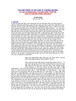
3.1.1.2 The IMT 2000 Family
The UMTS high level architecture integrates the physical aspects through the domain
concept and functional aspects through the strata concept. The separation according to
[1] allows a UMTS network to fit within the context of the IMT 2000 family of net-
works as illustrated in Figure 3.2.
Basically there are two CN options for the air interface of the IMT 2000 family of net-
works, i.e. GSM and IS-41 networks. The first one, which also includes the IP packet
The UMTS Development Platform 43
network, will serve the UTRA modes and the UWC-136 (packet) evolving based on
EDGE. While GPRS may become an IP core network on its own, where UMTS and
other air interfaces will directly connect to it, today it is part of the GSM infrastructure.
IS-41 will serve primarily USA regions in the evolution of IS-136 in TDMA and IS-95
in CDMA.
&RUH 1HWZR UNV*$LU,QWHUIDFHV
875 $
)'':&'0$
7''7'&'0$
&636
(YROYLQJFRUHV
8:&('*(
,6&25(
&'0$
0XOWLFDUULHU
,:)
0$3
,6
*356
,3&25(
*60
Figure 3.2 The IMT 2000 family of networks.
3.1.2 Coexistence of Present and Future Networks
While UMTS will bring new services and allow new access options, its deployment and
introduction will be in several phases. The first no doubt will evolve within a mixed
environment where coexistence with 2nd generation systems like GSM (including
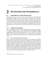
GPRS) will be predominant. Figure 3.3 illustrates the main network elements of a typi-
cal GSM network incorporating the Circuit Switched (CS) segment and the GPRS enti-
ties as part of the Packet Switched (PS) segment. It also includes the future UMTS ele-
ments on the radio interface side. Hence while some operators or service providers will
deploy completely new network infrastructures, others will use GSM architecture as the
basis for UMTS or 3G systems. This means that UMTS will complement the existing
GSM system in some cases, not replace it.
Clearly for all the elements to coexist as illustrated in Figure 3.3 they must all contain
the necessary HW/SW (including protocols) enabling features for inter-working. Today,
for example, the SMG (ETSI) and 3GPP organization have the task of making 2nd and
3rd generation elements inter-work seamlessly through specification and recommenda-
tions. The technical specifications for practical reasons are issued in releases, e.g. the
contents of the 1st edition of this book will be based on Release 1999 covering the evo-
lution of GSM and the introduction of UMTS.
44 The UMTS Network and Radio Access Technology
%76
%6&
6*61
**61
Dhr
66
1:
606&
+/5
&*
%LOOLQJ
6\VWHP
*356
%DFNERQH
,31HWZRUN
DrQGHI
Irx
BhrhÃBQST
TÃIqr
Avrhyy
TrvtÃBQST
TÃIqr
7qr
Bhrh
8uhtvt
Bhrh
CrÃGphv
Srtvr
TuÃHrhtr
TrvprÃ8rr
Grthy
,QWHUFHSW
Drr
9IT
9hvÃIhr
Tr
Q8V
Drthrq
PÃÉÃH
*
E
*
U
*
V
*
G
*
G
*
U
*
V
*
L
*
L
*
Q
*
Q
*
S
([LVWLQJ&LUFXLW
6ZLWFKHG&61HWZRUN
3DFNHW6ZLWFKHG361HWZRUN
06&
9/5
166
%66
*356
3671
1HWZRUN
%*
5
1
&
%76
%76
VHUTÃÃVUS6I
)XWXUH$LU,QWHUIDFH
(QKDQFHPHQWV
('*(
%76
BTHÃhqÃVHUT
Chqr
,
X
36
,
X
&6
Figure 3.3 Coexistence of 2nd and 3rd generation mobile network elements.
3.2 T
HE
C
ORE
N
ETWORK
D
OMAIN
3.2.1 Network Evolution Towards UMTS
Evolution here implies seamless and dynamic interoperability of 2G (2.5G) and 3G
technologies in the Core Network (CN) and Radio Network (RN) sides. We will thus
cover these evolution implications next taking into account the integrated network ele-
ments illustrated in Figure 3.3, i.e. the PS and CS building blocks in the CN side and
UTRAN and EDGE in the RN side.
To structure the presentation following the domain concept, we first cover the core net-
work domain. Forthcoming chapters address the access network and mobile equipment
The UMTS Development Platform 45
domains. Furthermore, for completeness we also define the basic functions of the CN
building blocks.
The UMTS platform as illustrated in Figure 3.3, will incorporate a number of 2G/3G
1
functional elements joined by standard interfaces. Together these network elements will
route multifarious information traffic and provide:
resource allocation;
mobility management;
radio link management;
call processing;
billing record generation;
operational and maintenance functions; and
collection of performance statistics.
The CN comprises of circuit and packet switching systems, trunk transmission, signal-
ling systems, the access network and service platforms.
Figure 3.4 highlights the 3G side represented in layers to point out some of the new
elements incorporated to the legacy GSM network. Each layer contains a distinct net-
work element based on the CN infrastructure evolution. However, it is not restricted to
the CN layers, it includes, e.g. the radio layer and others as follows:
the radio network layer illustrating new WCDMA base stations (BSs) and the RNC
to be described in Chapter 4;
the mobile switching layer, which regroups the 3G SGSN, 3G MSCs with their
upgraded associated components, such as HLR, VLR, AuC, EIR, and their new
CPS unit enabling IP telephony;
the transit–IP layer, which not only serves as the backbone layer for transiting traf-
fic between nodes, but also incorporates the IP bypass mediation device for signal-
ling and user data between CS and PS. The GGSN may is also part of this layer.
the signalling layer, comprising mainly of STPs connected to the other elements;
the management layer composed of the integrated network management systems
and network mediation systems as illustrated in Figure 3.3;
the service layer will comprise all value-added service platforms, such as SMC,
VMS, intelligent network platform and customer care centres, ISP, billing platform,
etc;
_______
1
GSM 1800 MHz evolving elements and new UMTS or 3G specific elements co-existing seamlessly.
46 The UMTS Network and Radio Access Technology
VUS6Ã7T
51&
*06&
+/5
TBTI
BBTI
6&3
D
D
H6Q
8
6
Q
DTVQ
Bv
B
"B7UT
H
6
Q
86Q
DQÃApv
*:
3671*60
1HWZRUN
L,3
1:
6
L
J
Q
D
O
O
L
Q
J
/
D
\
H
U
0
D
Q
D
J
H
P
H
Q
W
/
D
\
H
U
6
H
U
Y
L
F
H
/
D
\
H
U
ShqvÃIrxÃGhr HivyrÃTvpuÃGhr UhvÃÃDQÃGhr
Figure 3.4 Representation of the CN and radio access layers.
For background completeness on the CN side, the main GPRS elements and terminal
connections to a GPRS network are described next from the functional level.
3.2.1.1 Main Packet Switched Network Elements
The Serving GPRS Support Node (SGSN) performs the following key tasks:
authentication and mobility management;
protocol conversion between the IP backbone and the protocols used in the BSS
and MS;
collection of charging data and traffic statistics;
routing data to the relevant GGSN when connection to an external network is re-
quired (all intra-network MS to MS connections must also be made via a GGSN).
The Gateway GPRS Support Node (GGSN) acts as the interface between the GPRS
network and external networks; it is simply a router to a sub-network. When the GGSN
receives data addressed to a specific user, it checks if the address is active. If it is, the
GGSN forwards the data to the SGSN serving the mobile: if the address is inactive the
data is discarded. The GGSN also routes mobile originated packets to the correct exter-
nal network.
3.2.1.1.1 Terminal Attachment to the GPRS Network
The connection between a GPRS terminal and the network has two parts:
The UMTS Development Platform 47
1. Connection to the GSM network (GPRS Attach) – When the GPRS terminal is
switched on, it sends an ‘attach’ message to the network. The SGSN collects the user
data from the HLR and authenticates the user before attaching the terminal.
2. Connection to the IP network (PDP context) – Once the GPRS terminal is attached, it
can request an IP address (e.g. 172.19.52.91) from the network. This address is used to
route data to the terminal. It can be static (the user always has the same IP address), or
dynamic (the network allocates the user a different IP address for each connection).
Dedicated standard (ETSI specified) interfaces assuring the interconnection between the
key network elements and enabling multi-vendor configurations include:
Gb-interface (SGSN-BSS);
Gn-interface (GSN-GSN);
Gp-interface (inter-PLMN interface);
Gi (GGSN-external IP networks);
Gr (SGSN-HLR);
Gs (SGSN-MSC/VLR);
Gd (SGSN to SMS-GMSC/SMS-IWMSC).
Other GPRS elements illustrated in Figure 3.3 are:
1. Domain Name Servers – These are standard IP devices that convert IP names into
IP addresses e.g. vms.orange.ch
172.19.52.92
2. Firewalls – These protect the IP network against external attack (e.g. from hack-
ers). The firewall might reject all packets that are not part of a GPRS subscriber ini-
tiated connection.
3. Border Gateway – This is a router providing, e.g. a direct GPRS tunnel between
different operators’ GPRS networks via an inter-PLMN data network, instead via
the public Internet.
4. Charging Gateway – GPRS charging data are collected by all the SGSNs and
GGSNs in the network. The charging gateway collects all this data together, proc-
esses it and passes it to the billing system.
3.2.1.2 Open Interfaces
To practically visualize the inter-operating environment we will take as reference a
GSM Network in transition towards a 3G system.
Evolving CN elements, e.g. will concurrently support interfaces (thereby signalling) for
both 2G and 3G radio networks, i.e. existing elements will be enable through field up-
grades with Iu interface towards high-capacity 3G.
48 The UMTS Network and Radio Access Technology
The 3G RAN, e.g. will connect to a GSM CN via the Iu interface. This interface pro-
vides a logical separation between CS and PS signalling giving the possibility to physi-
cally separate the interfaces, i.e.
Iu–CS interface for circuit-switched traffic, based on the ATM transport protocol,
and
Iu–PS interface for packet-switched traffic, based most likely on IP over ATM.
The Iu interfaces above assume that: the MSC can also multiplex the Iu–PS interface to
the SGSN with only one physical interface from RNC to the core network, and that the
MSC will get an ATM module to interact with the ATM based RAN.
A second new interface besides the Iu in the CN concerns IP links. It is foreseen that by
the time UMTS is deployed, MCSs will support IP connections. Thus the solution can
be envisaged as follows:
a new feature in the MSC, will be the integrated IP function protocol between two
MSCs signalling and user data between CS and PS;
the integrated IP function will introduce a new type of trunk signalling to the MSC
switching system, i.e. SS7 over the IP network;
the transmission over the IP network will be done using the User Datagram Proto-
col (UDP) from the TCP/IP stack; both signalling transmission and media transmis-
sion will use the protocol;
data, fax and compressed speech will be packetized to IP packets and transmitted to
the other switch using the Real-Time Transport Protocol (RTP) on the UDP.
Other key interfaces in the evolution to 3G include:
A-Interface MSC to GSM BSS will continue as needed for applications like Radio
Resource Management (RRM), Mobility Management (MM), and Link Manage-
ment (LM);
MAP performing signalling between the MSC and other NSS elements and per-
forming critical operations between switching and database elements to support
roaming;
CCS7 – Common Channel Signalling system (7) links the MSC to a PSTN or to an
ISDN using a single channel to carry the signalling of multiple speech circuits; the
digital Channel Associated Signalling (CAS) used between exchanges will also
continue as needed;
in the short term, the File Transfer Access and Management (X.25 FTAM) inter-
face will continue to communicate with billing systems as IP links to new billing
centres develop;
standard V.24 interfaces connecting O&M terminals to the MSC will probably con-
tinue, while more sophisticated WWW type interfaces will be implemented with
evolving MSC operating systems.
The UMTS Development Platform 49
In conclusion, we can say that the two critical interfaces that UMTS introduces to the
CN are primarily the Iu and IP. These interfaces add new dimension to the existing
GSM infrastructures besides enriching the type of links a CN may have.
In the following we cover the essential transition steps in terms of the 3G architecture
requirements.
3.2.2 Key Release 99 Architectural Requirements
The general working assumptions for Release 99 (R99), which cover the phase 1
UMTS/Release ’99 GSM standards and reflecting in part the elements illustrated in
Figure 3.3, can be summarized from [3] as follows:
a Core Network based on an evolved 2G MSC and an evolved SGSN
an optionally evolved Gs interface
Mobile IPv4 with Foreign Agent (FA) care-of addresses to end-users over the
UMTS/GPRS network, where the FA is located in the GGSN.
class A GSM mobiles.
Transcoder location shall be according to the “Evolution of the GSM platform to-
wards UMTS” outlined in 3G TS 23.930
UMTS/IMT 2000 Phase1 (R99) network architecture and standards shall allow the
operator to choose between Integrated and Separated CNs for transmission (includ-
ing L2)
The UMTS standard shall allow for both separated and combined MSC/VLR and
SGSN configurations.
The UE shall be able to handle separated or combined MSCs and SGSNs.
There can be several user planes to these CN nodes.
The following general concepts should be followed:
Separate the layer 3 control signalling from the layer 2 transport discussion (do not
optimize layer 3 for one layer 2 technology).
MSC-MSC layer 3 call control is out of scope of standardization in SMG.
As future evolution may lead to the migration of some services from the CS do-
main to the PS domain without changes to the associated higher-layer protocols or
functions. UMTS release 99 shall provide the flexibility to do this in a way that is
backwards compatible with release 99 UEs, provided this does not introduce sig-
nificant new complexity or requirements in the system.
3.2.3 The R99 Core Network Synthesis
In the preceding section we have already covered the evolution of the CN. However,
here we are summarizing them again in the light of the R99 to provide a concise back-
ground for R00 introduced in Chapter 9. The synthesis here considers the classical 2G
(GSM) type CN architecture evolving to 3G CN. However, some suppliers may already
50 The UMTS Network and Radio Access Technology
use the layered architecture as illustrated in Chapter 7, to introduce R99 and directly
evolve into R00 with minimum or no structural changes.
The UMTS R99 CN will start with a hybrid GSM network. Thus real-time services such
as voice and video will continue the usage of CS paths through the Mobile Switching
Centre (MSC). Non real-time services, e.g. Internet type (email, ftp, information ser-
vices, etc.), will also continue passing through the GPRS network.
While IP services may appeal to both, public and private, the latter may exploit more IP
services such as IP telephony, person-to-person multimedia conferencing, mobile Inter-
net, etc; CS voice telephony may initially remain the best solution for the mass market.
On the other hand, if end-to-end mobile IP telephony consolidates its flexibility with
minimized cost and high quality and IP native terminals are widespread, the mass mar-
ket may embrace IP services very rapidly.
7T8
QTUIDT9I
TBTI
BBTI
SI8
,X&6
$
*E
,X36
DrrÃÉ
phrÃDQ
IrÃI@
"BÃHT8
CGS
@yvt
ÃI@
Figure 3.4b 2G Elements evolving for UMTS R99.
Figure 3.4b illustrates the evolving CN elements to meet the R99 specificationss. Notice
that the evolution affects primarily the SGSN, MSC, and HLR. These elements will
either have new architecture platforms or follow SW upgrade with selected HW addi-
tions. The process will vary from supplier to supplier. The new element, i.e. RNC, cor-
responds to the radio network. For completeness we next review the main functions and
transition steps of the CS and PS network elements. The Value Added Services (VAS)
platforms (e.g. voice mail, SMSC, IN, pre-paid, etc.), which also reside in the CN, will
evolve at their own pace.
3.2.4 Circuit Switched (CS) Network Elements (NE)
3.2.4.1 The 3G Mobile Switching Centre (3GMSC)
The 3G MSC will become the main element of the R99 CS network just as it is in GSM.
In general depending on the manufacturers, a 3G MSC will include a VLR and a SSP to
serve both GSM BSS and 3G RAN concurrently by incorporating both A and Iu inter-
The UMTS Development Platform 51
faces. The Iu interface will be realized through a HW upgrade, e.g. a plug-in board to
the MSC in some cases, or an ATM module using a new HW platform connecting to the
MSC in other cases. Thus, the same 3GMSC will control services and charging for CS
2G/3G services in seamless co-existence. Furthermore, some 3GMSCs will interconnect
through IP interfaces and multiplex Iu traffic from the RNC.
3.2.4.1.1 ATM Functionality
For all practical purposes we assume here that the ATM functionality takes place in a
dedicated element, which we will call the ATM unit. This unit will have as a primary
function to provide inter-working of the 3GMSC with the UMTS Radio Access Net-
work (UTRAN) In most cases this unit will also provide transcoding functions for 3G
CS services. The ATM unit will then support:
Iu interface for ATM transmission in the UTRAN side and TDM transmission in
the MSC side
speech transcoding and user plane adaptation for CS data services
3G to 2G protocol conversion (e.g. WCDMA RANAP and GSM BSSAP).
3.2.4.2 The 3G Home Location Register
In most cases the 3GHLR will evolve from the 2GHLR through SW upgrade, i.e. the
same HLR (including e.g. AuC and EIR) will serve 2G/3G dual-mode users with cen-
tralized subscriber information. Thus, service providers will use only one centre to acti-
vate 2G subscribers (e.g. GSM voice or GPRS) and UMTS subscribers with all their
different traffic profiles. The 3GHLR then stores:
subscriber profile data for 2G and 3G services
subscriber identity
semi-dynamic information, e.g. current subscriber profile with activated ser-
vices, etc.
dynamic data, e.g. mobility management data.
authentication information
equipment identity info specifying listed mobile equipment identities.
3.2.4.3 New Services
While expected CS services may have rates up to 384 kbps, initial new services may
start first with 64 and 144 kbps. Among these services sets we will have, e.g.:
Virtual Home Environment (VHE): comprehensive set of services, features and
tools, which have the same look and feel at home or abroad
new bearer service defined by QoS parameters and a toolbox for implementing
operator specific services
52 The UMTS Network and Radio Access Technology
roaming between 2G/3G network, i.e. UMTS and GSM will be supported as well
as handovers from one network to another
enhanced location services, i.e. new multimedia applications will be possible with
the higher rate transmissions (e.g. real time video displays, dynamic broadcasting
and easy banking).
When comparing to GSM, e.g. in practice the new evolved NEs will then be capable of:
providing multiple service components in one stream to a single user terminal si-
multaneously for multimedia, thus offering transparency for video communications
offering high bit rates for both circuit- and packet-switched bearer services
offering multiple connections concurrently to single user MS to serve speech +
packet data for example.
In addition, during the transition to full IP CN e.g. only the CS part will be able to sup-
port services requiring constant bit rate with small delay variations through the proto-
col/rate adaptation conversion carried out by the ATM unit. Thus, the 3G NEs will sup-
port 64
2
to 384 kbps transparent or real-time CS data services easily.
3.2.5 Packet Switched (PS) Network Elements (NE)
3.2.5.1 3G Serving GPRS Support Node (3G SGSN)
As illustrated in Figure 3.4b, for UMTS R99 the SGSN will require an evolution to 3G
SGSN to successfully support 3G PS services. This evolution becomes imperative to
acts as a link between the 3G Radio Access Network (RAN) and the packet core, in
order to perform both control and traffic handling (gateway) functions for the PS do-
main part of the 3G system. An evolved SGSN or a 3G SGSN will then provide:
an interface between the Radio Network Controller (Iu) and the 3G Core Network
(Gn, Gp). The physical Iu interface will generally use an ATM STM-1 optical in-
terface, while the Gn and Gp physical interfaces can use Ethernet or ATM technol-
ogy.
SS7 network interface to communicate with the HLR (Gr), EIR (Gf) and the SMSC
(Gd). Some may use X.25 or IP to connect the SMSC. The physical SS7 interfaces
for Gf, Gr and Gd will generally use E1-PCM or T1-PCM connections.
interface with the charging gateway through the Ga interface.
2WKHU IXQFWLRQVRI WKH *6*61 VRPH PD\ GHSHQGRQ WKH PDQXIDFWXUHUV URDG PDS
LQFOXGH,3YPRELOLW\PDQDJHPHQW VHVVLRQPDQDJHPHQW 4R6PXOWLSOH3'3FRQWH[W
SHU,3DGGUHVVWXQQHOOLQJFKDUJLQJ,36HFODZIXOLQWHUFHSWLRQ606SUHSDLG
_______
2
With UDI ISDN H.324 inter-working for example.
The UMTS Development Platform 53
3.2.5.1.1 Functional Characteristics GPRS and the 3G SGSN
As noted above, the 3G SGSN and the 2G SGSN do have some capital differences
when it comes to functionality. If we pair them with the RNC and BSC, respectively,
we can see the different functions in Table 3.1b.
Table 3.1b The 2G- and 3G-SGSN functional characteristics
3G SGSN RNC 2G SGSN BSC
Mobility management X X X
Interaction with HLR, MSC/HLR X 3G MSC only X
Charging and statistics X X
High capacity routing X
IP telephony X X
Real time multimedia X X
Authentication X X
Radio protocol to IP conversion X X
GTP tunnelling to GGSN X X
Ciphering X X
Compression X X
While there remains similarities between the 2G/3G SGSNs, major differences also
exist, e.g. ciphering and compression no longer takes place at the 3G SGSN but at the
RNC. Mobility management takes place in the 3G SGSN and the RNC. Before, the
BSC did not perform any of these functions. 3G SGSN will support delay sensitive ap-
plications, e.g. IP telephony and real time multimedia requiring high capacity routing;
these functions did not take place at the 2G SGSN. Thus, migration to the 3G SGSN has
added some functions with demand for higher processing capacity.
3.2.5.2 The Gateway GPRS Support Node (GGSN)
A 2G GGSN in most cases will not need structural changes besides probably a SW up-
grade to support 3G. In any case, it acts as an interface between the GPRS/3G network
and external networks. It connects the GPRS and 3G core to the Internet world, ISPs
and private or corporate Intranets, thereby allowing 2G (GPRS) and 3G mobile users to
have data services. On the other hand, because we see the GGSN as a router from exter-
nal networks, major changes will occur only with additional unique functions. Other
common functions, depending also on the manufacturer’s road map as in the SGSN, can
be listed as follows:
integrated support for GPRS and 3G
support for multiple access points per GGSN and multiple PDP contexts per IP
address
Ipv6 and QoS
support standard routing protocols, e.g. RIPv1-v2, OSPF, IGRP, BGP4, DVMPR,
including static routing
54 The UMTS Network and Radio Access Technology
IPSec and lawful interception
prepaid, hot billing, fixed rate charges, CDR consolidation
3
and duplicate CDR
removal.
3.2.5.3 Charging, Border and Lawful Interception Gateways
No changes in the intrinsic functions of the CG, BG, and LIG occurred for 3G. Thus,
charging, e.g. takes place as in GPRS, i.e. charging data gets collected by all the SGSNs
and GGSNs in the network.
For the Border Gateway (BG) we will continue using the Public Land Mobile Network
(PLMN) solutions based on roaming agreements between operators. Hence, main tasks
such as providing a secure connection between PLMNs over the Inter-PLMN backbone
network will continue.
The Lawful Interception Gateway (LIG) will also remain essential for network func-
tionality in the 3G infrastructure, allowing authorities to monitor and intercept 3G mo-
bile data calls. Therefore, providers around the globe will be able to meet their local
authority requirements before starting commercial 3G services.
3.2.5.4 DNS, DHCP and the IP Backbone
As in the preceding elements, the DNS, DHCP and IP backbone does not need unique
functions for 3G.
For example, with 3G, DNS will continue allowing the SGSNs to translate logical
names into physical addresses of the GSNs. The 3G SGSN will thus use the DNS server
to determine the IP address of the GGSN when activating a PDP context and to find the
address of the SGSN when doing an inter-SGSN routing area update. The principle of
two DNS servers, one primary and one secondary (backup DNS server) will also con-
tinue.
The Dynamic Host Control Protocol (DHCP) in GPRS and 3G also has the same func-
tion; i.e. it automates IP address management. In GPRS as well as 3G static IP address
allocation will take place in the HLR and dynamic IP address allocation will come ei-
ther from RADIUS/DHCP servers within the private/corporate network or from the
GGSN’s internal addresses pool.
Finally, the IP backbone will continue, as in GPRS, with the only difference that higher
capacity LAN switches may be required.
3.2.5.5 Network Connectivity in the 3G Packet Core
We do not expect major change in network connectivity for 3G PS either. For example,
an access point (configured in the GGSN) will continue to be the logical connection
point that the GGSN will provide to allow MS to attach to external networks
4
. Sub-
_______
3
Putting together CDRs from various services.
4
A single access point always refers to a certain external network, e.g. a company Intranet or an ISP.
The UMTS Development Platform 55
scribers, e.g., will continue to use one access point in order to access their own ISP pro-
vider’s services, and a 2nd access point to connect to the private/corporate Intranet. In
general, the configuration parameters for an access point will include:
static IP address range or dynamic IP address pool for subscribers
set number of PDP contexts for the access point
dedicated RADIUS server addresses and passwords (e.g. authentication and ac-
counting)
DHCP server address and IP address allocation method (e.g. DHCP, GGSN,
RADIUS)
user authentication method (e.g. RADIUS) and default router.
To select the desired network access, the subscriber uses the Access Point Name (APN).
The SGSN uses the APN to resolve the IP address of the correct GGSN.
One GGSN can provide more than one access point on the same physical interface (e.g.
Ethernet port) when using tunnelling to separate data traffic routed to different net-
works. Likewise, we can link one access point to several GGSNs for redundancy or
resilient using a round robin approach.
3.2.5.6 Implementing Quality of Service (QoS)
QoS managed on a link by link basis, is also an inherent feature in 3G. Once the traffic
has been classified dedicated and integrated for example, where the first would require a
certain level of quality and the 2nd a certain bandwidth guaranteed, the process of im-
plementation will follow typical steps. The MS and the network negotiate and agree
QoS level during the PDP-context activation. However, based on the availability of
radio resources, it may also be re-negotiated later during the session. We can illustrate
these steps as follows:
The MS sends an active PDP context message to the SGSN containing, e.g. the
access point name and a number of other parameters including a QoS profile.
The SGSN verifies the request with the HLR based on the user’s subscription pro-
file. If there is contradiction, the QoS request may be rejected. Otherwise, the
SGSN will issue a DNS query to identify the IP address of the GGSN associated
with the requested access point.
The SGSN then issues a create PDP context request to the GGSN with the re-
negotiated QoS profile. The GGSN may accept or decline this request.
The GGSN replies with its acceptance of the PDP context request to the SGSN and
the SGSN in turn to the MS.
In the IP backbone, dedicated traffic for example, will make use of the Type of Service
(ToS) field in the IPv4 or Ipv6 header to classify traffic. Then the GGSN and SGSN
map the QoS profile requested in the PDP context activation message to dedicated code
points.
56 The UMTS Network and Radio Access Technology
We can also map dedicated classes to ATM Permanent Virtual Circuits (PVCs) to pro-
vide guaranteed QoS. However, this is still undergoing consolidation in the standardiza-
tion bodies, e.g. IETF.
We may also map dedicated classes to MPLS labels, where the latter defines a protocol
for encapsulating IP packets. MPLS, which has awareness of routing devices, uses a
four-byte label added to the original packets. Thus, MPLS aims to simplify routing de-
cisions by allowing packets to go along specific routes based on QoS parameters among
others.
3.2.5.7 Implementing Ipv6
The introduction of IP terminals in 3G will dramatically increase the need for new IP
addresses. Thus, we turn to IPv6 to enable new services and solve the problems inherent
with IPv4 networks. IPv6 offers an enlarged address space, e.g. in IPv4 the address
length is only 32 bits whereas IPv6 addresses have a length of 128 bits. These longer
addresses enable IPv6 to offer a total of 2
128
IP addresses.
The IPv6 protocol offers the following to 3G mobile networks, besides the enhanced
address range:
same IP address wherever you roam, i.e. global reachability
multifarious 3G services to the mass market
enhanced security through standardized and mandated security features
availability of IP addresses for billions of terminals
built-in QoS enhancing performance.
On the other hand, supporting IPv6 in 3G mobiles implies changes in various elements
of the 3G network, and this may not come from all equipment manufacturers at the
same time, or may not happen inR99. These changes include:
the HLR and SGSN will need SW upgrades to support IPv6 parameters
the GGSN will need to support IPv6 protocol stack in its external interfaces (i.e.
Gi)
the MSs will need the IPv6 protocol stack.
Since the subscriber’s IPv6 traffic would be carried over the 3G backbone within the
GTP tunnels, it is not expedient that all the backbone routers, or even the SGSN proto-
col stacks, migrate from the start to IPv6. On the other hand, even if IPv6 capable MSs
could still use IPv4 backbones because of the GTP Tunneling Protocol that separates
the backbone IP layer from the subscriber IP packet payload; IPv6 will still benefit the
backbone layer, e.g. from the build in security features.
3.2.6 Coexistence Interoperability Issues
Although it seems that only one new interface, i.e. Iu, appears when incorporating the
UMTS radio network to the 2G or 2.5G CN, inter-networking impacts spread to all the
The UMTS Development Platform 57
integrated network elements as shown in Figure 3.3. In particular, mobility management
and call control bring in new interoperability requirements. These requirements are
summarized next before we concentrate on describing the different UMTS building
blocks of the radio network in forthcoming chapters.
3.2.6.1 Iu Interface Inter-Working Characteristics
The Iu principles presented in [5] apply to PS and CS networks. In this context,
UTRAN supports two logically independent signalling flows via the Iu interface to
combined or separated network nodes of different types like MSC and SGSN [3].
Thus, UTRAN contains domain distribution function routing application independent
UE control signalling to a corresponding CN domain. The UE indicates the addressed
application type through a protocol discriminator for example. Then UTRAN maps this
onto a correct Iu instance to forward signalling. UTRAN services, including radio ac-
cess bearers, are CN domain independent, e.g. we can get speech bearer either through
the PS or CS core network. The Iu includes control and user planes.
Because only a RNC can identify the actual packet volume successfully transferred to a
UE, it indicates the volume of all not transferred downlink data to the 3G-SGSN so this
latter can correct its counter.
3.2.6.1.1 Iu Control Plane
Both PS and circuit CS domains use the Signalling Connection Control Part (SCCP)
protocol to transport Radio Access Network Application Part (RANAP) messages over
the Iu interface. Likewise, both SCCP and RANAP protocols comply with ITU-T rec-
ommendations. In R99, SCCP messages in CS domain use a broadband SS7 stack com-
prising MTP3b on top of SAAL-NNI. In the PS domain UMTS specs allow operators to
chose one out of two standardized protocol suites, i.e. broadband SS7 stack comprising
MTP3b on top of SAAL-NNI or IETF/Sigtran CTP protocol suite for MTP3 users with
adaptation to SCCP. Figure 3.5 illustrates the different RANAP stack options.
5$1$3
6&&3
6$$/11,
073E
,3
D@UATvthÃ8UQÃQpy
T88QHUQ"
ÃrÃqyr
Figure 3.5 Stack options in the RANAP protocol.
3.2.6.1.2 Iu User Plane
The user plane towards the IP domain works based on an evolved Gn interface, where
we achieve tunnelling of user data packets over the Iu interface through the user plane
part of GTP over UDP/IP. The tunnelling protocol corresponds to an evolution of the
user plane part of the GTP protocol used in GPRS stacked on top of UDP/IP. When