Tài liệu Modules and Ports part 1 docx
Bạn đang xem bản rút gọn của tài liệu. Xem và tải ngay bản đầy đủ của tài liệu tại đây (25.35 KB, 5 trang )
[ Team LiB ]
4.1 Modules
We discussed how a module is a basic building block in Chapter 2
, Hierarchical
Modeling Concepts. We ignored the internals of modules and concentrated on how
modules are defined and instantiated. In this section, we analyze the internals of the
module in greater detail.
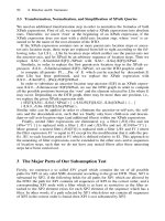
A module in Verilog consists of distinct parts, as shown in Figure 4-1
.
Figure 4-1. Components of a Verilog Module
A module definition always begins with the keyword module. The module name, port
list, port declarations, and optional parameters must come first in a module definition.
Port list and port declarations are present only if the module has any ports to interact with
the external environment.The five components within a module are: variable declarations,
dataflow statements, instantiation of lower modules, behavioral blocks, and tasks or
functions. These components can be in any order and at any place in the module
definition. The endmodule statement must always come last in a module definition. All
components except module, module name, and endmodule are optional and can be mixed
and matched as per design needs. Verilog allows multiple modules to be defined in a
single file. The modules can be defined in any order in the file.
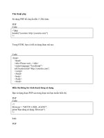
To understand the components of a module shown above, let us consider a simple
example of an SR latch, as shown in Figure 4-2
.
Figure 4-2. SR Latch
The SR latch has S and R as the input ports and Q and Qbar as the output ports. The SR
latch and its stimulus can be modeled as shown in Example 4-1
.
Example 4-1 Components of SR Latch
// This example illustrates the different components of a module
// Module name and port list
// SR_latch module
module SR_latch(Q, Qbar, Sbar, Rbar);
//Port declarations
output Q, Qbar;
input Sbar, Rbar;
// Instantiate lower-level modules
// In this case, instantiate Verilog primitive nand gates
// Note, how the wires are connected in a cross-coupled fashion.
nand n1(Q, Sbar, Qbar);
nand n2(Qbar, Rbar, Q);
// endmodule statement
endmodule
// Module name and port list
// Stimulus module
module Top;
// Declarations of wire, reg, and other variables
wire q, qbar;
reg set, reset;
// Instantiate lower-level modules
// In this case, instantiate SR_latch
// Feed inverted set and reset signals to the SR latch
SR_latch m1(q, qbar, ~set, ~reset);
// Behavioral block, initial
initial
begin
$monitor($time, " set = %b, reset= %b, q= %b\n",set,reset,q);
set = 0; reset = 0;
#5 reset = 1;
#5 reset = 0;
#5 set = 1;
end
// endmodule statement
endmodule
Notice the following characteristics about the modules defined above:
•
In the SR latch definition above , notice that all components described in Figure 4-
1 need not be present in a module. We do not find variable declarations, dataflow
(assign) statements, or behavioral blocks (always or initial).
•
However, the stimulus block for the SR latch contains module name, wire, reg,
and variable declarations, instantiation of lower level modules, behavioral block
(initial), and endmodule statement but does not contain port list, port declarations,
and data flow (assign) statements.
•
Thus, all parts except module, module name, and endmodule are optional and can
be mixed and matched as per design needs.
[ Team LiB ]
[ Team LiB ]
4.3 Hierarchical Names
We described earlier how Verilog supports a hierarchical design methodology. Every
module instance, signal, or variable is defined with an identifier. A particular identifier
has a unique place in the design hierarchy. Hierarchical name referencing allows us to
denote every identifier in the design hierarchy with a unique name. A hierarchical name
is a list of identifiers separated by dots (".") for each level of hierarchy. Thus, any
identifier can be addressed from any place in the design by simply specifying the
complete hierarchical name of that identifier.
The top-level module is called the root module because it is not instantiated anywhere. It
is the starting point. To assign a unique name to an identifier, start from the top-level
module and trace the path along the design hierarchy to the desired identifier. To clarify
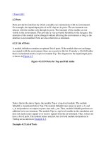
this process, let us consider the simulation of SR latch in Example 4-1
. The design
hierarchy is shown in Figure 4-5
.
Figure 4-5. Design Hierarchy for SR Latch Simulation
For this simulation, stimulus is the top-level module. Since the top-level module is not
instantiated anywhere, it is called the root module. The identifiers defined in this module
are q, qbar, set, and reset. The root module instantiates m1, which is a module of type
SR_latch. The module m1 instantiates nand gates n1 and n2. Q, Qbar, S, and R are port
signals in instance m1. Hierarchical name referencing assigns a unique name to each
identifier. To assign hierarchical names, use the module name for root module and
instance names for all module instances below the root module. Example 4-8
shows
hierarchical names for all identifiers in the above simulation. Notice that there is a dot (.)
for each level of hierarchy from the root module to the desired identifier.
Example 4-8 Hierarchical Names
stimulus stimulus.q
stimulus.qbar stimulus.set
stimulus.reset stimulus.m1
stimulus.m1.Q stimulus.m1.Qbar
stimulus.m1.S stimulus.m1.R
stimulus.n1 stimulus.n2
Each identifier in the design is uniquely specified by its hierarchical path name. To
display the level of hierarchy, use the special character %m in the $display task. See
Table 3-4
, String Format Specifications, for details.
[ Team LiB ]