Tài liệu Timing and Delay part 1 pdf
Bạn đang xem bản rút gọn của tài liệu. Xem và tải ngay bản đầy đủ của tài liệu tại đây (14.81 KB, 4 trang )
[ Team LiB ]
10.1 Types of Delay Models
There are three types of delay models used in Verilog: distributed, lumped, and pin-to-
pin
(path) delays.
10.1.1 Distributed Delay
Distributed delays are specified on a per element basis. Delay values are assigned to
individual elements in the circuit. An example of distributed delays in module M is
shown in Figure 10-1
.
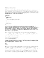
Figure 10-1. Distributed Delay
Distributed delays can be modeled by assigning delay values to individual gates or by
using delay values in individual assign statements. When inputs of any gate change, the
output of the gate changes after the delay value specified. Example 10-1
shows how
distributed delays are specified in gates and dataflow description.
Example 10-1 Distributed Delays
//Distributed delays in gate-level modules
module M (out, a, b, c, d);
output out;
input a, b, c, d;
wire e, f;
//Delay is distributed to each gate.
and #5 a1(e, a, b);
and #7 a2(f, c, d);
and #4 a3(out, e, f);
endmodule
//Distributed delays in data flow definition of a module
module M (out, a, b, c, d);
output out;
input a, b, c, d;
wire e, f;
//Distributed delay in each expression
assign #5 e = a & b;
assign #7 f = c & d;
assign #4 out = e & f;
endmodule
Distributed delays provide detailed delay modeling. Delays in each element of the circuit
are specified.
10.1.2 Lumped Delay
Lumped delays are specified on a per module basis. They can be specified as a single
delay on the output gate of the module. The cumulative delay of all paths is lumped at
one location. The example of a lumped delay is shown in Figure 10-2
and Example 10-2.
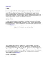
Figure 10-2. Lumped Delay
The above example is a modification of Figure 10-1
. In this example, we computed the
maximum delay from any input to the output of Figure 10-1, which is 7 + 4 = 11 units.
The entire delay is lumped into the output gate. After a delay, primary output changes
after any input to the module M changes.
Example 10-2 Lumped Delay
//Lumped Delay Model
module M (out, a, b, c, d);
output out;
input a, b, c, d;
wire e, f;
and a1(e, a, b);
and a2(f, c, d);
and #11 a3(out, e, f);//delay only on the output gate
endmodule
Lumped delays models are easy to model compared with distributed delays.
10.1.3 Pin-to-Pin Delays
Another method of delay specification for a module is pin-to-pin timing. Delays are
assigned individually to paths from each input to each output. Thus, delays can be
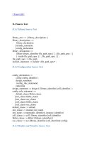
separately specified for each input/output path. In Figure 10-3
, we take the example in
Figure 10-1
and compute the pin-to-pin delays for each input/output path.
Figure 10-3. Pin-to-Pin Delay
Pin-to-pin delays for standard parts can be directly obtained from data books. Pin-to-pin
delays for modules of a digital circuit are obtained by circuit characterization, using a
low-level simulator like SPICE.
Although pin-to-pin delays are very detailed, for large circuits they are easier to model
than distributed delays because the designer writing delay models needs to know only the
I/O pins of the module rather than the internals of the module. The internals of the
module may be designed by using gates, data flow, behavioral statements, or mixed
design, but the pin-to-pin delay specification remains the same. Pin-to-
pin delays are also
known as path delays. We will use the term "path delays" in the succeeding sections.
We covered distributed and lumped delays in Section 5.2
, Gate Delays, and in Section
6.2, Delays. In the following section, we study path delays in detail.
[ Team LiB ]