Tài liệu Đo lường quang học P9 pdf
Bạn đang xem bản rút gọn của tài liệu. Xem và tải ngay bản đầy đủ của tài liệu tại đây (323.17 KB, 31 trang )
9
Photoelasticity and Polarized Light
9.1 INTRODUCTION
Up to now we have treated the light field as a scalar quantity. The electromagnetic
field, however, is a vector quantity which is perpendicular to the direction of propagation
and with a defined orientation in space. This property is known as the polarization of
light. In our treatments of interferometry and holography it is silently understood that
the interfering waves have the same polarization. In practice, however, this condition is
fulfilled to a greater or lesser degree. Unequal polarization of the interfering waves results
in a bias intensity which reduces the contrast of the fringes and, in the limit of opposite
polarization, we get no fringes at all. In analysing finer diffraction effects, the vector
property of the light must be taken into account, for example in the reconstruction of a
hologram (G
˚
asvik 1976). Special techniques have been used to reconstruct an arbitrary
state of polarization (Lohmann, Kurtz, G
˚
asvik). Although it is possible to get along quite
well with optical metrology without knowing anything about polarization, it is in many
cases very important to understand the vectorial properties of light.
In this chapter we learn how to describe polarization and we develop a useful formalism
based on Jones vectors and matrices. We also learn how to control and measure the state of
polarization by means of polarization filters. The points in a light path where the change in
polarization is most difficult to predict are at reflecting and refracting interfaces. Therefore
this subject is treated in Section 9.5. Finally, a specific optical measurement technique
is based on the light’s polarization. This technique, called photoelasticity, is described at
the end of this chapter.
9.2 POLARIZED LIGHT
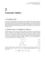
Consider a plane wave propagating in the z-direction. The field amplitude is a vector
denoted by
u = U e
ikz
(9.1)
of length U at an arbitrary angle φ to the x-axis, see Figure 9.1. The components along
the x-andy-axes therefore are
U
x
= U cos φ (9.2a)
U
y
= U sin φ (9.2b)
Optical Metrology. Kjell J. G
˚
asvik
Copyright
2002 John Wiley & Sons, Ltd.
ISBN: 0-470-84300-4
218
PHOTOELASTICITY AND POLARIZED LIGHT
y
z
x
U
x
U
y
U
f
Figure 9.1
We then have
u = [U
x
e
iδ
x
e
x
+ U
y
e
iδ
y
e
y
]e
ikz
(9.3)
where e
x
and e
y
are the unit vectors along the x-andy-axis respectively. By including
the phase constants δ
x
and δ
y
we have taken care of the fact that the two components may
not have the same phase. The factor e
ikz
we omit, since it merely gives the orientation of
the z-axis. Equation (9.3) then can be written as
u = e
iβ/2
[U
x
e
−iδ/2
e
x
+ U
y
e
iδ/2
e
y
]
= e
iβ/2
[u
x
e
x
+ u
y
e
y
] (9.4)
where
β = δ
x
+ δ
y
(9.5a)
δ = δ
y
− δ
x
(9.5b)
e
iβ/2
is a common phase factor which can be omitted since it does not affect the orientation
of u. This orientation, termed the direction of polarization or the state of polarization, is
therefore completely fixed by two independent quantities, i.e.
tan φ = U
y
/U
x
and δ (9.6)
The intensity of this wave is given as
I =|u|
2
= U
2
x
+ U
2
y
(9.7)
It is evident and easy to prove that the intensity always becomes equal to the sum of
the squares of the field components in a Cartesian coordinate system independent of the
orientation of the coordinate axes.
When such a polarized wave passes a fictional plane perpendicular to the z-axis, the
tip of the U -vector will in the general case describe an ellipse in that plane. A general
state of polarization is therefore termed ‘elliptically polarized light’. When δ =±π/2
and U
x
= U
y
, the ellipse degenerates to a circle and when δ = 0orπ to a straight
POLARIZING FILTERS
219
U
y
U
x
U
U
y
z
x
(a)
U
y
U
y
U
x
U
x
U
U
x
z
y
(b)
Figure 9.2 (a) Linear polarized light and (b) Circularly polarized light
line. These two special cases therefore represent so-called circular and plane (or linear)
polarized light respectively (see Figure 9.2). More specifically, δ =+π/2 represents right
circularly polarized light, whilst δ =−π/2 represents left circularly polarized light. This
has to do with the direction of rotation of the tip of the field vector.
9.3 POLARIZING FILTERS
To alter and to analyse the state of polarization of the light, one places in the beam
different types of polarization filters. Below, we consider the most important types.
9.3.1 The Linear Polarizer
A linear or plane polarizer (often called simply a polarizer) has the property of transmitting
light which field vector is parallel to the transmission direction of the polarizer only. The
field u
t
transmitted through the polarizer therefore becomes equal to the component of
the incident field onto this direction. If the incident wave U is plane-polarized at an angle
α to the transmission direction of the polarizer, we therefore have
u
t
= U cos α(9.8)
and the intensity
I
t
=|u
t
|
2
= U
2
cos
2
α(9.9)
Equation (9.9) is called Malus’ law.
220
PHOTOELASTICITY AND POLARIZED LIGHT
y
y
z
2
1
y
′
x
′
x
x
u
0
a
f
Figure 9.3
This is the case of an ideal polarizer with amplitude transmittances t
1
= 1andt
2
= 0
parallel to an normal to the transmission direction respectively. In a real polarizer, t
1
≤ 1
and t
2
≥ 0, but t
1
t
2
. Consider two such identical linear polarizers placed in tandem in
a light beam as shown in Figure 9.3. Here polarizer 1 has its transmission direction along
the x-axis while the transmission axis of polarizer 2 is inclined an angle α to the x-axis.
Assume that the wave field u
o
incident on polarizer 1 is linearly polarized at an angle φ
to the x-axis with amplitude equal to 1.
Then
u
o
= cos φe
x
+ sin φe
y
(9.10)
After passing polarizer 1, the field amplitude becomes
u
1
= t
1
cos φe
x
+ t
2
sin φe
y
(9.11)
To calculate the effect of polarizer 2, we first decompose u
1
into the coordinate system of
unit vectors e
x
, e
y
, along and normal to the transmission axis of polarizer 2 respectively:
u
1
= (t
1
cos φ cos α + t
2
sin φ sin α)e
x
+ (−t
1
cos φ sin α + t
2
sin φ cos α)e
y
(9.12)
After passing polarizer 2, the field amplitude becomes
u
2
= t
1
(t
1
cos φ cos α + t
2
sin φ sin α)e
x
+ t
2
(−t
1
cos φ sin α + t
2
sin φ cos α)e
y
(9.13)
and the intensity
I =|u
2
|
2
= (t
4
1
cos
2
φ + t
4
2
sin
2
φ)cos
2
φ
+ 2t
1
t
2
(t
2
1
− t
2
2
) sin φ cos φ sin α cos α + t
2
1
t
2
2
sin
2
α (9.14)
If the incident light is unpolarized (see Section 9.4), all polarization angles φ from 0 to π
will be equally represented. To find the transmitted intensity I
up
in this case, we therefore
have to average Equation (9.14) over this range of φ,i.e.
I
up
=
1
π
π
0
I dφ = (1/2)(T
2
1
+ T
2
2
) cos
2
α + T
1
T
2
sin
2
α(9.15)
where we have substituted the intensity transmittances T
1
= t
2
1
and T
2
= t
2
2
for the cor-
responding amplitude transmittances of the polarizer. Equation (9.15) can be regarded as
POLARIZING FILTERS
221
the generalized Malus law and can be used to determine T
1
and T
2
from measuring the
intensity at, for example α = 0
◦
and 90
◦
. Normally, T
1
and T
2
are wavelength dependent
and the ratio T
2
/T
1
is a measure of the quality of a linear polarizer. Values of T
2
/T
1
as
low as 10
−5
− 10
−6
can be reached with high-quality crystal polarizers.
A linear polarizer can be pictured as a grid of finely spaced parallel conducting metal
threads. When the field of the incident wave oscillates parallel to the threads, it will
induce currents in the threads. The energy of the field is therefore converted into electric
current, which is converted into heat and the incident wave is absorbed. Because of the
non-conducting spacings of the grid, currents cannot flow perpendicularly to the threads.
Fields oscillating in the latter direction will therefore not produce any current and the light
is transmitted. Although easy to understand, this type of polarizer is difficult to fabricate.
The most widely used linear polarizer is the polaroid sheet-type polarizer invented by
E. H. Land. It can be regarded as the chemical version of the metal thread grating. Instead
of long, thin threads it consists of long, thin molecules, i.e. long chains of polymeric
molecules that contain many iodine atoms. These long molecules are oriented almost
completely parallel to each other and because of the conductivity of the iodine atoms, the
electric field oscillating parallel to the molecules will be strongly absorbed.
Another type of linear polarizer is made from double-refracting crystals. Double-
refraction is a phenomenon where the incident light is split into two orthogonally linearly
polarized components. By proper cutting and cementing of such crystals, usually calcite,
one of the components is isolated and the other is transmitted, thereby giving a linear
polarizer. Other phenomena utilized for the construction of linear polarizers are reflection
and scattering.
9.3.2 Retarders
A retarder (or phase plate) is a polarization element with two orthogonal, characteristic
directions termed the principal axes. When light passes a retarder, the field compo-
nents parallel to the principal axes will acquire different phase contributions resulting
in a relative phase difference δ. This is due to the phenomenon of double-refraction or
birefringence which means that light fields oscillating parallel to the two principal axes
‘experience’ different indexes of refraction n
1
and n
2
. A retarder plate of thickness t
therefore produces a phase difference (retardance) equal to
δ = δ
2
− δ
1
= k(n
2
− n
1
)t (9.16)
Figure 9.4 sketches a retarder with the principal axes h
1
and h
2
parallel to the x-and
y-axis respectively. Consider a wave field U linearly polarized at an angle α to the x-axis
normally incident on the retarder. The transmitted wave u
t
then becomes
u
t
= U(cos αe
iδ
1
e
x
+ sin αe
iδ
2
e
y
)
= U e
i(δ
1
+δ
2
)/2
(cos αe
−iδ/2
e
x
+ sin αe
iδ/2
e
y
) (9.17)
Note that the intensity |u
t
|
2
= U
2
is unchanged by passing the retarder. In the case of
δ =±π/2 (9.18)
and cos α = sin α;i.e.α = 45
◦
, u
t
becomes circularly polarized.
222
PHOTOELASTICITY AND POLARIZED LIGHT
y
U
h
2
z
x
h
1
a
Figure 9.4
A retarder with δ =±π/2 is called a quarterwave plate because it corresponds to an
optical path length difference equal to λ/4 (cf. Equation (9.16)). The combination of a
linear polarizer followed by a quarterwave plate with their axes inclined at 45
◦
therefore
is termed a circular polarizer.
By putting δ = π, Equation (9.17) becomes
u
t
=−iUe
i(δ
1
+δ
2
)/2
(cos αe
x
− sin αe
y
)(9.19)
We see that the outcoming wave is linearly polarized and that the field vector is the
mirror image of the incoming field vector about the x-axis, i.e. the polarization angle has
changed by 2α. A retarder with δ =±π is called a halfwave plate because it corresponds
to an optical path-length difference equal to λ/2. A halfwave plate therefore offers a
convenient means for rotating the polarization angle of a linearly polarized light wave by
turning the axes of the halfwave plate by the desired amount.
A retarder is usually made from double-refracting crystals such as quartz or mica.
In contrast to the construction of linear polarizers, where one of the doubly refracting
components is isolated, both components are transmitted collinearly by proper cutting
and orientation of the crystal. A retarder can also be made from stretched sheets of
polyvinyl alcohol (PVA) in the same way as polaroids. In fact, cellophane sheets can be
used as a retarder.
In the retarders mentioned so far, the retardance δ is fixed by the plate thickness. It
would be highly desirable, however, to have a retarder in which the retardance could be
continuously varied. This can be done by a device called a Babinet–Soleil compensator
shown in Figure 9.5. Here two retarders of the same crystal of thicknesses t
1
and t
2
with
their axes inclined at 90
◦
are mounted together. The total retardance of the unit therefore
becomes proportional to the thickness difference t
1
− t
2
. The upper plate consists of two
wedges, one of which can be moved relative to the other, thereby varying the effective
thickness t
1
. This movement is controlled by a micrometer screw. The result is a retarder
with variable retardance which is uniform over the whole field of the compensator.
t
1
t
2
Figure 9.5 Babinet-soleil compensator
REFLECTION AND REFRACTION AT AN INTERFACE
223
y
z
x
Figure 9.6 Unpolarized light
9.4 UNPOLARIZED LIGHT
Light from ordinary light sources is said to be unpolarized. This is something of a mis-
nomer, but it means that the instantaneous direction of polarization will vary rapidly and
randomly in time between 0 and 2π. A common way of illustrating unpolarized light
propagating in the z-direction is as illustrated in Figure 9.6. This picture could be mis-
leading; a better illustration would be a collection of ellipses of random orientations and
eccentricities.
Mathematically, unpolarized light can be represented in terms of two arbitrary, orthog-
onal, linearly polarized waves of equal amplitudes for which the relative phase difference
varies rapidly and randomly. This aspect is strongly related to the coherence properties
of the light (see Section 3.3). By analogy with the degree of coherence, one also speaks
about the degree of polarization.
We shall not here go into any further details of this phenomenon. It should, however,
be easy to realize that unpolarized light will (1) be unaffected with regard to intensity
when transmitted through a retarder, and (2) become linearly polarized by transmitting
a linear polarizer, but with an intensity independent of the transmission direction of the
polarizer.
9.5 REFLECTION AND REFRACTION
AT AN INTERFACE
When light is incident at an interface between two media of different refractive indices,
both the reflected and the transmitted light will in general change its state of polarization
relative to the state of polarization of the incident light.
Consider Figure 9.7 where the light is incident from a medium of refractive index
n
1
, on a medium of refractive index n
2
. The incident light field is decomposed into the
components u
ip
and u
in
parallel and normal to the plane of incidence respectively. (The
plane of incidence is defined as the plane spanned by the surface normal at the point of
incidence and the incident light ray.) The corresponding quantities of the reflected light
are denoted u
rp
and u
rn
and their amplitudes U are related by
U
rp
= r
p
U
ip
(9.20a)
U
rn
= r
n
U
in
(9.20b)
224
PHOTOELASTICITY AND POLARIZED LIGHT
u
ip
u
rp
u
rn
u
tp
u
tn
u
in
n
1
n
2
q
1
q
2
q
1
Figure 9.7
where r
p
and r
n
are the amplitude reflection coefficients. These so-called Fresnel reflection
coefficients are given as
r
p
=
tan(θ
1
− θ
2
)
tan(θ
1
+ θ
2
)
(9.21a)
r
n
=
− sin(θ
1
− θ
2
)
sin(θ
1
+ θ
2
)
(9.21b)
where θ
1
= the angle of incidence and θ
2
= the angle of refraction. By using Snell’s law
of refraction (cf. Equation (1.16)) n
1
sin θ
1
= n
2
sin θ
2
, we get the following alternative
expressions for the reflection coefficients
r
p
=
n
2
cos θ −
n
2
− sin
2
θ
n
2
cos θ +
n
2
− sin
2
θ
(9.22a)
r
n
=
cos θ −
n
2
− sin
2
θ
cos θ +
n
2
− sin
2
θ
(9.22b)
where n = n
2
/n
1
, is the relative refractive index and where we also have dropped the
subscript 1 on the angle of incidence.
The corresponding amplitude transmission coefficients are given as
t
p
=
2sinθ
2
cos θ
1
sin(θ
1
+ θ
2
) cos(θ
1
− θ
2
)
(9.23a)
t
n
=
2sinθ
2
cos θ
1
sin(θ
1
+ θ
2
)
(9.23b)
REFLECTION AND REFRACTION AT AN INTERFACE
225
with the alternative expressions
t
p
=
2n cos θ
n
2
cos θ +
n
2
− sin
2
θ
(9.24a)
t
n
=
2cosθ
cos θ +
n
2
− sin
2
θ
(9.24b)
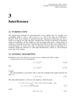
Figure 9.8 shows plots of r
p
and r
n
versus the angle of incidence for n = 1.52 (typically
for an air – glass interface). We see that r
p
= 0 at an angle of incidence equal to θ
B
.From
Equation 9.21(a) we see that this occurs when
θ
1
+ θ
2
= π/2 (9.25)
which, when inserted into Snell’s law gives
tan θ
B
=
n
2
n
1
(9.26)
θ
B
is called the polarization angle or the Brewster angle.
This is our reason for wearing polarization sunglasses. When the sunlight, which is
unpolarized, strikes a dielectric surface (like the sea) near the Brewster angle, the reflected
light becomes linearly polarized. When the transmission axis of the polarization sunglasses
is properly oriented, this specularly polarized reflected component will be blocked out.
As mentioned in Section 1.9, when light is incident from a medium of higher onto
a medium of lower refractive index, we get total internal reflection at the critical angle
1.0
0.8
0.6
0.4
0.2
0
Amplitude coefficients
−0.2
−0.4
−0.6
−0.8
−1.0
010203040
Angle of incidence q (degrees)
50 60 70 80 90
t
p
t
n
r
p
r
n
q
B
56.3
Figure 9.8 The amplitude coefficients r
p
, r
n
, t
p
and t
n
as a function of incident angle θ at a
dielectric interface (air-glass, n
2
/n
1
= 1.5)
226
PHOTOELASTICITY AND POLARIZED LIGHT
given by
sin θ
c
=
n
2
n
1
(9.27)
The field amplitude of a plane wave transmitted into the second medium can be described
by (see Equation (1.9))
u
t
= U
t
e
ik
2
(x sin θ
2
+z cos θ
2
)
(9.28)
When using Snell’s law we get
sin θ
2
=
n
1
n
2
sin θ
1
=
sin θ
1
n
(9.29a)
cos θ
2
=±
1 −
sin θ
1
n
2
(9.29b)
or, since we are concerned with the case where sin θ
1
>n
cos θ
2
=±i
sin θ
1
n
2
− 1 ≡±iβ(9.30)
Hence
u
t
= U
t
e
ik
2
x sin θ
1
/n
e
±k
2
βz
(9.31)
Neglecting the positive exponential which is physically untenable we have a wave whose
amplitude drops off exponentially as it penetrates the less dense medium. The field
advances in the x-direction as a so-called surface or evanescent wave. Notice that the
wavefronts or surfaces of constant phase (parallel to the yz-plane) are perpendicular to
the surfaces of constant amplitude (parallel to the xy-plane) and therefore the wave is said
to be inhomogeneous. Its amplitude decays rapidly in the z-direction, becoming negligible
at a distance into the second medium of only a few wavelengths.
Precautions should be taken when calculating the transmittance of the interface. Trans-
mittance is the ratio of the transmitted over the incident flux and is given by
T =
I
t
cos θ
2
I
i
cos θ
1
(9.32)
where the projected areas of the incident beams are taken into account since they are
unequal. Since u
i
and u
t
are propagating in media of different refractive indices we
must also take into account the correct proportionality factor between the field amplitude
squared and the irradiance, see Section 1.8, Equation (1.15). Then we get
I
t
I
i
=
n
2
|U
t
|
2
n
1
|U
i
|
2
(9.33)
and the transmittance
T =
n
2
cos θ
2
|U
t
|
2
n
1
cos θ
1
|U
i
|
2
=
n
2
cos θ
2
n
1
cos θ
1
t
2
(9.34)
THE JONES MATRIX FORMALISM OF POLARIZED LIGHT
227
Since both the incident and reflected beams are propagating in the same medium and their
projected areas are equal, we get for the reflectance
R = r
2
(9.35)
or in component forms
R
p
= r
2
p
(9.36a)
R
n
= r
2
n
(9.36b)
T
p
=
n
2
cos θ
2
n
1
cos θ
1
t
2
p
=
n
2
− sin
2
θ
cos θ
t
2
p
(9.36c)
T
n
=
n
2
cos θ
2
n
1
cos θ
1
t
2
n
=
n
2
− sin
2
θ
cos θ
t
2
n
(9.36d)
It can be shown that
R
p
+ T
p
= 1 (9.37a)
R
n
+ T
n
= 1 (9.37b)
as it should be.
9.6 THE JONES MATRIX FORMALISM
OF POLARIZED LIGHT
Equation (9.4) can be written in a more compact form as
|U=e
iβ/2
u
x
u
y
(9.38)
where
u
x
= U
x
e
−iδ/2
(9.39a)
u
y
= U
y
e
iδ/2
(9.39b)
|U is called a Jones vector or state vector, representing the state of polarization of the
wave. Evidently, the state of polarization, and thereby the Jones vector, remains unchanged
by a multiplicative constant. Therefore
|U
=c|U (9.40)
and |U are equal state vectors representing the same state of polarization. Equation (9.38)
can be decomposed to read
|U=U
x
e
−iδ/2
|P
x
+U
y
e
iδ/2
|P
y
(9.41)
228
PHOTOELASTICITY AND POLARIZED LIGHT
where
|P
x
=
1
0
(9.42a)
|P
y
=
0
1
(9.42b)
are base vectors representing waves, linearly polarized in the x-andy-directions respec-
tively. Here we have omitted the common phase factor e
iβ/2
for reasons given after
Equation (9.5). Equation (9.41) is a general expression for an arbitrary state of polariza-
tion decomposed into the orthogonal basis |P
x
, |P
y
.
As discussed in Section 9.2, Equation (9.41) represents a wave, linearly polarized at an
angle φ to the x-axis,andistermedaP -state, when δ = 0andU
x
= cos φ, U
y
= sin φ,
which yields
|P=cos φ|P
x
+sin φ|P
y
(9.43)
For circularly polarized states, we further have δ =±π/2andU
x
= U
y
= 1/
√
2 (nor-
malized intensity). Specifically, a right circularly polarized wave (an R-state) is given by
|R=
1
√
2
(e
−iπ/4
|P
x
+e
iπ/4
|P
y
)(9.44a)
and a left circularly polarized wave (an L-state) by
|L=
1
√
2
(e
iπ/4
|P
x
+e
−iπ/4
|P
y
)(9.44b)
A state vector may equally well be represented by a set of orthonormal base vectors other
than |P
x
, |P
y
. For example |R and |L will form such a set. That two vectors
|A=
a
1
a
2
(9.45a)
|B=
b
1
b
2
(9.45b)
are orthonormal means that the scalar products
A|A=B|B=1 (9.46a)
A|B=B|A=0 (9.46b)
Here A| and B| means the row matrices
A|=(a
∗
a
∗
2
) (9.47a)
B|=(b
∗
1
b
∗
2
) (9.47b)
and the scalar product is given by ordinary matrix multiplication, e.g.
A|B=(a
∗
1
a
∗
2
)
b
1
b
2
= a
∗
1
b
1
+ a
∗
2
b
2
(9.48)
where the asterisks denote complex conjugation, see Appendix A.