Tài liệu Đo lường quang học P13 pdf
Bạn đang xem bản rút gọn của tài liệu. Xem và tải ngay bản đầy đủ của tài liệu tại đây (202.66 KB, 18 trang )
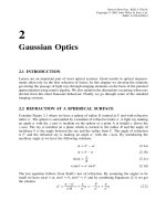
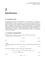
13
Fibre Optics in Metrology
13.1 INTRODUCTION
With a carrier frequency of some 10
14
Hz, light has the potential of being modulated at
much higher frequencies than radio waves. Since the mid-1960s the idea of communication
through optical fibres has developed into a vital branch of electro-optics. Great progress
has been made and this is now an established technique in many communication systems.
From the viewpoint of optical metrology, optical fibres are an attractive alternative for
the guiding of light. An even more important reason for studying optical fibres is their
potential for making new types of sensors.
13.2 LIGHT PROPAGATION THROUGH
OPTICAL FIBRES
More extensive treatments on optical fibres can be found in Senior (1985), Palais (1998),
Keiser (1991) and Yu and Khoo (1990).
Figure 13.1 shows the basic construction of an optical fibre. It consists of a central
cylindrical core with refractive index n
1
, surrounded by a layer of material called the
cladding with a lower refractive index n
2
. In the figure a light ray is incident at the end of
the fibre at an angle θ
0
to the fibre axis. This ray is refracted at an angle θ
1
and incident
at the interface between the core and the cladding at an angle θ
2
. From Snell’s law of
refraction we have
n
0
sin θ
0
= n
1
sin θ
1
(13.1)
where n
0
is the refractive index of the surrounding medium. From the figure, we see that
θ
1
=
π
2
− θ
2
(13.2)
If θ
2
is equal to the critical angle of incidence (cf. Section 9.5), we have
sin θ
2
=
n
2
n
1
(13.3)
Optical Metrology. Kjell J. G
˚
asvik
Copyright
2002 John Wiley & Sons, Ltd.
ISBN: 0-470-84300-4
308
FIBRE OPTICS IN METROLOGY
n
0
q
0
n
2
n
1
q
1
q
2
Lost ray
Cone of
acceptance
Figure 13.1 Basic construction of an optical fibre
which combined with Equations (13.1) and (13.2) gives
θ
0
≡ θ
a
= sin
−1
n
2
1
− n
2
2
n
0
(13.4)
For θ
0
<θ
a
the light will undergo total internal reflection at the interface between the core
and the cladding and propagate along the fibre by multiple reflections at the interface,
ideally with no loss. For θ
0
>θ
a
some of the light will transmit into the cladding and
after a few reflections, most of the light will be lost.
This is the principle of light transmission through an optical fibre. The angle θ
a
is an
important parameter when coupling of the light into a fibre, usually given by its numerical
aperture NA:
NA = n
0
sin θ
a
=
n
2
1
− n
2
2
(13.5)
In practice, coupling of the light into the fiber can be accomplished with the help of a
lens, see Figure 13.2(a) or by putting the fibre in close proximity to the light source and
Laser beam
2q
a
Cladding
Core
(a)
(b)
LED
Cladding
Core
Index matching liquid
Figure 13.2 Coupling of light into a fibre by means of (a) a lens and (b) index-matching liquid
LIGHT PROPAGATION THROUGH OPTICAL FIBRES
309
linking them with an index-matching liquid to reduce reflection losses, Figure 13.2(b).
When using the method in Figure 13.2(a), it is important to have the angle of the incident
cone less than θ
a
to get maximum coupling efficiency.
The above description of light propagation through an optical fibre is not fully complete.
To gain better understanding, the fibre must be treated as a waveguide and the electro-
magnetic nature of the light must be taken into account. If a waveguide consisting of a
transparent layer between two conducting walls is considered, the electric field across the
waveguide will consist of interference patterns between the incident and reflected fields,
or equivalently, between the incident field and its mirror image, see Figure 13.3. The
path-length difference l between these fields is seen from the figure to be
l = d sin θ(13.6)
where d is the waveguide diameter and θ is the angle of the incident beam. From
the boundary conditions for such a waveguide we must have destructive interference
at the walls, i.e. the path-length difference must be equal to an integral number of half
the wavelength:
l = m
λ
2
(13.7)
which gives
sin θ =
mλ
2d
(13.8)
where m is an integer. Thus we see that only certain values of the angle of incidence are
allowed. Each of the allowed beam directions are said to correspond to different modes
of wave propagation in the waveguide. The field distribution across the waveguide for the
lowest-order guided modes in a planar dielectric slab waveguide are shown in Figure 13.4.
This guide is composed of a dielectric core (or slab) sandwiched between dielectric
claddings of lower refractive index. As can be seen, the field is non-zero inside the
Incident
beam
d
sin q
Reflected
beam
Conducting wall
Conducting wall
Mirror image of
reflected beam
Mirror image of
incident beam
q
d
Figure 13.3 A conducting slab waveguide
310
FIBRE OPTICS IN METROLOGY
TE
0
n
2
n
1
TE
2
Cladding
Core
Cladding
TE
1
Figure 13.4 Electric field distribution of the lowest-order guided transversal modes in a dielectric
slab waveguide
cladding. This is not in contradiction with the theory of total internal reflection (see
Section 9.5) which predicts an evanescent wave decaying very rapidly in the cladding
material.
The lowest number of modes propagating through the waveguide occurs when the
angle of incidence is equal to θ
a
. Then (assuming n
0
= 1forair)
sin θ
a
=
mλ
2d
=
n
2
1
− n
2
2
(13.9)
or
d
λ
=
m
2
n
2
1
− n
2
2
(13.10)
To have only the lowest-order mode (m = 0) propagating through the waveguide, we
therefore must have
d
λ
<
1
2
n
2
1
− n
2
2
(13.11)
An exact waveguide theory applied to an optical fibre is quite complicated, but the results
are quite similar. The condition for propagating only the lowest-order mode in an optical
fibre then becomes
d
λ
<
2.405
2π
n
2
1
− n
2
2
=
2.405
2π(NA)
=
0.383
NA
(13.12)
A fibre allowing only the lowest-order mode to propagate is called a single-mode fibre,
in contrast to a multimode fibre which allows several propagating modes.
13.3 ATTENUATION AND DISPERSION
That light will propagate through a fibre by multiple total internal reflections without
loss is an idealization. In reality the light will be attenuated. The main contributions to
attenuation is scattering (proportional to λ
−4
) in the ultraviolet end of the spectrum and
absorption in the infra-red end of the spectrum. Therefore it is only a limited part of
ATTENUATION AND DISPERSION
311
First
window
Total
loss
Rayleigh
scattering
Second
window
OH absorption
peak
Third
window
800 900 1000 1100 1200 1300 1400 1500 1600 1700
0
0.5
1.0
1.5
2.0
2.5
3.0
Wavelength (nm)
Attenuation (dB/km)
Figure 13.5 Attenuation in a silica glass fibre versus wavelength showing the three major wave-
length regions at which fibre systems are most practical. (From Palais, J. C. (1998) Fiber Optic
Communications (4th edn), Prentice Hall, Englewood Cliffs, N.J.) Reproduced by permission of
Prentice Hall Inc.)
the electromagnetic spectrum where fibre systems are practical. Figure 13.5 shows the
attenuation as a function of wavelength for silica glass fibres. Here are also shown the
three major wavelength regions at which fibre systems are practical. These regions are
dictated by the attenuation, but also by the light sources available.
Another source of loss in fibre communication systems is dispersion. Dispersion is due
to the fact that the refractive index is not constant, but depends on the wavelength, i.e.
n = n(λ). In fibre systems one talks about material dispersion and waveguide dispersion.
Here we will briefly mention material dispersion. That the refractive index varies with
wavelength means that a light pulse from a source of finite spectral width will broaden as
it propagates through the fibre due to the different velocities for the different wavelengths.
This effect has significant influence on the information capacity of the fibre. The parameter
describing this effect is the pulse spread per unit length denoted τ/L where τ is the
difference in travel time for two extreme wavelengths of the source’s spectral distribution
through the length L.Thisgives
τ
L
=
1
ν
g
(13.13)
In dispersive media a light pulse propagates at the group velocity (Senior 1985) defined by
ν
g
=
dω
dβ
(13.14)
With the relations
ω = kc =
2πc
λ
(13.15a)
β = kn =
2πn
λ
(13.15b)
312
FIBRE OPTICS IN METROLOGY
we get
1
ν
g
=
dβ
dω
=
dβ
dλ
dλ
dω
=
−λ
2
2πc
2π
1
λ
dn
dλ
−
n
λ
2
=
1
c
n − λ
dn
dλ
(13.16)
This gives
τ
L
=
1
ν
g
=
n − λdn/dλ
c
(13.17)
The pulse spread per unit length per wavelength interval λ becomes
τ
Lλ
=
d
dλ
1
ν
g
=
d
dλ
n
c
−
λ
c
dn
dλ
=−
λ
c
d
2
n
dλ
2
(13.18)
Refractive index
1.45
n
l
0
(a)
0
(b)
d
n
2
/ dl
2
l
0
Wavelength
Wavelength
Figure 13.6 (a) Refractive index versus wavelength for SiO
2
glass and (b) The second derivative
of the curve in (a)
DIFFERENT TYPES OF FIBRES
313
The material dispersion is defined as M = (λ/c)(d
2
n/dλ
2
). The pulse spread per unit
length then can be written as
τ
L
=−Mλ (13.19)
The refractive index for pure silicon dioxide (SiO
2
) glass used in optic fibres has the
wavelength dependence shown in Figure 13.6(a). At a particular wavelength λ
0
,thereis
an inflection point on the curve. Because of this, d
2
n/dλ
2
= 0atλ
0
as seen from the
curve of the second derivative in Figure 13.6(b). For pure silica, the refractive index is
close to 1.45 and the inflection point is near λ
0
= 1.3 µm. Therefore this wavelength is
very suitable for long distance optical fibre communication.
13.4 DIFFERENT TYPES OF FIBRES
Another construction than the step-index (SI) fibre sketched in Figure 13.1 is the so-
called graded-index (GRIN) fibre. It has a core material whose refractive index varies
with distance from the fibre axis. This structure is illustrated in Figure 13.7. As should be
easily realized, the light rays will bend gradually and travel through a GRIN fibre in the
oscillatory fashion sketched in Figure 13.7(d). As opposed to an SI fibre, the numerical
aperture of a GRIN fibre decrease with radial distance from the axis. For this reason, the
coupling efficiency is generally higher for SI fibres than for GRIN fibres, when each has
the same core size and the same fractional refractive index change.
Conventionally, the size of a fibre is denoted by writing its core diameter and then its
cladding diameter (both in micrometers) with a slash between them. Typical dimensions
(a) (b) (c)
(d)
2
a
r
n
2
n
n
1
a
0
r
z
n
(
r
)
n
2
2
a
Figure 13.7 Graded index fibre: (a) refractive index profile; (b) end view; (c) cross-sectional
view; and (d) ray paths along a GRIN fibre