Luận văn tốt nghiệp Tiếng Anh: GRADUATION THESIS CABLESTAYED BRIDGE
Bạn đang xem bản rút gọn của tài liệu. Xem và tải ngay bản đầy đủ của tài liệu tại đây (12.72 MB, 329 trang )
UNIVERSITY OF TRANSPORT AND COMMUNICATIONS
FACULTY OF CIVIL ENGINEERING
DEPARTMENT OF BRIDGE AND TUNNEL
GRADUATION THESIS
CABLE-STAYED BRIDGE
APPROVED BY : DR. TRAN THE TRUYEN
CHECKED BY : PROF.DR. NGUYEN NGOC LONG
PREPARED BY : NGUYEN HOANG LOC
CLASS : ENGLISH BRIDGE AND ROAD – COURSE 46
HA NOI, MAY 2010
PREFACE 2010
preface
In the development of our country today, we need to build more and more
structure to serve the demand of human life. In which, Transport is the important
field that is considered with large investment and concern of society. We need to
get more and more skillful engineer to update the modern technology of the world
and build for us many modern structures with high quality and aesthetic.
After 5 years learnt in the University of Transport and Communications, with
the willing of myself and the whole-heart teaching of my teachers, I have been
grant many experiences with help me in the future.
This graduation thesis is the result of 5 years studied in this university. It is the
summary of my studying process. During making this graduation thesis, I have
been helped by my lecturers in the Department Bridge and Tunnel (UTC) for
finishing my thesis.
During make this graduation thesis, because of the time and my limited
knowledge, so there is no doubt that I will get some mistakes. I hope I can take
advice of our lecturers to make my finished graduation thesis and learn by
experience in the future.
Finally, I absolutely give a thanks to Prof.Dr. Nguyen Ngoc Long and all
lecturers in the Department of Bridge and Tunnel(UTC), and especially, Dr Tran
The Truyen who advise me about what is best to finish my graduation thesis.
Thank you for all!
Ha Noi, May 2010
Nguyen hoang loc
NGUYEN HOANG LOC
Page 4
PREFACE 2010
Comment of guide lecturer
.....................................................................................................................................
.....................................................................................................................................
.....................................................................................................................................
.....................................................................................................................................
.....................................................................................................................................
.....................................................................................................................................
.....................................................................................................................................
.....................................................................................................................................
.....................................................................................................................................
.....................................................................................................................................
.....................................................................................................................................
.....................................................................................................................................
.....................................................................................................................................
.....................................................................................................................................
.....................................................................................................................................
.....................................................................................................................................
.....................................................................................................................................
.....................................................................................................................................
.....................................................................................................................................
.....................................................................................................................................
.....................................................................................................................................
.....................................................................................................................................
.....................................................................................................................................
.....................................................................................................................................
.....................................................................................................................................
.....................................................................................................................................
.....................................................................................................................................
.....................................................................................................................................
.....................................................................................................................................
.....................................................................................................................................
.....................................................................................................................................
.....................................................................................................................................
.....................................................................................................................................
.....................................................................................................................................
.....................................................................................................................................
.....................................................................................................................................
.....................................................................................................................................
.....................................................................................................................................
.....................................................................................................................................
.....................................................................................................................................
NGUYEN HOANG LOC
Page 5
PREFACE 2010
Comment of checked lecturer
.....................................................................................................................................
.....................................................................................................................................
.....................................................................................................................................
.....................................................................................................................................
.....................................................................................................................................
.....................................................................................................................................
.....................................................................................................................................
.....................................................................................................................................
.....................................................................................................................................
.....................................................................................................................................
.....................................................................................................................................
.....................................................................................................................................
.....................................................................................................................................
.....................................................................................................................................
.....................................................................................................................................
.....................................................................................................................................
.....................................................................................................................................
.....................................................................................................................................
.....................................................................................................................................
.....................................................................................................................................
.....................................................................................................................................
.....................................................................................................................................
.....................................................................................................................................
.....................................................................................................................................
.....................................................................................................................................
.....................................................................................................................................
.....................................................................................................................................
.....................................................................................................................................
.....................................................................................................................................
.....................................................................................................................................
.....................................................................................................................................
.....................................................................................................................................
.....................................................................................................................................
.....................................................................................................................................
.....................................................................................................................................
.....................................................................................................................................
.....................................................................................................................................
.....................................................................................................................................
.....................................................................................................................................
NGUYEN HOANG LOC
Page 6
PREFACE 2010
Comment of student
- Đây là nội dung cho các bạn khóa Cầu Đường khác tham khảo. Phần tham khảo
thứ nhất này là phần tơi đã hồn thành từ ngày 25-4-2010.
- Thứ nhất,tôi khuyên các bạn ngành Cầu thuộc các lớp khác ngồi lớp Cầu Đường
Anh có khả năng tiếng anh thì cố gắng phấn đấu làm và bảo vệ đồ án tốt nghiệp
bằng Tiếng Anh. Điều này rất có lợi cho sự thăng tiến và giúp ích cho cơng việc
của các bạn. Các bạn bảo vệ ĐATN bằng Tiếng anh thuộc bất kỳ lớp nào trong
trường giao thông đều được cấp giấy chứng nhận do nhà trường cấp và khơng có gì
khác biệt so với các bạn thuộc lớp Cầu Đường Anh.Nếu các bạn có điều gì cần trao
đổi thì có thể e-mail cho tơi theo địa chỉ :
(Civil Engneer – Mr Loc)
- Thứ hai, ngay từ cuối năm thứ 4 hay càng sớm càng tốt các bạn hãy thực
hành cho mình khả năng sử dụng Excel thật tốt (bao gồm cả VBA) để có thể
lập ra các bảng tính chun nghiệp, giúp cho qua trình làm ĐATN. Ở đây tơi
sẽ nêu một số nội dung chính về công việc chuẩn bị cho làm ĐATN Cầu
Dây Văng.
+ Chuẩn bị bảng tính :
- Móng cọc đài cao
- Kiểm tốn trụ - mố.
- Kiểm tốn tháp cầu.
- Tính duyệt mặt cầu – dầm ngang – tai đeo, dây văng.
- Tính duyệt dầm chủ, lưu ý là dầm đơn năng (TT) hoặc dầm đa năng.
- Bảng tính DCNL Cầu Dây Văng.
- và một số bảng tính quan trọng khác.
+ Chuẩn bị khả năng về phần mềm chuyên ngành.
o Midas/Civil (có thể học phần mềm tại trung tâm của Thầy Vĩnh
(giảng viên Cầu Hầm –ĐHGTVT - 0936922370)
o FB-Pier
o RM2006
o Có thể nghiên cứu them về SAP
o Autocad các bạn tự học.
- Thứ ba, các bạn nên tổ chức thời gian để thực hiện từng phần mà mình đặt ra
theo kế hoạch, như vậy qua trình làm ĐATN sẽ dễ dàng hơn.
- Thứ tư, các câu hỏi khi bảo vệ tiếng anh các bạn e-mail tôi sẽ gửi cho.
- Cuối cùng tôi chúc các bạn thành công, bảo vệ ĐATN bằng Tiếng anh tốt
(Hội đồng bảo vệ có thể gồm: Thầy Hâu, T. Tuấn Bình, Thầy Nhiệm, Thầy
Truyền, Thầy Tiến, Thầy Duy hoặc hơn)
NGUYEN HOANG LOC
Page 7
PREFACE 2010
CONTENTS
chapters
Volume i
CHAPTER I
CHAPTER II
CHAPTER III
CHAPTER IV
VOLUME II
Design contents
page
Design requirement
3
preface
4
Comment of leading lecturer
5
Comment of checking lecturer
6
CONTENTS
7
General introduction
8
Preliminary design OF BRIDGE
ALTERNALTIVES
THE PREMILINARY DESIGN OF THE 1st
ALTERNATIVE
CABLE-STAYED BRIDGE
THE PREMILINARY DESIGN OF THE 2 sd
ALTERNATIVE PRESTRESSED
CONCRETE BRIDGE
the premininary design of the 3rd
alternative
composite bridge
Bridge alternative selection
9
9
45
78
118
121
Chapter vii
TECHNICAL DESIGN
general view of detail design
CABLE-STAYED bidge
Internal force redistribution of
cables
DECK AND TRANSVERSE BEAM
Chapter viii
Abutment calculation
174
Chapter ix
design of bridge pylon
207
Chapter x
Design of bridge beam
CONSTRUCTION PLANNING AND
DESIGN
REFERENCE
243
CHAPTER V
Chapter vi
CHAPTER XI
REFERENCE
NGUYEN HOANG LOC
121
124
145
286
329
Page 8
PREFACE 2010
GENERAL INTRODUCTION
I - Specification for bridge design
- Specification: 22TCN – 272 – 05 Ministry of Transport
-
Design load : HL – 93
II- Structural scale
Permanent bridge with service life > 100 years
III- Navigation clearance
Level i
H = 10 m
B = 80 m
IV- Bridge width
-Traffic lane : 2x4.5m width
- Pedestrain lane : 2x1.5m width
- Design speed V=60km/h
V - Geologic feature
Layer 1 : Clay , 2 m thick
Layer 2 : Sandy soil , 8 m thick
Layer 3 : Alluvial sand , 15 m thick
Layer 4 : Medium sand , unlimited thick
VI - bridge profile
- The top of bridge center curve is circular curve ,R=5000m
- Longitudinal slope : i=3%
NGUYEN HOANG LOC
Page 9
THESIS GRADUATE
DESIGN of CABLE-STAYED BRIDGE
A thesis submitted in partial fulfillment for the degree Engineer of
Engineering
In the
Department of Tunnel and Bridge
Faculty of Civil Engineering
University of Communications and Transport
May 2010
| English Bridge and Road – Course 46
UNIVERSITY OF TRANSPORT AND COMMUNICATIONS
CHAPTER I: THE PREMILINARY DESIGN
OF THE 1st ALTERNATIVE CABLE-STAYED
BRIDGE
2010
NGUYEN HOANG LOC-ENGLISH BRIDGE AND ROAD –C46
CHAPTER I: THE PREMILINARY DESIGN OF THE 1st ALTERNATIVE CABLE- 2010
STAYED BRIDGE
CHAPTER I: THE PREMILINARY DESIGN OF THE 1st ALTERNATIVE
CABLE-STAYED BRIDGE
I - General introduction
- In the trends of industrialization and modernization in Viet Nam,
infrastructure construction is the essential problem. In the other hand, transport
construction, maintenaince and upgrade is important.
- One of the needed requirement for the now-and- the-future bridge is: not
only satisfy the need of modern transportation but also has an economic, easthetical
bridge to make a symbol of Viet Nam in the future.
- In the past, when designing the bridge, the designer often used the steel
bridge, concrete bridge and prestress concrete bridge…with the simple or
continuous span. These types of bridge are just economic with the small and
medium length.
- Therefore, we need to design a bridge with longer span, simple
construction and has an easthetical shape.
- Researching some developed and developing country, we can see that, with
the span of 50 150m, the prestress concrete bridge which is erected with the
cantilever method has highly effective. The maximum span from this type of bridge
is 240m ( Hamana Bridge, Japan). However, the limited economical span of this
type is just only 200m.
- The cable-stayed bridge is the non-deformed structure, so it can ensure the
good rigidity. The system works like a girder is placed on elastic bearings (cable).
The increase of elastic bearing not only doesn’ t make the increasement of cable
mass and the compression in the girder, but also make the reduction of flexural
moment in the girder., especially when it subjected to the dead load. Therefore, the
cable-stayed bridge can spread larger span length when the mass is increased
neglectable
- Moreover, in the development history of bridge, the cable-stayed bridge has
had a large concern of the researchers, designers and architects. From the time the
first cable-stayed bridge built at Stralsund, Sweden, in 1955, the cable-stayed
bridges are built all over the world
- One favorite basic characteristic of this type of bridge is the diversity. The
bridge can has different span length, cable plane or cable layout. The shape and the
height of the pylon are also the beautiful characteristic
NGUYEN HOANG LOC
Page 10
CHAPTER I: THE PREMILINARY DESIGN OF THE 1st ALTERNATIVE CABLE- 2010
STAYED BRIDGE
- The cable-stayed bridge with the advantages of bearing capacity,
reasonably erection technology, and diversity are one of the important building of
many country.
- In Viet Nam, the first cable-stayed bridge was built in 1976 at Dakrong
(Quang Tri) but by the end of February in 1999 this bridge was collapsed, and then
until 2000, this bridge is fixed with reinforce concrete. Another cable-stayed
bridges are My Thuan Bridge (Tien Giang - Vinh Long) in 1998 - 2001 , Han river
Bridge (Da Nang), Bai Chay Bridge, Can Tho Bridge….
II - general description
II.1 - design specifications
- The specification : 22TCN - 272 - 05 of the Ministry of Transport
II.2 - Structural layout
- Span length: 132.5+276+132.5
- The height of pylon : 75.2 m from the pylon bot.
- The cross-section has constraint height with the shape TT .
- The length of one panel 10m .
- Number of cables on one pylon: 4x13=52 cables.
- Cross beams are placed at the entired length of girders, with the spacing 5m
III - Span calculation
III.1 – Selection of the span plot
The cable-stayed bridge can has one, two or three spans , in which the theespans cable-stayed bridge is popular. It has many advantages of structure, bearing
capacity as well as construction technology.
Studying the characteristics of geology-geometry-topography-hydrology and
surrounding architecture, the conditions of zone’ s economy-society-politics, I
decide to choose the cable-stayed bridge alternative with two cable plane
symmetric to the pylon.
Span division 132.5+276+132.5 m.
With these analyses above, we can choose:
- Segment length d=10 m.
- Closing segment dg= 0,78d ≈ 8 m
- Length of segments near pylon dt= 1,4d = 14 m
NGUYEN HOANG LOC
Page 11
CHAPTER I: THE PREMILINARY DESIGN OF THE 1st ALTERNATIVE CABLE- 2010
STAYED BRIDGE
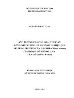
III.2 - The shape and the height of main girder
Each of the girder has advantages and disadvantages. According to the
accretion trends, the use of any section base on ensuring the bearing capacity and
having the simplest construction technology, which suitable with erection capacity
and.
Therefore, I decide to use the cross-section of girder similar with the cross-section
in My Thuan Bridge (erected). The My Thuan Bridge has 3 spans with length 150
+350 +150m, the cross-section has 2 main girder with the shape of two-meters
trapezium, 25 centimeters slab thickNess and 5.2 meters cross beam spacing.
Cables is anchored at the cross beam which placed outside the girder.
According to bridge statistics in the world and in Viet Nam, the ratio of
girder height and length is
h
1
1
=
.
100
300
l
So on, I choose the cross-section of main girder with the shape TT as shown in the
figure below:
13700
4500
1000
600
400
1200
10000
1000
100
250
1800
2%
160
600
1200
160
1447
1800
250
450 100
398
400
250
2%
1500 500750
450
4500
750500 1500
III.3 - Choosing the additional devices for the cable-stayed
bridge
Nowadays, single strands are used popularly in the pre-stress concrete and cablestayed bridge because they are easy to transport, install and suitable with the
anchor.
I use the single strand type with 7 wires 5 (diameter of 15,2 mm). In
addition, I use the strands which can reduce the expansion of strand ( due to the
displacement caused by self weight when subjected to live load).
The strands are pretension separately and assembled into group in the anchor
block. The work of installing the cable is very simple because the cable is installed
with strand one by one and no form traveler is needed.
NGUYEN HOANG LOC
Page 12
CHAPTER I: THE PREMILINARY DESIGN OF THE 1st ALTERNATIVE CABLE- 2010
STAYED BRIDGE
The anchor block is the cylinder steel block which has bored to placed the
strands and strands are clamped by the 3 segments cotter.
Using the 7 fiber strands cable and clamp anchor is the premium alternative.
III.4 - The shape and cross-section of pylon
- Pylon height is chose to satisfy some requirements:
+) Ensure the connection between cables and pylon.
+) Ensure the inclined angle of cables is suitable for bearing capacity
demand:
Inclined angle of mid cable is a = 22.5 25 o
- From these analysis, I choose the pylon has some typical parameters such as:
+) Total pylon height h th = 72.5 m
+) Height from the cap to beam bottom hct= 15 m
+) Height from beam bottom to nearest cable h tt = 37.155m
+) Height of cable spacing : hdv =18 m
+) Height from the top anchor to the pylon top hdt = 2.5m
- The table of calculating inclined angle of cable:
cable
1
2
3
4
5
6
7
8
9
10
11
12
13
a - cables angle at side span
x
h
14
37.4094
24
38.9094
34
40.4094
44
41.9094
54
43.4094
64
44.9094
74
46.4094
84
47.9094
94
49.4094
104
50.9094
114
52.4094
124
53.9094
132.5
55.4094
NGUYEN HOANG LOC
angle(degree)
69.48
58.33
49.92
43.61
38.79
35.06
32.09
29.70
27.73
26.08
24.69
23.50
22.69
Page 13
CHAPTER I: THE PREMILINARY DESIGN OF THE 1st ALTERNATIVE CABLE- 2010
STAYED BRIDGE
b - cables angle at mid span
cable
x
h
1'
14
37.4094
2'
24
38.9094
3'
34
40.4094
4'
44
41.9094
5'
54
43.4094
6'
64
44.9094
7'
74
46.4094
8'
84
47.9094
9'
94
49.4094
10'
104
50.9094
11'
114
52.4094
12'
124
53.9094
13'
132.5
55.4094
III.5 - Force calculation
angle
69.48
58.33
49.92
43.61
38.79
35.06
32.09
29.70
27.73
26.08
24.69
23.50
22.69
III.5.1 - Calculation of the dead load
1- Dead load in stage I
- Dead load in stage I including:
+) Main girder self weight: DCdc
+) Weight of cross beam: DCdn
+) Weight of tail : DCtd
DCITC = DCdc+ DCdn+ DCtd
Main girder self weight: DCdc
Name
Symbol
Value
Unit
Height of T beam
H
180
cm
Width of the deck
Bcau
1450
cm
Width of the wings
bc
1200
cm
ThickNess of the slap
bs
100
cm
ThickNess of the web
hc
25
cm
NGUYEN HOANG LOC
Page 14
CHAPTER I: THE PREMILINARY DESIGN OF THE 1st ALTERNATIVE CABLE- 2010
STAYED BRIDGE
ThickNess of transferred wings
hc'
26.50
cm
Area of real beam cross section
A
72800
cm2
Weight of the beam
DCdc
165.57
KN/m
Name
Symbol
Value
Unit
Collar beam height
hdn
164.7
cm
Collar beam depth
ddn
30
cm
Collar beam length
Ldn
1000
cm
Weight of collar beam
Pdn
24.24
kN/m
Number of the collar beam
ndn
111
beams
Distance between collar beams
adn
500
cm
Height of lug ear
htd
110
cm
ThickNess of lug ear
dtd
109.4
cm
Length of lug ear
Ltd
150
cm
Distances between lug ears
atd
100
cm
Number of lug ears
ntd
104
ears
Weight of lug ear
Ptd
8.28
kN/m
- Standard dead load in stage I
Name
Symbol
Value unit
Standard dead load in stage 1
DCtc
gtc1
198.0
kN/m
6
Calculation ofd dead load at stage 1
DCtt
gtt1
257.5
kN/m
8
2 - Dead load in stage II
- Dead load in stage II including:
+) Weight of barrier
NGUYEN HOANG LOC
Page 15
CHAPTER I: THE PREMILINARY DESIGN OF THE 1st ALTERNATIVE CABLE- 2010
STAYED BRIDGE
+) Weight of hand railing
+) Weight of wearing surface
DWIITC = DWclc+ DWlc+tv+ DWws
- Calculation of the weight of wearing surface
No
Layers
ThickNess (m)
ga (kN/m3)
P (kN/m2)
1
Asphalts layer
0.070
23
1.61
2
Covering layer
0.000
24
0.00
3
Moistening proof layer 0.004
15
0.06
4
Cross fall layer
0.000
24
0.00
0.074
Total
1.67
- Pedestrian covering layer weight
• Pedestrian width :
ble = 3
m
qle = 5.01
kN/m
Bxe= 9
m
• Weight
qle = P.ble
- Pavement covering layer weight
• Pavement width:
• Weight
qxe = 15.03 kN/m
qxe = P.Bxe
- Weight of banisters and handrail
qch =
0.1 kN/m
-Railings weight
NGUYEN HOANG LOC
Page 16
CHAPTER I: THE PREMILINARY DESIGN OF THE 1st ALTERNATIVE CABLE- 2010
STAYED BRIDGE
+ Width
blcc
=
0.50
m
+ Height
hlcc
=
0.67
m
gc
=
24
kN/m3
qclcc
=
12.06
kN/m
+ Weight
qclcc = 2.blcc.hlcc.gc.0,75
- Calculation of the dead load in stage II
+) Standard dead load
DWIITC = qclcc+ qch+ qle+xe =32.2 kN/m
+) Calculation ofd dead load
DWIItt = g . DWIITC = 1,5x32.2 = 48.3 KN/m
3 - Summary the dead load in two stages
name
Value
Unit
Standard dead load at stage 1
DCtc
198.06 kN/m
Standard dead load at stage 2
DWtc 32.2
kN/m
Calculation ofd load at stage 1
DC
17.84
kN/m
Calculation ofd load at stage 2
DCtt
247.58 kN/m
Calculation ofd load at stage 2
DWtt 48.3
Total load
DW
kN/m
295.88 kN/m
III.5.2 - Calculation of the live load
1 - The live load according to the specifications 22TCN - 272 - 05
- The live load HL 93 follows the specifications 22TCN - 272 - 05 . Depend onf the
shape of the influence line, we have to placed live load to get the maximum load
effect.
+) Load modifier : hi = 1
+) Load factor : gi = 1,75
NGUYEN HOANG LOC
Page 17
CHAPTER I: THE PREMILINARY DESIGN OF THE 1st ALTERNATIVE CABLE- 2010
STAYED BRIDGE
+) Impact factor 1+IM/100 = 1+25/100 = 1,25
2 - Calculation of the load distribution factor
- Steps to Calculation of the load distribution factor
+) Consider the slab is the cantilever beam placed in the rigid bearing (main
girder).
+) Draw the bearing reaction influence line.
+) Place the unfavorable load according to the transversal direction
+) Determind the Y-value of influence line.
+) Calculation of the load distribution factor:
1
gi . Yi
2
- We can see the table
Truck
Tandem
Lans
pedestrian
y1
0.555
0.555
0.091
-0.045
y2
0.718
0.718
0.500
0.091
y3
0.827
0.827
0.500
0.909
y4
0.991
0.991
0.909
1.045
g
1.546
1.546
1
1
NGUYEN HOANG LOC
Page 18
CHAPTER I: THE PREMILINARY DESIGN OF THE 1st ALTERNATIVE CABLE- 2010
STAYED BRIDGE
III.6 - Calculating the force and choose cable crosssection
III.6.1 - Determining the cable
- Using the seven-wire stranded cables of the VSL company with the parameters as
follows:
+) The nominal diameter: 15,2 mm
+) The yield strength : fpy = 1670 Mpa
+) The ultimate strength : fpu = 1860 Mpa
+) Using strength : f = b.fpu
b = 0,45 with the major load combination
b = 0,5 with the additional load combination
b = 0,56 with the erection load combination
=> The using strength of cable with the major load combination is:
fsa = 0,45.1860.102 = 837 Mpa
III.6.2 - Calculting the cable internal force
1 - Calculating the cable internal force due to dead load in stage I
a- Formulas
- The cable internal force in stage I is Calculation ofd with the erection stage
layout. The formula is:
I
Si
gtt .d
Sin i
+) Internal force in the cable i
+) Internal force in mid cable
Sg
gtt I .d g
2.Sin g
b- Cable internal force table due to dead load in stage I
NGUYEN HOANG LOC
Page 19
CHAPTER I: THE PREMILINARY DESIGN OF THE 1st ALTERNATIVE CABLE- 2010
STAYED BRIDGE
Side span of the T1
Number
ai
Sinai
Si
(kN)
1
2
3
4
5
6
7
8
9
10
11
12
13
69.48
58.33
49.92
43.61
38.79
35.06
32.09
29.70
27.73
26.08
24.69
23.50
22.69
0.937
0.851
0.765
0.690
0.627
0.574
0.531
0.495
0.465
0.440
0.418
0.399
0.386
2643.45
2908.85
3235.52
3589.64
3951.50
4310.16
4659.72
4997.17
5321.10
5631.04
5927.06
6209.52
6417.07
Main span of the T1
Number
ai
1'
69.48
2'
58.33
3'
49.92
4'
43.61
5'
38.79
6'
35.06
7'
32.09
8'
29.70
9'
27.73
10'
26.08
11'
24.69
12'
23.50
13'
22.69
So, we select premilinary cables with:
Sinai
Si (kN)
0.937
0.851
0.765
0.690
0.627
0.574
0.531
0.495
0.465
0.440
0.418
0.399
0.386
2643.45
2908.85
3235.52
3589.64
3951.50
4310.16
4659.72
4997.17
5321.10
5631.04
5927.06
6209.52
6417.07
- With the side span
NGUYEN HOANG LOC
Page 20
CHAPTER I: THE PREMILINARY DESIGN OF THE 1st ALTERNATIVE CABLE- 2010
STAYED BRIDGE
Cable i
Si
(kN)
Ai
Ai
Essential
Cable
Selection (selected
(essential) wires for
diameter
wires
wires)
2
(cm )
1 side
(m)
(m2)
1
2643.45
31.58
2
2908.85
34.75
3
3235.52
38.66
4
3589.64
42.89
5
3951.50
47.21
6
4310.16
51.50
7
4659.72
55.67
8
4997.17
59.70
9
5321.10
63.57
10
5631.04
67.28
11
5927.06
70.81
12
6209.52
74.19
13
6417.07
76.67
- With the midle span
Cable i
Si
(kN)
1
2
3
4
5
6
7
8
9
10
11
12
13
2643.45
2908.85
3235.52
3589.64
3951.50
4310.16
4659.72
4997.17
5321.10
5631.04
5927.06
6209.52
6417.07
11
12
14
15
17
18
20
21
23
24
25
26
27
35
35
35
35
45
45
45
50
50
50
60
60
60
0.00494
0.00494
0.00494
0.00494
0.00635
0.00635
0.00635
0.00705
0.00705
0.00705
0.00846
0.00846
0.00846
0.08
0.08
0.08
0.08
0.09
0.09
0.09
0.09
0.09
0.09
0.10
0.10
0.10
Ai
Ai
Essential
Cable
Selection (selected
(essential) wires for
diameter
wires
wires)
(cm2)
1 side
(m)
(m2)
31.58
34.75
38.66
42.89
47.21
51.50
55.67
59.70
63.57
67.28
70.81
74.19
76.67
NGUYEN HOANG LOC
11
12
14
15
17
18
20
21
23
24
25
26
27
35
35
35
35
45
45
45
50
50
50
60
60
60
0.00494
0.00494
0.00494
0.00494
0.00635
0.00635
0.00635
0.00705
0.00705
0.00705
0.00846
0.00846
0.00846
0.08
0.08
0.08
0.08
0.09
0.09
0.09
0.09
0.09
0.09
0.10
0.10
0.10
Page 21
CHAPTER I: THE PREMILINARY DESIGN OF THE 1st ALTERNATIVE CABLE- 2010
STAYED BRIDGE
2 - Calculation of the cable internal force due to dead load in stage II and live load
a-Formulas
- The cable internal forces due to dead load in stage II and live load are Calculation
ofd with the final layout in the service stage.
- To Calculation of the internal force, I use the programme Midas 7.01 for drawing
the influence line, then placed load in the influence line
- Internal force due to dead load in stage II
SttII = qttII .
- Internal force due to live load
+) Due to lane load: SLantt = glan. qlan . v+
+) Due to pedestrian load: SNGtt = gNG. qNG . v+
+) Due to HL93: Placed one truck into the influence line at the most
unfavorable position(the axle spacing can vary from 4,3 - 9 m )
PttXT = gxt . m.IM. P.i yi
+) Due to tandem: Placed one tandem into the influence line at the most
unfavorable position
Ptt2T = gxt . m.IM. P.i yi
b- Table of Internal force influence line in cable
(III.6.2.1.b)
c - Table of cable internal force due to dead load in stage II and live load
A - With the side span
II
Cable i
Sin¸i
Si (kN)
1
2
3
4
5
6
7
8
9
10
11
12
0.937
0.851
0.765
0.690
0.627
0.574
0.531
0.495
0.465
0.440
0.418
0.399
81.8
156.4
199.6
220.4
295.6
303.0
306.4
338.1
329.5
313.9
350.6
320.8
NGUYEN HOANG LOC
Truck
364.3
460.4
493.8
504.8
642.1
632.5
600.2
614.8
578.0
527.7
660.3
879.2
Sh (kN)
Tandem
309.2
392.4
423.7
436.6
558.5
551.1
521.8
535.0
511.4
482.1
611.0
808.3
People
45.1
59.2
67.4
74.0
101.4
103.6
98.6
102.1
99.3
108.0
158.2
212.2
Shmax
(kN)
409.4
519.6
561.2
578.8
743.5
736.1
698.8
716.9
677.3
635.7
818.5
1091.4
Page 22
CHAPTER I: THE PREMILINARY DESIGN OF THE 1st ALTERNATIVE CABLE- 2010
STAYED BRIDGE
13
0.386
297.0
1104.9
1015.6
266.2
1371.1
B - With the midle span
Cable i
Sin∝i
SiII (kN)
1'
0.937
82.8
2'
0.851
156.1
3'
0.765
198.3
4'
0.690
219.3
5'
0.627
296.3
6'
0.574
308.0
7'
0.531
317.4
8'
0.495
358.3
9'
0.465
357.6
10'
0.440
348.0
11'
0.418
393.3
12'
0.399
356.8
13'
0.386
308.3
3 - Summary of cable internal force
Truck
366.1
460.0
484.1
488.3
617.5
614.3
605.9
652.6
639.3
624.1
727.3
723.7
751.3
Sh (kN)
Tandem
311
392.2
414.5
421.1
535.6
535.0
528.7
570.5
562.4
554.5
653.6
656.5
685.8
People
45.4
59.3
65.5
89.5
93.9
97.2
98.4
108.6
108.6
110.1
139.1
149.5
164.0
Shmax
(kN)
411.5
519.3
549.6
577.8
711.4
711.5
704.3
761.2
747.9
734.2
866.4
873.2
915.3
Side span
Number
1
2
3
4
5
6
7
8
9
10
11
12
13
SI
(kN)
2643.45
2908.85
3235.52
3589.64
3951.50
4310.16
4659.72
4997.17
5321.10
5631.04
5927.06
6209.52
6417.07
NGUYEN HOANG LOC
S II
(kN)
Smax
(kN)
Stotal
(kN)
81.8
156.4
199.6
220.4
295.6
303.0
306.4
338.1
329.5
313.9
350.6
320.8
297.0
409.4
519.6
561.2
578.8
743.5
736.1
698.8
716.9
677.3
635.7
818.5
1091.4
1371.1
3134.65
3584.85
3996.32
4388.84
4990.6
5349.26
5664.92
6052.17
6327.9
6580.64
7096.16
7621.72
8085.17
Page 23
CHAPTER I: THE PREMILINARY DESIGN OF THE 1st ALTERNATIVE CABLE- 2010
STAYED BRIDGE
Mid span
Number
SI
(kN)
SII
(kN)
Smax
(kN)
Stotal
(kN)
1'
82.8
411.5
2643.45
2'
156.1
519.3
2908.85
3'
198.3
549.6
3235.52
4'
3589.64
219.3
577.8
5'
296.3
711.4
3951.50
6'
308.0
711.5
4310.16
7'
317.4
704.3
4659.72
8'
358.3
761.2
4997.17
9'
357.6
747.9
5321.10
10'
5631.04
348.0
734.2
11'
5927.06
393.3
866.4
12'
356.8
873.2
6209.52
13'
308.3
915.3
6417.07
III.6.3 - Choosing the cross-section of cable
- We can use the formula
A
3137.75
3584.25
3983.42
4386.74
4959.2
5329.66
5681.42
6116.67
6426.6
6713.24
7186.76
7439.52
7640.67
S
ful
In which :
+) S : The reaction due to dead load and live load in cables with the
equivalent factors following the specififcations.
+) ful : Calculation ofd strength of cable material, ful = 837 (MPa)
These above formula base on the condition of using the whole capacity of the cable
. From that, the cross-section of cables are different. However, in design
calculation, if the differences are little, we can choose the cross-section of some
cables similarly, or due to any purpose in design procedure, we can increase or
decrease some cables cross-section.
- Table of choosing the cable cross-seciton
Side span
Number
1
SI (total)
max (kN)
Ai
(cm2)
3134.65
31.58
NGUYEN HOANG LOC
Essential wires
Selection wires
n for 1 side
13
35
Ai
(m2)
0.00494
Page 24
CHAPTER I: THE PREMILINARY DESIGN OF THE 1st ALTERNATIVE CABLE- 2010
STAYED BRIDGE
2
3
4
5
6
7
8
9
10
11
12
13
3584.85
3996.32
4388.84
4990.6
5349.26
5664.92
6052.17
6327.9
6580.64
7096.16
7621.72
8085.17
34.75
38.66
42.89
47.21
51.50
55.67
59.70
63.57
67.28
70.81
74.19
76.67
Number
Si (total)
max (kN)
Ai
(m2)
15
17
19
21
23
24
26
27
28
30
32
34
Mid span
Essential wires
n
35
35
35
45
45
45
50
50
50
60
60
60
0.00494
0.00494
0.00494
0.00635
0.00635
0.00635
0.00705
0.00705
0.00705
0.00846
0.00846
0.00846
Selection wires
Ai
(m2)
1'
3137.75
0.003749
13
0.00494
35
2'
3584.25
0.004282
15
0.00494
35
3'
3983.42
0.004759
17
0.00494
35
4'
4386.74
0.005241
19
0.00494
35
5'
4959.2
0.005925
21
0.00635
45
6'
5329.66
0.006368
23
0.00635
45
7'
5681.42
0.006788
24
0.00635
45
8'
6116.67
0.007308
26
0.00705
50
9'
6426.6
0.007678
27
0.00705
50
10'
6713.24
0.008021
28
0.00705
50
11'
7186.76
0.008586
30
0.00846
60
12'
7439.52
0.008888
32
0.00846
60
13'
7640.67
0.009129
32
0.00846
60
III.6.4 - The good work condition of cable
- To ensure the good work of cable in the process of subjecting the load, the cabel
must satisfy some conditions:
+) Ensure the condition of strength
+) Ensure the condition of rigidity: the cable must be checked according to
the allowable defomed condition
- The deflection of cable i due to live load is Determination of by using the
formula:
Yi
1
lo .Soh
li .Sih
``
2
E Ao . cos o .tg i Ai . cos i .sin i
NGUYEN HOANG LOC
Page 25