Tài liệu Flex Cam pptx
Bạn đang xem bản rút gọn của tài liệu. Xem và tải ngay bản đầy đủ của tài liệu tại đây (2.8 MB, 84 trang )
Flex Cam
Hydraulic cylinders and tool slides
for tool and mould-making and
machinery construction
09/2006
2·14175· 2005·2
°
Product No. 2.2901.02.1205.01000
2·14176·2000·1
°
002_14112 29.08.2006 14:54 Uhr Seite 3
Contents
2·1417·2000·1
°
subject to alterations
3
Page
Introduction 5–6
Description 6–7
Stroke rate/Capacity and output 8
Funktion 9
Power Unit/Cam Unit combinations 10
Selecting the components 11–14
Dimensions and Order No 15–45
Cam Units
Force Cylinders
15–40–60–90–150 kN 16–22–30–36–42
Compact Cams
15–40–60–90–150 kN 18–24–32–38–43/1
Power Units
15–40–60–90–150 kN 20–28–34–40–44
Flange Cam 26–27
Electric hydraulic pump 46
Accessories 47–64
Connecting hoses 48
Threaded couplings 49–51
Quick-release couplings 52–53
Charging and control fitting 54
Oil filling unit 55
Assembly tool 56
Control fittings 57
Compound threaded joints 58
Test hoses and couplings
Pressure switches 59–60
Sensor mounting kit 61
Inductive proximity switch/
Connection cable 62
Top mounting for Flange Cam 63
Safety module 64
Safety label 65
Typical installations for monitoring
process safety 67–71
Monitoring 68–71
Typical applications 73–77
FIBRO – The latest technology –
with a tradition of service 78–79
003_14113 29.08.2006 14:57 Uhr Seite 2
2·14178·2000·1
°
subject to alterations
4
General Instructions
System safety, reliability and functionality can be ensured by supplying FIBRO with the application data
and drawings of the installation arrangements for checking.
Please note that the number of the threaded connections and the hose lengths for installation in the
system must be determined.
Assembly, commissioning, maintenance and servicing of the Flex Cam system require
special knowledge and may only be carried out by FIBRO trained, specialist personnel.
You can order the work to be carried out by a FIBRO customer service engineer, to be invoiced in
accordance with our installation tariff.
Just contact us to schedule it for you.
We shall be pleased to answer any technical queries you may have, now or at any time in the future.
As the Flex Cam system which are specially made, we recommend that you keep
reserve systems in stock to avoid the risk of delay when the need arises.
004_14114 29.08.2006 14:58 Uhr Seite 3
2018. Flex Cam
2·14179·2000·1
°
subject to alterations
5
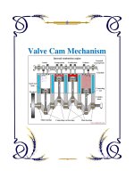
Power Unit
Cam Unit
Accumulator Power Cylinder
Oil charge connectionBurst guard
Nitrogen charge
connection
Nitrogen charge
Piston
Adapter plate
Piston rod guide, sealing
(nitrogen spring)
Limit of stroke
(external)
Duplex piston
(sealing nitrogen
and oil charges)
Piston rod
Bleeding screw
Safety hose
Force Cylinder
Nitrogen charge
Stroke
Nitrogen
charge
connection
Piston
Oil
Hydraulic hose
connection
Hydraulic hose
Hydraulic hose
connection
Flex Cam 2018.
2·14180·2000·1
°
subject to alterations
6
Introduction
The hydraulic cam system is the ideal com-
ponent for executing linear motions at any
point in the available space.
The system is increasingly being used in
tool making, in particular, to drive drawing,
moulding, cutting and drilling operations
where conventional slides cannot be used
due to lack of space or inconvenient
position.
The working motion is generated by the
cam unit (e.g. the working cylinder), which
can be installed in any position in the
available space.
The cam unit is controlled by a driving
cylinder which, in turn, is activated by the
stroke motion of a press, for example.
The link between the two is provided by a
hydraulic hose in which the volume of oil in
the power unit is displaced to the cam unit.
Description
Power Unit
The Power Unit consists of the following components:
• Power Cylinder
• Accumulator
• Adapter plate
The Power Cylinder is filled with oil at one end, while
the machine that executes the stroke is at the opposite
end.
The accumulator is charged with nitrogen gas at one end.
In the idle state, the base of the piston rests on the
accumulator, relieving the pressure on the system.
The adapter plate connects the Power Cylinder to the
Accumulator and Force Cylinder.
In the standard version, the capacity of the accumulator
is matched to the total displacement volume of the
Power Cylinder. It is thus of the same height as the
piston rod. The integral rupture protection device opens
at 517 bar.
The Power Unit is also available with a separate Power
Cylinder and Accumulator.
Cam Units
There are 3 types of Cam Units:
• Force Cylinder 2018.30./40./50./60.
• Compact Cam 2018.11.
• Flange Cam 2018.12.
Force Cylinder 2018.30./40./50./60.
Design
The accumulator is charged with nitrogen gas at one end
(20 – 40 bar). The volume of oil displaced from the Power
Unit acts on the other end when the Power Unit is pres-
surised. The Force Cylinder then extends. The retraction
motion is generated by the nitrogen gas when the pres-
sure is relieved on the stroke side of the Power Cylinder.
The displacement length of the Force Cylinder is twice
as long as the permissible nominal displacement length.
The unused displacement capacity is needed as a com-
partment for the pressurised nitrogen gas in order to
return the stroke.
Applications
The Force Cylinder is designed to drive an individual tool
component (e.g. a slide).
The nominal stroke of the Force Cylinder must be limited
by external stops. The Force Cylinder is not guided and
therefore cannot absorb any side loads. The tool compo-
nents themselves must be guided.
Side loads acting on the Force Cylinder lead to
system failure.
When attaching accessories, be careful to ensure that
the axes are lined up correctly to avoid transverse forces
during the stroke. Coupling pins or similar accessories
must be used for the connection as there must be no
rigid connection between the piston of the Force Cylinder
and the tool components.
006_14116 29.08.2006 14:59 Uhr Seite 3
2018. Flex Cam
2·14187·2000·1
°
subject to alterations
7
Compact Cam 2018.11.
Design
The Power Cylinder starts the piston rod of the Compact Cam
moving when pressurised. The slide is returned by external gas
springs. Two pillars with guideways prevent the tool holder
plate rotating. The clearance in the guides is 0.01 – 0.03 mm.
Applications
The Compact Cam is suitable for hole punching operations
involving no transverse forces. The Compact Cam is gui-
ded and has an internal stop. Punches can be mounted
directly on the tool holder plate.
Side loads on the Compact Cam will lead to
system failure.
In cutting operations with a small cutting clearance and
asymmetrical cutting forces a guide bolster should be provi-
ded, with an external guide to absorb the lateral forces. As
with the Force Cylinder, coupling pins must be used for the
connection between the slide and the external guide
(uncoupling). The Compact Cam is attached by 4 fixing scr-
ews. A feather key groove absorbs the cutting forces. It is
positioned by means of two pilot holes.
Flange Cam 2018.12.
Design
The Flange Cam construction is the same as the construc-
tion of the Compact Cam. The Power Cylinder starts the
piston rod of the Flange Cam moving when pressurised. The
slide is returned by external gas springs. Two pillars with
guideways prevent the tool holder plate rotating. The clea-
rance in the guides is 0.01 – 0.03 mm. The tool holder plate
is supported by a roller and a support plate to absorb lateral
forces.
Applications
The Flange Cam is suitable for work operations with lateral
forces (e.g. bend up, sliding). The Compact Cam is guided
with an integrated stop. Punches can be mounted directly
on the tool holder plate.
A guide bolster with external guide should be pro-
vided for bending operations with asymmetrical
forces.
The Flange Cam is attached by 4 fixing screws. A feather
key groove absorbs the bending forces. It is positioned by
means of two pilot holes.
Alternative drive
For operating the Cam Unit electrically powered Hydraulic
pump units can be used (see page 46). The max. working
pressure must not exceed 150 bar. The max. speeds listed
on page 8 must not be exceeded.
Charging fittings
Nitrogen gas: The Accumulator and Cam Unit can be char-
ged with the gas spring filling charge 2480.00.32.21.
Hydraulic system: The system is filled and vented using
the oil filling unit 2018.00.30.
Filling and venting of the system is described in detail in
the user manual supplied with the system.
Hydraulic connection
See also pages 48-53
User-friendly, flexible high-pressure hoses are ideal for the
hydraulic connections (see page 48).
A space-saving alternative is to use system hydraulic
pipes.
The same screwed couplings are used for both hoses and
pipes.
The hose length should not exceed 2000 mm. This is
important to ensure a constant build-up of pressure and –
even more importantly – to minimise impact during cutting
without a significant pressure build-up.
The couplings should be designed for at least 300 bar
nominal pressure and 1000 bar rupture pressure.
This is essential if the connection is to be sufficiently rigid
and for the rupture protection device to operate at 517 bar.
Quick-release couplings for hydraulic
hoses
We recommend that you use quick-release couplings to
join the hydraulic hoses.
Benefits:
• The system can be filled and vented under optimum con-
ditions when off the tool, either at FIBRO or on site.
• If the tool has to be assembled or dismantled, the
hydraulic hose connecting the Power Unit and the Cam
Unit is disconnected using the quick-release coupling.
It is thus not necessary to dismantle the hoses, drain and
refill the oil and vent the system, which keeps costs
down.
For layout purposes, the dimensions of the commonly
used threaded couplings and hoses are shown on pages 48
to 53.
Leaks and oil level display
The experience we have gained in manufacturing gas
springs enables us to select the most suitable seals.
The result is an effective and long-lasting seal.
The connecting line can be assembled with no leaks, using
available materials and with careful installation.
If an oil leak does occur, it will be compensated short term
by the overtravel volume in the Accumulator.
The Accumulator and Power Cylinder are of the same
height, so any loss of oil from the system will be manife-
sted by a difference in height.
Flex Cam
2·14188·2000·1
°
subject to alterations
8
Stroke rate
The stroke rate is dependent on the minimum flow
opening, the volume of oil and the working and return
pressures. The connecting openings allow a working
stroke rate of up to 0.8 m/s. Although this is limited by
the extent to which the system heats up due to the
high stroke rates. The system temperature should not
exceed 60 °C.
Safety instructions
If the layout of the system gives the Force Cylinder an
excessive displacement volume due to excess over-
travel and/or seizing of the cylinder, the pressure in the
system can exceed the admissible value of 280 bar. In
critical situations, this effect will be counteracted by
the opening of a rupture valve at 517 bar.
The couplings are designed for a nominal pressure of
300 bar and 1000 bar rupture pressure.
On the gas side, the Accumulator is pressurised at 150
bar and is subject to Pressure Equipment Directive
97/23/EC.
To monitor safety during the process, we recommend
installing a control fitting as an additional check on the
gas side - see range of accessories.
Capacity and output
The forces listed in table 1 below are applicable for the
following nitrogen gas pressures:
Accumulator 150 bar
Force Cylinder 20 bar
Compact Cam
2018.11.01500.. and 2018.11.04000.
Gas spring 2480.21. and .23.00000. 180 bar
2018.11.06000.
Gas spring 2487.12.00350. 180 bar
Compact Cam
2018.11.09000.
Gas spring 2480.12.00500. 150 bar
2018.11.15000.
Gas spring 2487.12.00750. 150 bar
Flange Cam
2018.12.04000.049
Gas spring 2480.21. and .23.00000. 180 bar
Comments
The Accumulator and the Force Cylinder are pressure
vessels and as such are subject to the Pressure Equip-
ment Directive 97/23/EC.
During cutting and hole punching operations the nomi-
nal force of the Compact Cam should only be utilised
up to 75% to minimise impact during cutting which is
reinforced by the Accumulator. Impact during cutting
can be reduced by polished tool edges (e.g. roof
shape) and so downtime can be reduced.
Values other than those specified in the above table
may be accepted under certain circumstances or if
different stroke lengths, speeds and frequencies are
combined.
2018.30. 2018.11. 2018.12. 2018.20.
15 40 60 90 150 15 40 60 90 150 40 15 40 60 90 150
25813212 4710154 –––––
10 125 105 125 50
40 180 150 180 180
25, 50, 100 24, 49, 99* 49 35**, 60**, 110**, 160**
(1)
0,8 0,8 0,8 0,8
0,8 0,8 0,8 0,8
30 60 30 60 60 60 30 30
10–40 10–40 10-40 10–40
Flange
Description Force Cylinders Compact Cams Cams Power Unit
Force (magnitude) kN
Initial restoring force kN
Minimum gas pressure bar
Maximum gas pressure bar
Stroke length mm
Maximum speed m/s
Maximum restoring speed m/s
Maximum frequency Strokes/min.
Ambient temperature °C
* not for 2018.11.01500.
** including +10 mm overtravel
1)
not for 2018.20.01500. and 2018.20.15000.
Table 1: Technical data
008_14124 29.08.2006 15:11 Uhr Seite 3
2·14181·2000·1
°
subject to alterations
9
2018. Flex Cam
Function
The individual components of the Flex Cam system
described above interact as follows:
ቢ
The Power Cylinder is actuated by the stroke of the
press.
ባ
Once the pressure build-up in the Flex Cam
exceeds the preset pressure in the Force Cylinder, the
Force Cylinder extends.
ቤ
When the Force Cylinder reaches its working
position, the pressure in the system rises to match the
pressure in the Accumulator. The rest of the displaced
volume of oil is then held in the Accumulator (Power
Cylinder overtravels by approx. 3 - 10 mm).
ብ
This overtravel is essential since it ensures that a
constant contact pressure is built up during each stroke.
At the same time the pressure on the Power Cylinder
is relieved (return travel of the press), the Force
Cylinder is reset by the nitrogen gas.
Pressure ratios in the system
The above diagram shows the oil pressure build-up
during the work cycle. Before the working motion, the
oil-system is pressureless. When the Power Cylinder is
actuated, the oil pressure rises to the preset gas pres-
sure in the Cam Unit. As the Force Cylinder continues to
travel, the volume of gas is further compressed until the
work operation is executed. At the same time, the back-
pressure in the system rises due to the punching
operation, for example. Once the operation has ended,
the Power Cylinder continues as far as the end position
of the Force Cylinder. This ensures that the excess
volume of oil is fully absorbed by the Accumulator. At
the same time, the oil pressure rises to match the
charging pressure in the Accumulator.
If a malfunction occurs in the tool part during system
travel and blocks the travel of the Cam Unit, all the
displaced oil is held in the Accumulator. The oil pressure
increases until it equals that of the compressed nitro-
gen in the Accumulator.
The system is protected by an integral rupture protec-
tion device in the Accumulator which opens at 517 bar
to vent the nitrogen. The resulting system security
protects the tool from damage by the Flex Cam.
12
17
22
160
140
120
100
80
180
60
40
20
0
27
32
37
42
47
52
57
58
53
48
43
38
33
28
23
18
13
2
70
8
3
0
Normal
working stroke
Blocking
slide
P
Accumulator
P
Work
+ P
Retract
P
Retract
Travel [mm]
Oil pressure [bar]
2
3
4
1
P
Oil
= 0
P
Oil
= P
Work
+ P
Retract
P
Oil
= P
Accum.
P
Oil
= P
Accum. +
P
Retract
009_14117 29.08.2006 15:12 Uhr Seite 2
Flex Cam 2018.
2·14182·2000·1
°
subject to alterations
10
Possible combinations
Power Unit with Cam Unit
Cam Unit leading
If a stroke of the Cam Unit is required before the tool
actually reaches its working position, this can be
achieved by incorporating a gas spring. The press stro-
ke actuates a gas spring which, in turn, actuates the
Power Unit, since its prestressing force is higher than
the nominal force of the Power Unit.
When the Cam Unit reaches its end position, the drive
(press) overtravel is compensated by the retracting
piston rod of the gas spring. A spring contact washer
transmits the pressure of the gas spring to the suppor-
ting tube when the Power Unit reaches its end position.
Several Cam Units driven asynchronously
Several Cam Units can be driven by a common Power
Unit. The individual Cam Units should not, however, be
mechanically connected to one another since the
feedrates cannot be totally synchronised due to the
different connection lengths (system losses) and
restoring forces.
Several Cam Units driven synchronously
Synchronous operation can be achieved by using two
systems of the same dimensions, although this appli-
cation requires the restoring force of the individual
Cam Units to be equal, as well.
°
Power
Unit
Press
Cam Unit
°
°
One or more Cam Units driven with delay
A time delay, and thus a variable working sequence for
the Cam Units, can be achieved by combining two
different strokes. The first Power Unit to be actuated
executes the first step. As the Cam Unit moves beyond
its end position, the excess oil is displaced into the
Accumulator (not shown in the diagram). The second
Power Unit can then enter the working sequence as
required.
Variable speed / force drive
The forces or travel speeds can be combined as
required by varying the ratio between Power Unit sizes
and Cam Unit sizes. The maximum travelling speed
should not exceed 0.8 m/s, however.
°
°
Press
Press
Cam Unit
Cam Unit
Power
Unit
Power
Unit
Press
Cam Unit
Press
Cam Unit
Power
Unit
Power
Unit
Slide
°
Gas spring
Spring contact washer
Power
Cylinder
Press
Cam Unit
Supporting
tube
„leading“
010_14118 30.08.2006 10:57 Uhr Seite 3
2018. Flex Cam
2·14183·2000·1
°
subject to alterations
11
Step 3: Order number of the Cam Unit
Select the Cam Unit according to the type of
operation to be performed. See also pages 8,10-12
Compact Cam: 2018.11. .
Flange Cam: 2018.12.04000.049
Force Cylinder: 2018.30. .
Example: The order number for the Compact Cam is
2018.11.04000.049
Transmission ratios in use
Transmission or reduction ratios can be expressed in
four different ways:
a) Force
b) Speeds of the individual Cam Units
c) Press travel speed to Cam Unit travel speed
d) Stroke lengths
Transmission ratios
The nominal transmission ratio of 1:1 is normally used
throughout the system.
The ratio can vary, however, according to the combi-
nation (and number) of Power Units and Cam Units
used (see table on page 10).
Selecting the components
The component sizes are explained step by step
below with regard to the forces required, stroke length
and the number of operations.
Step 1: Size of the Cam Unit
Calculate the force required for the operation to be
carried out. The Cam Unit used should provide suffi-
cient force to execute the operation. If the force requi-
red cannot be precisely calculated, we recommend
that you use a larger Cam Unit.
Force required (kN) Cam Unit
0– 15 2018. .01500.
15– 40 2018. .04000.
40– 60 2018. .06000.
60– 90 2018. .09000.
90–150 2018. .15000.
Force required:
kN Cam Unit size:
Example: If the force required is 22 kN, then a 40 kN Cam Unit
should be used. Cam Unit 2018. .04000.
Step 2: Cam Unit stroke length
Determine the Cam Unit stroke required to execute the
operation in the tool. Use the Cam Unit with the shor-
test possible stroke, but remember that the tool must
have sufficient space for the workpiece.
Required stroke Max. stroke length
length (mm) of Cam Unit (mm) Part number
0– 25 25 (24)*** 2018. . .025*
25– 50 50 (49)*** 2018. . .050*
50–100 100 (99)**
/
*** 2018. . .100*
*) 2018.11. .024/049/099
**) This stroke length does not apply to Compact Cam
2018.11.01500.
***) Compact cam
Stroke length of Cam Unit: mm
Example: If the stroke length required is 35 mm, use a Cam Unit
with a stroke length of 50 mm.
011_14119 29.08.2006 15:13 Uhr Seite 2
Flex Cam 2018.
2·14184·2000·1
°
subject to alterations
12
Step 4a
Size and stroke of the Power Unit
Follow step 4a if one to three Cam Units of the same
size are connected to a given Power Unit. If different
Cam Units are connected to a Power Unit, then step
4b should be used.
Select the Power Unit from the following table. The
table should be read in the following order: Cam Unit –
force – stroke – number – Power Unit – stroke length.
We recommend that no more than three Cam Units be
connected to a single Power Unit.
Make sure that you do not exceed the maximum Cam
Unit stroke speed (0.8 m/s).
Force Stroke Number
Stroke
used
04000 50 2 ?
Cam Unit Power Unit
Selection flowchart
Power Unit = Nominal working force / nominal stroke + 10 mm
overtravel
SU = Working stroke (stroke actually used) + 10 mm
TR = Transmission ratio
Power unit selection table
Cam Unit Nom. Power Unit
force (kN)
stroke (mm)
No. 15 kN SU TR 40 kN SU TR 60 kN SU TR 90 kN SU TR 150 kN SU TR
15 25 1 035 35 1,0 035 20 2,5 035 16 4,0 035 14 6,3 035 13 9,8
25 2 060 60 0,5 035 30 1,2 035 23 2,0 035 18 3,1 035 15 4,9
25 3 110 85 0,3 060 40 0,8 035 29 1,3 035 22 2,1 035 18 3,3
50 1 060 60 1,0 035 30 2,5 035 23 4,0 035 18 6,3 035 15 9,8
50 2 110 110 0,5 060 50 1,2 035 35 2,0 035 26 3,1 035 20 4,9
50 3 110 70 0,8 060 48 1,3 035 34 2,1 035 25 3,3
100 1 110 110 1,0 060 50 2,5 035 35 4,0 035 26 6,3 035 20 9,8
100 2 110 91 1,2 060 60 2,0 060 42 3,1 035 30 4,9
100 3 160 131 0,8 110 85 1,3 060 58 2,1 060 41 3,3
40 25 1 110 72 0,4 035 35 1,0 035 26 1,6 035 20 2,5 035 16 3,9
25 2 060 60 0,5 060 41 0,8 035 30 1,3 035 23 2,0
25 3 110 85 0,3 060 57 0,5 060 40 0,8 035 29 1,3
50 1 060 60 1,0 060 41 1,6 035 30 2,5 035 23 3,9
50 2 110 110 0,5 110 72 0,8 060 50 1,3 035 35 2,0
50 3 160 160 0,3 110 103 0,5 110 70 0,8 060 48 1,3
100 1 110 110 1,0 110 72 1,6 060 50 2,5 035 35 3,9
100 2 160 134 0,8 110 89 1,3 060 61 2,0
100 3 160 129 0,8 110 86 1,3
60 25 1 110 110 0,3 60 50 0,6 035 35 1,0 035 26 1,6 035 20 2,4
25 2 110 91 0,3 060 60 0,5 060 42 0,8 035 30 1,2
25 3 160 131 0,2 110 85 0,3 060 58 0,5 060 41 0,8
50 1 110 91 0,6 060 60 1,0 060 42 1,6 035 30 2,4
50 2 110 110 0,5 110 74 0,8 060 51 1,2
50 3 160 160 0,3 110 106 0,5 110 71 0,8
100 1 110 110 1,0 110 74 1,6 060 51 2,4
100 2 160 138 0,8 110 92 1,2
90 25 1 110 73 0,4 060 49 0,6 035 35 1,0 035 26 1,6
25 2 160 136 0,2 110 88 0,3 060 60 0,5 060 42 0,8
25 3 160 127 0,2 110 85 0,3 060 58 0,5
50 1 160 136 0,4 110 88 0,6 060 60 1,0 060 42 1,6
50 2 110 110 0,5 110 74 0,8
50 3 160 160 0,3 110 106 0,5
100 1 110 110 1,0 110 74 1,6
150 25 1 110 108 0,3 110 71 0,4 060 49 0,6 035 35 1,0
25 2 160 132 0,2 110 88 0,3 060 60 0,5
25 3 160 127 0,2 110 85 0,3
50 1 160 132 0,4 110 88 0,6 060 60 1,0
50 2 110 110 0,5
100 1 110 110 1,0
012_14120 30.08.2006 10:58 Uhr Seite 3
2018. Flex Cam
2·14185·2000·1
°
subject to alterations
13
See also the following examples:
Example 1 (Fig. 1): A Power Unit 2018.20.04000.060
is provided as standard for a Compact Cam
2018.11.04000.049. The nominal stroke of the Power
Unit is 60 mm. The transmission ratio is 1:1. The stroke
of the Compact Cam is thus performed at the same
speed as the press.
Example 2 (Fig. 2): If a press stroke of just 30 mm
can be used to execute the operation, then a larger
Power Unit 2018.20.09000.035 should be used for the
Cam Unit 2018.11.04000.049. The Power Unit stroke
used is 30 mm, the transmission ratio is 2.5. If the
press speed is 0.3 m/s, then the Cam Unit stroke
speed obtained is 2.5 × 0.3 m/s = 0.75 m/s.
The stroke used by Power Unit and Cam Unit can be
perfectly matched to any special constraints associa-
ted with the tool.
For some applications, the speed of the Cam Unit
must be increased in proportion to the press speed.
If several Cam Units are connected to a
Power Unit, then the individual Cam Units
will not have the same stroke speed.
Fig. 1: Selection for example 1
Fig. 2: Selection for example 2
04000 50 1 60
Cam Unit
Power Unit
2018.20.
04000.060
04000 50 1 30
Cam Unit
Power Unit
2018.20.
09000.035
Example 3 (Fig. 3): A Power Unit 2018.20.04000.110
can be used with two Compact Cams
2018.11.04000.049 and a useful press stroke of
110 mm. The Power Unit stroke used is 110 mm and
the transmission ratio is 0.5.
If the press speed is 0.3 m/s, then the mean Cam Unit
stroke speed obtained is 0.5 × 0.3 = 0.15 m/s.
Order number of the Power Unit.
See also pages 19, 23, 27, 31, 35.
Fig. 3: Selection for example 3
04000 50 2 110
Cam Unit
Power Unit
2018.20.
04000.110
Power Unit:
2018.20. .
013_14121 30.08.2006 10:58 Uhr Seite 2
Flex Cam
2·14186·2000·1
°
subject to alterations
14
Step 4b
Size and stroke of the Power Unit
for different Cam Unit sizes
The total volume of oil in the Cam Units should be cal-
culated using the following formula. The total volume
of oil is the sum of all the volumes for all Cam Units.
The volume is the product of the piston surfaces and
strokes used. The total volume of oil V
N
for the Power
Units corresponds to the minimum volume of oil for the
Cam Units (in dm
3
). A
N
is the piston surface area in the
Cam Unit (dm
2
) as shown in table 2.
V
N
= [(A
1
и s
1
) + (A
2
и s
2
) ...(A
N
и s
N
)] : 100 (Formula 1)
A
N
= Piston surface area of Cam Units
s
N
= Stroke length of Cam Units
The volume of oil of the selected Power Unit should
be greater than 0,189 dm
3.
For example, the
2018.20.06000.060 supplies 0,251 dm
3
.
(The 2018.20.04000.110 could also be used)
(see table 3)
Calculate the used stroke of the Power Unit:
s
Gerf
= ((V
N
: V
G
) и s
G
)+ 10
s
Gerf
= ((0,189 : 0,251) и 50) + 10 (see formula 2)
s
Gerf
= 48 mm
In the above example, we recommend a Power Unit
2018.20.06000.060 with a used stroke of 48 mm. The
admissible Cam Unit stroke speeds defined in section
9 must not be exceeded. It should also be noted that
the Cam Units will have different stroke speeds if two
Cam Units are driven by a single Power Unit.
Example:
Select a Power Unit to operate a Compact Cam
2018.11.01500.049 and a Force Cylinder
2018.30.04000.050 with a used working stroke of just
40 mm.
V
N
= [(A
WK
и s
WK
) + (A
AZ
и s
AZ
)] : 100
V
N
= [(0,13 и 49) + (0,31 и 40)] : 100 (see formula 1)
V
N
= 0,189
Select the appropriate Power Unit from Table 3.
The Power Unit must supply the minimum volume of
oil as calculated above. Calculate the required Power
Unit stroke s
Gerf
using the following formula:
s
Gerf
= [(V
N
:V
G
) и s
G
] + 10 (Formula 2)
V
N
=Total volume of oil of Cam Units
V
G
=Total volume of oil of Power Unit
s
G
= Power Unit stroke
s
Gerf
= Power Unit stroke required
Total volume of oil of Cam Units: V
N
= dm
3
Power Unit stroke used: s
Gerf
= mm
WK AZ AK 15 kN 40 kN 60 kN 90 kN 150 kN
A
N
(dm
2
) 0,13 0,31 0,50 0,79 1,23
Tab. 2: Piston surface area of Cam Units
Stroke Nominal Power Unit size 2018.20.
length stroke length s
G
15 kN 40 kN 60 kN 90 kN 150 kN
.035 25 0,031 0,078 0,126 0,196 0,307
.060 50 0,063 0,156 0,251 0,393 0,614
.110 100 0,126 0,312 0,502 0,785 1,227
.160 150 0,188 0,468 0,753 1,178 1,841
Tab. 3: Volume of oil of Power Unit V
G
(dm
3
)
WK = Compact Cam 2018.11. .
AZ = Force Cylinder 2018.30. .
AK = Flange Cams 2018.12. .
Step 5
Select appropriate hoses and screwed couplings. The
maximum admissible hose length between Power Unit
and the Cam Unit is 2000 mm. The nominal hose dia-
meter is determined on the basis of the size of the
Power Unit. The hose size is matched to the flow of oil
(see page 48).
➭
It is easiest to determine the correct hose
length if both Power Unit and Cam Unit are
installed inside the tool.
Remember to protect the hose against sharp edges
etc. The hose moves slightly during operation due to
the pulsating oil pressure.
Observe the minimum bending radius.
Depending on the press speed a nominal hose width
smaller than the standard nominal width may be used
(see table 4).
Nominal hose size Press speed
Standard nominal
width Max. speed
Power Unit 0,8 m/s 0,6 m/s 0,4 m/s 0,2 m/s
2018.20.01500 DN 12 DN 12 DN 12 DN 12
2018.20.04000 DN 20 DN 20 DN 12 DN 12
2018.20.06000 DN 25 DN 20 DN 20 DN 12
2018.20.09000 DN 25 DN 25 DN 20 DN 12
2018.20.15000 DN 32 DN 32 DN 25 DN 20
Table 4: Press speed/nominal hose size
014_14122 30.08.2006 10:59 Uhr Seite 3
2·14189·2000·1
°
15
Dimensions and Order No.
Cam Units
Force Cylinders
Compact Cam
Flange Cam
Power Units
Flex Cam
015_14125 29.08.2006 15:15 Uhr Seite 2
Force Cylinder 15 kN 2018. .01500.
A
P
P
R
O
V
E
D
9
7
/
2
3
/
E
C
ø11
ø4
12
ø9
34,5
43
2222
33
+0,1
10
65
±0,1
4
l
min
58
13
a
5311
89*
70
13
ø25
56,5
56,5
70
13
3)
ø95
17
M6
31
19
31
l
min
1
/
2
G
+0,2
10
12,5
3
81,5
58
26*
ø50,2
±0,1
ø25
8
R2
+0,2
70
38
3
b
2018.30.01500.
2018.50.01500.
2018.60.01500.
2480.055.00750
2480.057.00750
2018.40.01500.
16
2·14190·2000·1
°
subject to alterations
16
* +4,5 mm with sealing stopper
1)
Nitrogen gas connector: caution – before
removing the connector check that the
cylinder has no gas pressure.
2)
Stroke length: Important – the nominal
stroke length must be maintained from
the very start by means of an external
stop.
The unused residual stroke is required as
a compression chamber for the nitrogen
gas, if the gas pressure will increase and
may cause damage.
3)
This fastening may only be subjected to
pressure (by support).
2018. .01500.025 25 173 214 192 1,5 3,1
2018. .01500.050 50 223 264 242 1,5 3,1
2018. .01500.100 100 323 364 342 1,5 3,1
* isothermic
2018. .01500.
2018. .01500.
Restoring force in kN*
at 20 bar
Force Cylinder (max. 40 bar)
Order no Stroke l
min
abStroke start Stroke end
On the piston rod
2480.045.00750
On the hydraulic
connector
2480.046.00750
Stroke
Stroke
Stroke
Stroke
2)
Torsion protection groove
Spare parts
Mounting flanges
Spare parts
Mounting flanges
Hydraulic connection G
1
/
2
Hydraulic
connection G
1
/
2
Rating plate
Bleeder valve
Nitrogen gas
connection
1)
Stroke
Stroke
2)
016_14126 30.08.2006 10:59 Uhr Seite 3
2·14191·2000·1
°
subject to alterations
17
017_14127 29.08.2006 15:16 Uhr Seite 2
2·14192·2001· 2
°
subject to alterations
18
Compact Cam 15 kN 2018.11.01500.
ø40
11
ø7,5
21
±0,015
44
±0,015
7,5
52
7
12
20
44
29
l
1
+0,02
ø8
14
+0,02
12
22
(2x)
l
6,5
44
33
e
ø11(2x)
73
82
7,5
26,5
42
ø20
59
56
1)
Max.
stroke
Locating pin л8 (2x)
Hydraulic connection
G
1
/
2
Venting M10x1
M8 fixing screw (4x)
2018.11.01500.
2018.11.01500.
2018.11.01500.024 24 94 155,5 133,5 2 2,6
049 49 119 180,5 158,5 2 2,6
Restoring force in kN
Compact Cam Max. at 180 bar
Order No stroke e l l
1
Stroke start Stroke end
Note:
1)
The punch should preferably be mounted
in the middle of the piston rod.
It can also be located in the shaded area
if necessary.
A guide bolster with external guide to
absorb the lateral forces should be
provided for coping and cutting
operations.
A
P
P
R
O
V
E
D
9
7
/
2
3
/
E
C
018_14128 30.08.2006 11:00 Uhr Seite 3
44
ø40
1)
28,5
19,5
25
20
±0,015
7,5
l
1
+0,02
ø8
14
+0,02
12
22
(2x)
l
52
7
12
11
ø7,5
21
29
l
2
±0,015
44
ø20
59
56
ø11(2x)
73
82
7,5
26,5
6,5
33
e
44
42
2·16267·2005·2
°
subject to alterations
19
Compact Cam 15 kN
2018.11.01500. .1 with gas monitoring connection
2018.11.01500. .1
Install together with measuring hose and control fitting (gas spring and nitrogen connection are valveless).
2018.11.01500. .1
2018.11.01500.024.1 24 94 155,5 133,5 107 2 2,6
2018.11.01500.049.1 49 119 180,5 158,5 132 2 2,6
Restoring force in kN
Compact Cam max. at 180 bar
Order No stroke e l l
1
l
2
Stroke start Stroke end
Note:
1)
The punch should preferably be mounted
in the middle of the piston rod.
It can also be located in the shaded area
if necessary.
A guide bolster with external guide to
absorb the lateral forces should be
provided for coping and cutting
operations.
A
P
P
R
O
V
E
D
9
7
/
2
3
/
E
C
Max.
stroke
Locating pin л8 (2x)
Hydraulic connection
G
1
/
2
Venting M10x1
M8 fixing screw (4x)
Nitrogen gas connection
G
1
/
8
019_16266 06.09.2006 10:15 Uhr Seite 2
* Tighten M8 fixing screw to 25 Nm
Power Unit 15 kN
with separate Accumulator 2018.25.01500.
2·16272·2001·1
°
subject to alterations
20
42
84
24
30
2
l
1
l
ø50,1
50
30
l
ø32
ø50,1
3
40
20
80
90
130
ø9 (x2)
60
110
ø11 (x4)
50
80
80
50
2018.25.01500.
Power Cylinder
Nitrogen gas
connection G
1
/
8
Fixing screw
Accumulator
Nominal hose size G
1
/
2
Rupture protection
device
Hydraulic filling opening G
1
/
4
Hydraulic connection
JIC
1,5
/
16
"
-12
Hydraulic connection G
1
/
2
Stroke
1)
2018.25.01500.
2018.
25
.01500.035 35 220 201 130
2018.
20
.01500.060 60 270 251 180
2018.
20
.01500.110 110 370 351 280
Power Unit stroke
Order No +10
1)
ll
1
l
2
1)
The overtravel compensation is the nominal stroke + 10 mm additional stroke.
A
P
P
R
O
V
E
D
9
7
/
2
3
/
E
C
020_16271 06.09.2006 10:15 Uhr Seite 3
ø11
30
3
c
l
50
80
50
80
130
160
ø32
2018.20.01500.
2018.
20
.01500.035 185 220 35
2018.
20
.01500.060 210 270 60
2018.
20
.01500.110 260 370 110
Power Unit Stroke
Order No. c l +10
1)
2·14193·2001·2
°
subject to alterations
21
1)
The overtravel compensation is the nominal stroke + 10 mm additional stroke.
2018.20.01500. Power Unit 15 kN
2018.20.01500.
A
P
P
R
O
V
E
D
9
7
/
2
3
/
E
C
Power Cylinder
Nitrogen gas connection G
1
/
8
Rating plate
Accumulator
Adapter plate
M12 for lifter stud
(2x)
Rupture protection device
Hydraulic filling opening G
1
/
4
Hydraulic connection G
1
/
2
Stroke
1)
021_14129 30.08.2006 11:01 Uhr Seite 2
Force Cylinder 40 kN 2018. .04000.
A
P
P
R
O
V
E
D
9
7
/
2
3
/
E
C
15 ø13
ø11
16
b
2628
64
37
90
68
120,5*
101
57
ø36
19
56
a
43,5
73,5
90
73,5
3)
ø122
M8
20
8
30
19
3
68
31
R2,5
ø36
3
/
4
G
+0,2
10
2018.30.04000.
2018.50.04000.
2018.60.04000.
2480.055.01500
2480.057.01500
2018.40.04000.
l
min
15,5
26*
ø75,2
±0,1
+0,2
ø4
92,5
16
90
10
19
3
l
min
+0,1
10
4
±0,1
Stroke
Stroke
Stroke
Stroke
Stroke
2)
Stroke
2)
Torsion protection groove
Spare parts
Mounting flanges
Spare parts
Mounting flanges
On the piston rod
2480.045.01500
On the hydraulic
connector
2480.046.01500
Hydraulic connection G
3
/
4
Hydraulic
connection G
3
/
4
Rating plate
Bleeder valve
Nitrogen gas
connection
1)
* +4,5 mm with sealing stopper
1)
Nitrogen gas connector: caution – before
removing the connector check that the
cylinder has no gas pressure.
2)
Stroke length: Important – the nominal
stroke length must be maintained from the
very start by means of an external stop.
The unused residual stroke is required as a
compression chamber for the nitrogen
gas, if the gas pressure will increase and
may cause damage.
3)
This fastening may only be subjected to
pressure (by support).
2018. .04000.025 25 195 246 219 4,2 8,4
2018. .04000.050 50 245 296 269 4,2 8,4
2018. .04000.100 100 345 396 369 4,2 8,4
* isothermic
2018. .04000.
Restoring force in kN*
at 20 bar
Force Cylinder (max. 40 bar)
Order no Stroke l
min
abStroke start Stroke end
2·14194·2000·1
°
subject to alterations
22
°
2018. .04000.
022_14130 29.08.2006 15:18 Uhr Seite 3
2·14195·2001·2
°
subject to alterations
23
023_14131 30.08.2006 11:01 Uhr Seite 2
Compact Cam 40 kN 2018.11.04000.
A
P
P
R
O
V
E
D
9
7
/
2
3
/
E
C
Note:
1)
The punch should preferably be mounted
in the middle of the piston rod.
It can also be located in the shaded area
if necessary.
A guide bolster with external guide to
absorb the lateral forces should be
provided for coping and cutting
operations.
ø60
1)
11
ø7,5
37
ø26
16
±0,015
8
+0,02
(2x)
25
71
12
7
ø10
+0,02
20
l
1
l
27
63
41
74
8
e
44
41
105
97,5
ø15(2x)
9,5
38,5
74
±0,015
74
92
95
2·14196·2000·0
°
24
2018.11.04000.
2018.11.04000.
2018.11.04000.024 24 135 214 187 4 5,2
049 49 160 239 212 4 5,4
099 99 210 289 262 4 5,6
subject to alterations
Restoring force in kN
Compact Cam Max. at 180 bar
Order No stroke e l l
1
Stroke start Stroke end
Max.
stroke
Locating pin л10 (2x)
Hydraulic connection
G
3
/
4
Venting M10x1
M10 fixing screw (4x)
024_14132 30.08.2006 11:02 Uhr Seite 3
2018.11.04000. .1
2018.11.04000.024.1 24 135 214 187 112 4 5,2
2018.11.04000.049.1 49 160 239 212 162 4 5,2
2018.11.04000.099.1 99 210 289 262 237 4 5,2
ø60
1)
56,5
28,5
41
l
2
25
71
12
7
16
±0,015
8
+0,02
(2x)ø10
+0,02
20
l
1
l
27
11
ø7,5
37
41
25
74
8
e
44
ø26
±0,015
74
92
95
9,5
38,5
105
97,5
ø15(2x)
74
63
2·16277·2001·1
°
subject to alterations
25
Compact Cam 40 kN
2018.11.04000. .1 with gas monitoring connection
2018.11.04000. .1
Restoring force in kN
Compact Cam max. at 180 bar
Order No stroke e l l
1
l
2
Stroke start Stroke end
Note:
1)
The punch should preferably be mounted
in the middle of the piston rod.
It can also be located in the shaded area if
necessary.
A guide bolster with external guide to
absorb the lateral forces should be
provided for coping and cutting operations.
Install together with measuring hose and control fitting (gas spring and nitrogen connection are valveless).
Duplicate nitrogen gas ports for connecting the measuring hose.
Use only one port whilst keeping the other one closed.
A
P
P
R
O
V
E
D
9
7
/
2
3
/
E
C
Max.
stroke
Locating pin л10 (2x)
Hydraulic connection
G
3
/
4
Venting M10x1
M10 fixing screw (4x)
Nitrogen gas connection
G
1
/
8
Additional nitrogen gas
port G
1
/
8
025_16276 29.08.2006 15:20 Uhr Seite 2