Tài liệu Valve Cam Mechanism docx
Bạn đang xem bản rút gọn của tài liệu. Xem và tải ngay bản đầy đủ của tài liệu tại đây (2.04 MB, 53 trang )
Valve Cam Mechanism
1
ME-430 INTRODUCTION TO COMPUTER AIDED DESIGN
Valve Cam Mechanism
Pro/ENGINEER Wildfire 3.0
Dr. Herli Surjanhata
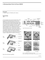
There are 6 parts that will be used in this mechanism analysis:
• shaft_mount.prt — the ground body.
• camshaft.prt (rotating body)
• rocker.prt (oscillating body)
2
• valve_guide.prt (ground body)
• valve.prt (sliding body)
• rocker_shaft.prt (rotating body)
PART: SHAFT_MOUNT.PRT
3
PART: CAMSHAFT.PRT
4
PART: ROCKER.PRT
PART: ROCKER_SHAFT.PRT
5
PART: VALVE.PRT
6
PART: VALVE_GUIDE.PRT
7
CREATE AN ASSEMBLY – rocker_arm.asm
Create a new assembly called
rocker_arm.
Uncheck Use default
template.
The New File Options dialog
box appears.
8
Select System of Units of
mmns_asm_design.
Under Parameters, fill
DESCRIPTION and
MODEL BY with Rocker
Arm Assembly and your
name.
OK.
The assembly should
have default datum
planes – ASM_FRONT,
ASM_RIGHT, and
ASM_TOP.
9
Click to open rocker_shaft.prt
Select
to assemble the
rocker_shaft.prt
at default
location.
Click
to finish the assembly operation.
Click
and open rocker.prt,
Keep default setup for
assembly.
Apply the following constraints between rocker_shaft and rocker – see below.
• Align the axis of the rocker.prt with the axis of the of rocker_shaft.prt
Align constraint.
• Align OFFSET the FRONT datum plane of the rocker.prt with the
ASM_FRONT datum plane of the rocker_arm.asm assembly Align
constraint. The offset distance is 25 mm.
10
The result of the assembly is shown below.
Save the assembly. The rocker_arm.asm will be sub-assembly for total
valve_cam assembly.
11
CREATE AN ASSEMBLY – valve_cam.asm
Create a new assembly called
valve_cam.
Uncheck Use default
template.
The New File Options dialog
box appears.
12
Select System of Units of
mmns_asm_design.
Under Parameters, fill
DESCRIPTION and
MODEL BY with Valve
Cam Mechanism and
your name.
OK.
The assembly should
have default datum
planes – ASM_FRONT,
ASM_RIGHT, and
ASM_TOP.
13
Bring in the part
shaft_mount.prt
and select
to
assemble the
shaft_mount.prt
at default
location.
Click
to complete the
assembly.
In order to install rocker_arm.asm and valve_guide.prt datum planes will be
created.
First create a datum plane that is 25 mm offset from ASM_FRONT.
Select Datum Plane Tool
.
Pick ASM_FRONT datum plane.
14
Click OK and ADTM1 is created.
15
Create a new datum plane through the axis of top hole of the shaft_mount. This
datum plane should be parallel with ASM_TOP.
16
Create a datum plane through the axis of the top hole and make a 20° angle with
ADTM2 – see figure below.
17
Create a datum plane through the axis of the top hole and normal with ADTM3 –
see figure below.
18
Create a datum plane that is - 52 mm offset with ADTM3 – see figure below.
19
Create a datum plane that is - 31 mm offset with ADTM4 – see figure below.
20
Click to create an axis through intersection between ADTM6 and ADTM1 –
see figure below.
Create a pin connection between rocker arm and shaft mount.
Click
, and open rocker_arm.asm.
From the list,
select Pin for
creating a pin
connection.
21
Apply the following constraints in creating pin connection between rocker arm and
shaft mount– see figure below:
• Align the axis A_2 rocker_shaft of the rocker_arm.asm with the axis A_3
of the top hole of shaft_mount.prt as Axis alignment constraint.
• Align the ASM_FRONT datum plane of the rocker_arm.asm with the
FRONT datum plane of the shaft_mount.prt as Translation constraint.
Pick and pick the rocker_shaft.
Drag-rotate the rocker shaft.
22
Create a pin connection for the camshaft and shaft_mount.
Open camshaft.prt in the assembly.
From the list, select Pin for creating a
pin connection.
Apply the following constraints for pin connection between camshaft and
shaft_mount – see below.
• Align the axis A_5 of the camshaft.prt with the axis A_4 of the bottom hole
of shaft_mount.prt as Axis alignment constraint.
• Align the FRONT datum plane of the camshaft.prt with the ADTM1 datum
plane of the valve_cam.asm assembly as Translation constraint.
23
Pick and pick the camshaft.
Try to rotate the camshaft about the shaft_mount.
Open valve_guide.prt and assemble the valve_guide to the assembly with the
following constraints:
• Align the TOP datum plane of the valve_guide.prt with the inclined
ADTM5 datum plane of the assembly.
24
• Align the axis A_2 of the valve_guide.prt with the axis AA_1 created at
the intersection between ADTM1 and ADTM6.
Create a slider connection for the valve and valve_guide.
Open valve.prt in the assembly.