Tài liệu Cutting Tools P4 pptx
Bạn đang xem bản rút gọn của tài liệu. Xem và tải ngay bản đầy đủ của tài liệu tại đây (656.99 KB, 9 trang )
Cutting
Tool
Applications
Cutting Tool Applications
By George Schneider, Jr. CMfgE
2
Tooling & Production/Chapter 4
www.toolingandproduction.com
4.1 Introduction
Turning is a metal cutting process used for the generation of cylindrical surfaces.
Normally the workpiece is rotated on a spindle and the tool is fed into it radially, axially,
or both ways simultaneously, to give the required surface. The term ‘turning’, in the gen-
eral sense, refers to the generation of any cylindrical surface with a single point tool.
More specifically it is often applied just to the generation of external cylindrical surfaces
oriented primarily parallel to the workpiece axis. The generation of surfaces oriented pri-
marily perpendicular to the workpiece axis are called ‘facing’. In turning the direction of
the feeding motion is predominantly axial with respect to the machine spindle. In facing
a radial feed is dominant. Tapered and contoured surfaces require both modes of tool feed
at the same time often referred to as ‘profiling’.
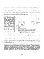
Turning facing and profiling operations are shown in Figure 4.1
The cutting characteristics of most turning
applications are similar. For a given surface
only one cutting tool is used. This tool must
overhang its holder to some extent to enable the
holder to clear the rotating workpiece. Once the
cut starts, the tool and the workpiece are usual-
ly in contact until the surface is completely gen-
erated. During this time the cutting speed and
cut dimensions will be constant when a cylin-
drical surface is being turned. In the case of fac-
ing operations the cutting speed is proportional
to the work diameter, the speed decreasing as
the center of the piece is approached.
Sometimes a spindle speed changing mecha-
nism is provided to increase the rotating speed
of the workpiece as the tool moves to the center of the part.
In general, turning is characterized by steady conditions of metal cutting. Except at the
beginning and end of the cut, the forces on the cutting tool and the tool tip temperature
are essentially constant. For the special case of facing, the varying cutting speed will
affect the tool tip temperature. Higher temperatures will be encountered at the larger
diameters on the workpiece. However, since cutting speed has only a small effect on cut-
ting forces, the forces acting on a facing tool may be expected to remain almost constant
during the cut.
4.2 Related Turning Operations
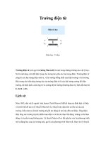
A variety of other machining operations can be performed on a lathe in addition to turn-
ing and facing. These include the following, as shown in Figure 4.2a through 4.2f.
Single point tools are used in most operations performed on a lathe. A short description
of six additional lathe operations are given below:
Chapter 4
Turning Tools
& Operations
Upcoming Chapters
Metal Removal
Cutting-Tool Materials
Metal Removal Methods
Machinability of Metals
Single Point Machining
Turning Tools and Operations
Turning Methods and Machines
Grooving and Threading
Shaping and Planing
Hole Making Processes
Drills and Drilling Operations
Drilling Methods and Machines
Boring Operations and Machines
Reaming and Tapping
Multi Point Machining
Milling Cutters and Operations
Milling Methods and Machines
Broaches and Broaching
Saws and Sawing
Abrasive Processes
Grinding Wheels and Operations
Grinding Methods and Machines
Lapping and Honing
George Schneider, Jr. CMfgE
Professor Emeritus
Engineering Technology
Lawrence Technological University
Former Chairman
Detroit Chapter ONE
Society of Manufacturing Engineers
Former President
International Excutive Board
Society of Carbide & Tool Engineers
Lawrence Tech.Univ.:
Prentice Hall:
Profiling
Turning
Facing
FIGURE 4.1: Diagram of the most com-
mon lathe operations: facing, turning, and
profiling.
Chamfering: The tool is used to cut an
angle on the corner of a cylinder.
Parting: The tool is fed radially into
rotating work at a specific location
along its length to cut off the end of a
part.
Threading: A pointed tool is fed linear-
ly across the outside or inside surface
of rotating parts to produce external
or internal threads.
Boring: Enlarging a hole made by a
previous process. A single point tool
is fed linearly and parallel to the axis
www.toolingandproduction.com
Chapter 4/Tooling & Production
3
of rotation.
Drilling: Producing a hole by feeding
the drill into the rotating work along
its axis. Drilling can be followed by
reaming or boring to improve accura-
cy and surface finish.
Knurling: Metal forming operation
used to produce a regular cross-
hatched pattern in work surfaces.
Chamfering and profiling operations
are shown in Figures 4.3a and 4.3b
respectively.
4.3 Turning Tool Holders
Mechanical Tool Holders and the ANSI
Identification System for Turning Tool
Holders and indexable inserts were
introduced in Chapter 2. A more
detailed discussion of Toolholder Styles
and their application will be presented
here.
4.3.1 Toolholder Styles
The ANSI numbering system for turn-
ing toolholders has assigned letters to
specific geometries in terms of lead
angle and end cutting edge angle. The
primary lathe machining operations of
turning, facing, grooving, threading and
cutoff are covered by one of the seven
basic tool styles outlined by the ANSI
system. The designations for the seven
primary tool styles are A, B, C, D, E, F,
and G.
A STYLE - Straight shank with 0
degree side cutting edge angle, for
turning operations.
B STYLE - Straight shank with 15
degree side cutting edge angle, for
turning operations.
C STYLE - Straight shank with 0
degree end cutting edge angle, for
cutoff and grooving operations.
D STYLE - Straight shank with 45
degree side cutting edge angle, for
turning operations.
E STYLE - Straight shank with 30
degree side cutting edge angle, for
threading operations.
F STYLE - Offset shank with 0 degree
end cutting edge angle, for facing
operations.
G STYLE - Offset shank with 0 degree
side cutting edge angle; this tool is an
‘A’ style tool with additional clear-
ance built in for turning operations
close to the lathe chuck.
There are many other styles of turn-
ing tools available in addition to those
shown here, as detailed by the ANSI
numbering system (see Figure 2.35).
The seven basic tools are shown in
operation in Figure 4.4
Right and Left Hand Toolholders
The toolholder styles discussed here
and shown above represent a fraction of
those standard styles available from
most indexable cutting tool manufactur-
ers. ANSI standard turning tools can be
purchased in either right or left hand
styles. The problem of identifying a
right hand tool from a left hand tool can
be resolved by remembering that when
Chap. 4: Turning Tools & Operations
Alternative
feeds possible
(a)
(f)
Feed
(b)
Feed
(c)
(d)
Feed Feed
(e)
FIGURE 4.2: Related turning operations: (a) chamfering, (b) parting, (c) threading, (d)
boring, (e) drilling, (f) knurling.
FIGURE 4.3: Chamfering (a) and profiling (b) operations, typically performed on a
lathe or a machining center. (Courtesy Valenite Inc.)
(a)
(b)
Chap. 4: Turning Tools & Operations
4
Tooling & Production/Chapter 4
www.toolingandproduction.com
holding the shank of a right hand tool as
shown in Figure 4.5 (insert facing
upward), will cut from left to right.
4.3.2 Turning Insert Shapes
Indexable turning inserts are manufac-
tured in a variety of shapes, sizes, and
thicknesses, with straight holes, with
countersunk holes, without holes, with
chipbreakers on one side, with chip-
breakers on two sides or without chip-
breakers. The selection of the appropri-
ate turning toolholder geometry accom-
panied by the correct insert shape and
chip breaker geometry, will ultimately
have a significant impact on the produc-
tivity and tool life of a specific turning
operation.
Insert strength is one important factor
in selecting the correct geometry for a
workpiece material or hardness range.
Triangle inserts are the most popular
shaped inserts primarily because of their
wide application range. A triangular
insert can be utilized in any of the seven
basic turning holders mentioned earlier.
Diamond shaped inserts are used for
profile turning operations while squares
are often used on lead angle tools. The
general rule for rating an insert’s
strength based on its shape is: ‘the larg-
er the included angle on the insert cor-
ner, the greater the insert strength’.
The following list describes the dif-
ferent insert shapes from strongest to
weakest. The relationship between
insert shapes and insert strength was
shown in Chapter 2. (see Fig. 2.28)
Insert Insert Insert
Letter Description Included
Designation Angle
R Round N/A
O Octagon 135
H Hexagon 120
P Pentagon 108
S Square 90
C Diamond 80
T Triangle 60
D Diamond 55
V Diamond 35
Six common turning tool holders are
shown in Figure 4.6a and five common
indexable insert shapes with molded
chip breakers are shown in Figure 4.6b.
4.4 Operating Conditions
Operating conditions control three
important metal cutting variables:
metal removal rate, tool life, and surface
finish. Correct operating condi-
tions must be selected to balance
these three variables and to
achieve the minimum machining
cost per piece, the maximum
production rate, and/or the best
surface finish whichever is desir-
able for a particular operation.
The success of any machining
operation is dependent on the
set-up of the workpiece and the
cutting tool. Set-up becomes
especially important when the
workpiece is not stiff or rigid and
when the tooling or machine tool
components must be extended to
reach the area to be machined.
Deflection of the workpiece,
the cutting tool, and the
machine, is always present and
can never be eliminated totally.
This deflection is usually so
minimal that it has no influence
on an operation, and often goes
unnoticed. The deflection only
becomes a problem when it
results in chatter, vibration, or
distortion. It is therefore, very
important to take the necessary
time and effort to ensure that the
set-up is as rigid as possible for
the type of operation to be per-
formed. This is especially important
when making heavy or interrupted
cuts.
Balancing should be considered
when machining odd-shaped work-
pieces, especially those workpieces
that have uneven weight distribution
and those which are loaded off-center.
An unbalanced situation can be a safe-
ty hazard and can cause work inaccu-
racies, chatter, and damage to the
machine tool. While unbalance prob-
lems may not be apparent, they may
exist at low speed operations and will
become increasingly severe as the
speed is increased. Unbalance condi-
A
B
C
D
E
F
G
Left-Hand Tool Right-Hand Tool
Cuts left to right
Cuts right to left
FIGURE 4.4: The primary lathe machining operations of turning, facing, grooving,
threading and cut-off are performed with one of seven basic toolholder styles.
FIGURE 4.5: Identification method for right- and
left-hand turning toolholders.
FIGURE 4.6: Common turning toolholders
(a) and common indexable insert shapes (b)
with molded chipbreakers are shown.
(Courtesy Valenite Inc.)
(a)
(b)
Chap. 4: Turning Tools & Operations
www.toolingandproduction.com
Chapter 4/Tooling & Production
5
tions most often occur when using
turntables and lathe face plates.
As material is removed from the
workpiece, the balance may change. If a
series of roughing cuts causes the work-
piece to become unbalanced, the prob-
lem will be compounded when the
speed is increased to take finishing cuts.
As a result, the reasons for problems in
achieving the required accuracy and
surface finish may not be apparent until
the machining operation has progressed
to the finishing stage. Operating condi-
tions become very important when
machining very large parts as shown in
Figure 4.7.
4.4.1 Work Holding Methods
In lathe work the three most common
work holding methods are:
• Held in a chuck
• Held between
centers
• Held in a collet
Many of the
various work
holding devices
used on a lathe
are shown in
Figure 4.8.
Chucks: The
most common
method of work
holding, the
chuck, has either
three or four jaws
(Fig. 4.9) and is
mounted on the
end of the main
spindle. A three jaw chuck is used for
gripping cylindrical workpieces when
the operations to be performed are such
that the machined surface is concentric
with the work surfaces.
The jaws have a series of teeth that
mesh with spiral grooves on a circular
plate within the chuck. This plate can be
rotated by the key inserted in the square
socket, resulting in simultaneous radial
motion of the jaws. Since the jaws
maintain an equal distance from the
chuck axis, cylindrical workpieces are
automatically centered when gripped.
Three jaw chucks, as shown in Figure
4.10, are often used to automatically
clamp cylindrical parts using either
electric or hydraulic power.
With the four jaw chuck, each jaw
can be adjusted independently by rota-
tion of the radially mounted threaded
screws. Although accurate
mounting of a workpiece can
be time consuming, a four jaw
chuck is often necessary for
non-cylindrical workpieces.
Both three and four jaw
chucks are shown in Figure
4.8.
Between Centers: For
accurate turning operations or
in cases where the work sur-
face is not truly cylindrical,
the workpiece can be turned
between centers. This form of
work holding is illustrated in
Fig. 4.11. Initially the work-
piece has a conical center
hole drilled at each end to
provide location for the lathe
centers. Before supporting
the workpiece between the
centers (one in the headstock
and one in the tailstock) a clamping
device called a ‘dog’ is secured to the
workpiece. The dog is arranged so that
the tip is inserted into a slot in the drive
plate mounted on the main spindle,
ensuring that the workpiece will rotate
with the spindle.
Lathe centers support the workpiece
between the headstock and the tailstock.
The center used in the headstock spindle
is called the ‘live’ center. It rotates with
the headstock spindle. The ‘dead’center
is located in the tailstock spindle. This
center usually does not rotate and must
be hardened and lubricated to withstand
the wear of the revolving work. Shown
in figure 4.12 are three kinds of dead
FIGURE 4.7: Operating conditions become very important when
machining very large parts. (Courtesy Sandvik Coromant Corp.)
FIGURE 4.8: Many of the various work-holding
devices used on a lathe for turning operations.
(Courtesy Kitagawa Div. Sumikin Bussan International
Corp.)
FIGURE 4.9: The most common method
of work holding, the chuck, has either
three jaws (a) or four jaws (b). (Courtesy
Kitagawa Div. Sumikin Bussan
International Corp.)
(a)
(b)