Tài liệu Mitsubishi FR-A700 P2 ppt
Bạn đang xem bản rút gọn của tài liệu. Xem và tải ngay bản đầy đủ của tài liệu tại đây (760.27 KB, 20 trang )
Features
Standard
Specifications
Outline
Dimension
Drawings
Operation
Panel
Protective
Functions
OptionsInstructionsMotorCompatibilityWarrantyInquiry
Terminal Connection
Diagram
Terminal Specification
Explanation
Parameter
List
Explanations
of
Parameters
Peripheral
Devices
24
Control circuit/input signal
Relay
A1, B1, C1
Relay output 1 (alarm
output)
1 changeover contact output indicates that the inverter protective function has activated and
the output stopped. Alarm: discontinuity across B-C (continuity across A-C), Normal:
continuity across B-C (discontinuity across A-C) Contact capacity 230VAC 0.3A (power
factor =0.4) 30VDC 0.3A
A2, B2, C2 Relay output 2
1 changeover contact output, contact capacity 230VAC, 0.3A (power factor=0.4) 30VDC
0.3A
Open collector
RUN Inverter running
Switched low when the inverter output frequency is equal to or
higher than the starting frequency (initial value 0.5Hz).
Switched high during stop or DC injection brake operation.
*1
Permissible load 24VDC
0.1A
(a voltage drop is 2.8V
maximum when the
signal is on)
SU Up to frequency
Switched low when the output frequency
reaches within the range of ±10% (initial value)
of the set frequency. Switched high during
acceleration/deceleration and at a stop.
*1
Alarm code (4bit)
output
(Refer to page 53.)
OL Overload alarm
Switched low when stall prevention is
activated by the stall prevention function.
Switched high when stall prevention is
cancelled.
*1
IPF
Instantaneous power
failure
Switched low when an instantaneous
power failure and under voltage
protections are activated.
*1
FU Frequency detection
Switched low when the inverter output
frequency is equal to or higher than the
preset detected frequency and high when
less than the preset detected frequency.
*1
SE
Open collector output
common
Common terminal for terminals RUN, SU, OL, IPF, FU
Pulse
FM
For meter
Select one e.g. output frequency from
monitor items.
*2
The output signal is proportional to the
magnitude of the corresponding
monitoring item.
Output item: output frequency (initial
setting),
permissible load current 2mA,
1440 pulses/s at 60Hz
Open collector output
Signals can be output from the open collector
terminals by setting Pr.291. (maximum output
pulse: 50kpulses/s)
Analog
AM Analog signal output
Output item: output frequency (initial
setting),
output signal 0 to 10VDC,
permissible load current 1mA(load impedance
10kΩ or more),
resolution 8 bit
Communication
PU connector
With the PU connector, communication can be made through RS-485. (1:1 connection
only)
⋅ Conforming standard: EIA-485(RS-485)
⋅ Transmission format: Multi-drop link
⋅ Communication speed: 4800 to 38400bps
⋅ Overall extension: 500m
RS-485
terminals
TXD+
,
TXD-
Inverter transmission
terminal
With the RS-485 terminals, communication can be made through RS-485.
RXD+,
RXD-
Inverter reception
terminal
⋅ Conforming standard: EIA-485(RS-485)
⋅ Transmission format: Multi-drop link
⋅ Communication speed: 300 to 38400bps
⋅ Overall extension: 500m
SG Earth (Ground)
USB connector
The FR-Configurator can be operated by connecting the inverter to the personnel
computer through USB.
⋅ Interface: conforms to USB1.1
⋅ Transfer rate: FS transfer (12Mbps)
⋅ Connector: USB series B connector
CAUTION
⋅ The inverter will be damaged if power is applied to the inverter output terminals (U, V, W). Never perform such wiring.
⋅ indicates that terminal functions can be selected from Pr.178 to Pr.196 (I/O terminal function selection).
⋅ Terminal names and terminal functions are those of the factory set.
*1 Low indicates that the open collector output transistor is on (conducts). High indicates that the transistor is off (does not conduct).
*2 Not output during inverter reset.
Type
Terminal
Symbol
Terminal Name Description
25
Wiring example
Standard motor with encoder (SF-JR), 5V differential line driver (speed control)
R/L1
S/L2
T/L3
R1/L11
S1/L21
Analog input
10E(+10V)
10(+5V)
2
2
3
1
1
SF-JR motor
with encoder
C1
B1
A1
U
V
W
U
V
W
E
C
P1
C2
B2
A2
*
5
(+)
(-)
R
PX PR N/-P/+
R
PA1
FR-A7AP
PA2
PB1
PB2
PZ1
PZ2
PG
PG
SD
SD
Terminating
resistor
ON
OFF
5VDC power supply
A
N
B
P
H
K
IM
STF
STR
STOP
RH
RM
RL
JOG
RT
MRS
RES
AU
CS
SD
*. Earth the shield cable of the encoder
cable to the enclosure with a P clip, etc.
Encoder
RUN
SU
IPF
OL
FU
SE
Earth
(ground)
(+)
(-)
Differential line driver
Complimentary
Main circuit terminal
Control circuit terminal
Sink logic
Three-phase AC
power supply
MC
MCCB
Jumper
Jumper Jumper
Open collector
output
Open collector
output common
Frequency
detection
Running
Up to frequency
Instantaneous
power failure
Overload
Relay output
Relay output 2
Relay output 1
(alarm output)
(Analog common)
0 to
±
10VDC
0 to 5VDC
0 to 10VDC
4 to 20mADC
selected
selected
0 to
±
5VDC
(Initial value)
(Initial value)
Forward rotation start
Reverse rotation start
Start self-holding selection
Middle speed
High speed
Low speed
Jog mode
Second function selection
Output stop
Reset
Terminal 4 input selection
(current input selection)
Selection of automatic restart
after instantaneous power failure
Contact input common
Control input signals (no voltage input allowed)
Main circuit
Control circuit
Frequency setting
potentiometer
1/2W1k
Ω
torque limit command
( 10V)
Features
Standard
Specifications
Outline
Dimension
Drawings
Operation
Panel
Protective
Functions
OptionsInstructionsMotorCompatibilityWarrantyInquiry
Terminal Connection
Diagram
Terminal Specification
Explanation
Parameter
List
Explanations
of
Parameters
Peripheral
Devices
26
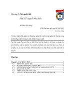
*1 For the fan of the 7.5kW or less dedicated motor, the power supply is single phase (200V/50Hz, 200 to 230V/60Hz).
*2 Assign OH (external thermal input) signal to the terminal CS. (Set "7" in Pr. 186.)
Connect a 2WlkΩ resistor between the terminal PC and CS (CH). Install the resistor pushing it against the bottom
part of the terminal block so as to avoid a contact with other cables.
Refer to the inverter manual for details of Pr. 186 CS terminal function selection.
*3 The pin number differs according to the encoder used.
*4 Connect the encoder so that there is no looseness between the motor and motor shaft. Speed ratio should be 1:1.
*5 Earth the shield cable of the encoder cable to the enclosure with a P clip, etc.
*6 For the complementary, set the switch to off position.
*7 A separate power supply of 5V/12V/15V/24V is necessary according to the encoder power specification.
*8 For terminal compatibility of the FR-JCBL, FR-V5CBL and FR-A7AP, refer to the inverter manual or the instruction manual of the FR-A7AP.
*9 Assign the function using Pr.178 to Pr.184, Pr.187 to Pr.189 (input terminal function selection).
*10 When position control is selected, terminal JOG function is made invalid and conditional position pulse train input terminal becomes valid.
*11 Assign the function using Pr.190 to Pr.194 (output terminal function selection).
Vector control dedicated motor (SF-V5RU), 12V complimentary
10
2
2
3
1
1
Speed limit command
Frequency setting potentiometer
1/2W1kΩ
5
(+)
(-)
MCCB
R/L1
S/L2
T/L3
*6 *8
*5
PA1
FR-A7AP
PA2
PB1
PB2
PZ1
PZ2
PG
PG
SD
SD
STF
STR
SD
*3
ON
OFF
SF-V5RU
U
V
W
U
A
B
C
V
W
E
G1
G2
A
*4
MCCB
B
C
D
F
G
S
R
IM
FAN
Encoer
*1
CS(OH)
SD
Inverter
PC
2W1kΩ
12VDC
power supply
(+)
(-)
*7
Three-phase AC
power supply
Three-phase AC
power supply
Thermal
protector
Earth
(ground)
Differential
line driver
Complimentary
Terminating
resistor
External thermal
relay input *2
Forward rotation start
Reverse rotation start
Contact input common
Torque
command
(
±
10V)
1
5
(+)
(-)
MCCB
R/L1
S/L2
T/L3
*6 *8
*5
PA1
FR-A7AP
PA2
PB1
PB2
PZ1
PZ2
Forward stroke end
Reverse stroke end
Pre-excitation/servo on
Clear signal
Pulse train
Sign signal
Preparation ready signal
STF
STR
LX *
9
CLR
*9
CLEAR
JOG
*10
NP *
9
*3
OFF
SF-V5RU
U
V
W
U
A
B
C
V
W
E
G1
G2
A
*4
MCCB
B
PA1
PA2
PB1
PB2
PZ1
PZ2
C
D
F
G
S
R
IM
FAN
Encoder
*1
CS(OH)
SD
Inverter
Positioning unit
MELSEQ-Q QD75P1
PC
2W1kΩ
12VDC
power supply
(+)
(-)
*7
PULSE F
PULSE R
PULSE COM
CLEAR COM
RDY COM
READY
PC
RDY
*11
SE
FLS
RLS
DOG
STOP
COM
24VDC power supply
Three-phase AC
power supply
Three-phase AC
power supply
Earth
(ground)
Thermal
protector
External thermal
relay input *2
Torque limit command
(
±
10V)
ON
Differential
line driver
Complimentary
Terminating
resistor
PG
PG
SD
SD
Torque control
Position control
CS(OH)
Resistor (2W1kΩ)
PC
Control circuit
terminal block
27
Setting dial
(Setting dial: Mitsubishi inverter
dial)
Used to change the
frequency setting and
parameter values.
Operation mode switchover
Used to switch between the PU and external operation mode.
When using the external operation mode (operation using a separately
connected frequency setting potentiometer and start signal), press this key to
light up the EXT indication. (Change the Pr.79 value to use the combined mode.)
PU: PU operation mode
EXT: External operation mode
Monitor(4-digit LED)
Shows the frequency, parameter
number, etc.
No function
Monitor indication
Lit to indicate monitoring mode.
PU: Lit to indicate PU operation mode.
EXT: Lit to indicate external operation mode.
NET: Lit to indicate network operation mode.
Rotation direction indication
REV: Lit during reverse rotation
FWD: Lit during forward rotation
Start command
forward rotation
Start command
reverse rotation
Stop operation
Alarms can be reset
Mode
switchover
Used to change
each setting mode.
Unit indication
·
Hz: Lit to indicate frequency.
·
A: Lit to indicate current.
·
V: Lit to indicate voltage.
(Flicker when the set frequency monitor is
displayed.)
* Energy saving monitor is displayed when the
energy saving monitor of Pr. 52 is set.
Used to set each setting.
If pressed during operation, monitor
changes as below;
Running
frequency
Output
current
Output
voltage
Operation mode indication
On: Forward/reverse operation
Flickering: When the frequency command is
not given even if the
forward/reverse command is given.
*
Operation Panel (FR-DU07)
Features
Standard
Specifications
Outline
Dimension
Drawings
Operation
Panel
Protective
Functions
OptionsInstructionsMotorCompatibilityWarrantyInquiry
Terminal Connection
Diagram
Terminal Specification
Explanation
Parameter
List
Explanations
of
Parameters
Peripheral
Devices
28
Basic operation
At powering on (external operation mode)
PU operation mode
(output frequency monitor)
Parameter setting mode
PU Jog operation mode
Output current monitor
Output voltage monitor
Display the current
setting
Value change
Value change
Parameter write is completed!!
Parameter and a setting value
flicker alternately.
Parameter clear Parameter
all clear
Alarm clear
Parameter copy
(Example)
(Example)
Frequency setting has been
written and completed!!
and frequency flicker.
[Operation for displaying alarm history]
Past eight alarms can be displayed.
(The latest alarm is ended by ".".)
When no alarm history exists, is displayed.
Operation mode switchover
Parameter settingAlarm history
Monitor/frequency setting
29
For simple variable-speed operation of the inverter, the initial setting of the parameters may be used as they are. Set the
necessary parameters to meet the load and operational specifications. Parameter setting, change and check can be made
from the operation panel (FR-DU07). For details of parameters, refer to the instruction manual.
REMARKS
⋅
indicates simple mode parameters. (initially set to extended mode)
⋅
The shaded parameters in the table allow its setting to be changed during operation even if "0" (initial value) is set in Pr.77 Parameter write
selection.
Func-
tion
Parameter
Name Setting Range
Minimum
Setting
Increments
Initial Value
Refer
to
Page
Customer
Setting
Basic functions
0
Torque boost 0 to 30% 0.1% 6/4/3/2
/1
%
*1
42
1
Maximum frequency 0 to 120Hz 0.01Hz
120
/60
Hz
*2
42
2
Minimum frequency 0 to 120Hz 0.01Hz 0Hz
42
3
Base frequency 0 to 400Hz 0.01Hz 60Hz 42
4
Multi-speed setting (high speed) 0 to 400Hz 0.01Hz 60Hz
42
5
Multi-speed setting (middle speed) 0 to 400Hz 0.01Hz 30Hz
42
6
Multi-speed setting (low speed) 0 to 400Hz 0.01Hz 10Hz 42
7
Acceleration time 0 to 3600/360s 0.1/0.01s 5/15s
*3
43
8
Deceleration time 0 to 3600/360s 0.1/0.01s 5/15s
*3
43
9
Electronic thermal O/L relay 0 to 500/0 to 3600A
*2
0.01
/0.1
A
*2
Inverter
rated output
current
43
DC injection
brake
10 DC injection brake operation frequency 0 to 120Hz, 9999 0.01Hz 3Hz
43
11 DC injection brake operation time 0 to 10s, 8888 0.1s 0.5s
43
12 DC injection brake operation voltage 0 to 30% 0.1%
4/2
/1
%
*3
43
13 Starting frequency 0 to 60Hz 0.01Hz 0.5Hz
43
14 Load pattern selection 0 to 5 1 0
44
Jog
operation
15 Jog frequency 0 to 400Hz 0.01Hz 5Hz
44
16 Jog acceleration/deceleration time 0 to 3600/360s 0.1/0.01s 0.5s
44
17 MRS input selection 0, 2 1 0
44
18 High speed maximum frequency 120 to 400Hz 0.01Hz 120
/60
Hz
*2
42
19 Base frequency voltage 0 to 1000V, 8888, 9999 0.1V 9999
42
Acceleration/
deceleration
times
20
Acceleration/deceleration reference
frequency
1 to 400Hz 0.01Hz 60Hz
43
21
Acceleration/deceleration time
increments
0, 1 1 0
43
Stall
prevention
22
Stall prevention operation level
(torque limit level )
0 to 400% 0.1% 150%
44, 45
23
Stall prevention operation level
compensation factor at double speed
0 to 200%, 9999 0.1% 9999 44
Multi-speed
setting
24 to 27 Multi-speed setting(4 speed to 7 speed) 0 to 400Hz, 9999 0.01Hz 9999 42
28
Multi-speed input compensation selection
0, 1 1 0 45
29
Acceleration/deceleration pattern
selection
0 to 5 1 0
46
30 Regenerative function selection
0, 1, 2, 10, 11, 12, 20, 21
1 0
46
Frequency
jump
31 Frequency jump 1A 0 to 400Hz, 9999 0.01Hz 9999 47
32 Frequency jump 1B 0 to 400Hz, 9999 0.01Hz 9999
47
33 Frequency jump 2A 0 to 400Hz, 9999 0.01Hz 9999
47
34 Frequency jump 2B 0 to 400Hz, 9999 0.01Hz 9999 47
35 Frequency jump 3A 0 to 400Hz, 9999 0.01Hz 9999
47
36 Frequency jump 3B 0 to 400Hz, 9999 0.01Hz 9999
47
37 Speed display 0, 1 to 9998 1 0 47
Frequency
detection
41 Up-to-frequency sensitivity 0 to 100% 0.1% 10%
47
42 Output frequency detection 0 to 400Hz 0.01Hz 6Hz
47
43
Output frequency detection for reverse
rotation
0 to 400Hz, 9999 0.01Hz 9999
47
Parameter List
Features
Standard
Specifications
Outline
Dimension
Drawings
Operation
Panel
Protective
Functions
OptionsInstructionsMotorCompatibilityWarrantyInquiry
Terminal Connection
Diagram
Terminal Specification
Explanation
Parameter
List
Explanations
of
Parameters
Peripheral
Devices
30
Second functions
44
Second acceleration/deceleration time 0 to 3600/360s
0.1/0.01s 5s 43
45
Second deceleration time 0 to 3600/360s, 9999
0.1/0.01s 9999 43
46
Second torque boost 0 to 30%, 9999
0.1% 9999 42
47
Second V/F (base frequency) 0 to 400Hz, 9999
0.01Hz 9999 42
48
Second stall prevention operation
current
0 to 220%
0.1% 150% 44
49
Second stall prevention operation
frequency
0 to 400Hz, 9999
0.01Hz 0Hz 44
50
Second output frequency detection 0 to 400Hz
0.01Hz 30Hz 47
51
Second electronic thermal O/L relay
0 to 500A, 9999/
0 to 3600A, 9999
*2
0.01/0.1A
*2
9999 43
Monitor functions
52
DU/PU main display data selection
0, 5 to 14, 17 to 20,
22 to 25, 32 to 35,
50 to 57, 100
1 0 48
54
FM terminal function selection
1 to 3, 5 to 14, 17, 18,
21, 24, 32 to 34, 50, 52,
53
1 1 48
55
Frequency monitoring reference 0 to 400Hz
0.01Hz 60Hz 48
56
Current monitoring reference 0 to 500/0 to 3600A
*2
0.01/0.1A
*2
Inverter
rated output
current
48
Automatic restart
57
Restart coasting time
0, 0.1 to 5s, 9999/
0, 0.1 to 30s, 9999
*2
0.1s 9999 49
58
Restart cushion time 0 to 60s
0.1s 1s 49
59
Remote function selection 0, 1, 2, 3
1 0 50
60
Energy saving control selection 0, 4
1 0 50
Automatic acceleration/
deceleration
61
Reference current
0 to 500A, 9999/
0 to 3600A, 9999
*2
0.01A/0.1A
*2
9999 50
62
Reference value at acceleration 0 to 220%, 9999
0.1% 9999 50
63
Reference value at dcceleration 0 to 220%, 9999
0.1% 9999 50
64
Starting frequency for elevator mode 0 to 10Hz, 9999
0.01Hz 9999 50
65
Retry selection 0 to 5
1 0 51
66
Stall prevention operation reduction
starting frequency
0 to 400Hz
0.01Hz 60Hz 44
Retry
67
Number of retries at alarm occurrence 0 to 10, 101 to 110
1 0 51
68
Retry waiting time 0 to 10s
0.1s 1s 51
69
Retry count display erase 0
1 0 51
70
Special regenerative brake duty 0 to 30%/0 to 10%
*2
0.1% 0% 46
71
Applied motor
0 to 8, 13 to 18, 20, 23,
24, 30, 33, 34, 40, 43, 44,
50, 53, 54
1 0 51
72
PWM frequency selection 0 to 15/0 to 6, 25
*2
1 2 52
73
Analog input selection 0 to 7, 10 to 17
1 1 52
74
Input filter time constant 0 to 8
1 1 52
75
Reset selection/disconnected PU
detection/PU stop selection
0 to 3, 14 to 17
1 14 53
76
Alarm code output selection 0, 1, 2
1 0 53
77
Parameter write selection 0, 1, 2
1 0 53
78
Reverse rotation prevention selection 0, 1, 2
1 0 53
79
Operation mode selection 0, 1, 2, 3, 4, 6, 7
1 0 54
Func-
tion
Parameter
Name Setting Range
Minimum
Setting
Increments
Initial Value
Refer
to
Page
Customer
Setting
31
Motor constants
80
Motor capacity
0.4 to 55kW, 9999/
0 to 3600kW, 9999
*2
0.01/0.1kW
*2
9999 55
81
Number of motor poles 2, 4, 6, 12, 14, 16, 9999
1 9999 55
82
Motor excitation current
0 to 500A, 9999/
0 to 3600A, 9999
*2
0.01/0.1A
*2
9999 55
83
Motor rated voltage 0 to 1000V
0.1V 200/400V 55
84
Rated motor frequency 10 to 120Hz
0.01Hz 60Hz 55
89
Speed control gain (magnetic flux vector)
0 to 200%
0.1% 9999 55
90
Motor constant (R1)
0 to 50
Ω
, 9999/
0 to 400mΩ, 9999
*2
0.001Ω/
0.01mΩ
*2
9999 55
91
Motor constant (R2)
0 to 50
Ω
, 9999/
0 to 400mΩ, 9999
*2
0.001Ω/
0.01mΩ
*2
9999 55
92
Motor constant (L1)
0 to 50
Ω
(0 to 1000mH), 9999
/
0 to 3600m
Ω
(0 to 400mH), 9999
*2
0.001
Ω
(0.1mH)/
0.01m
Ω
(0.01mH)
*2
9999 55
93
Motor constant (L2)
0 to 50
Ω
(0 to 1000mH), 9999
/
0 to 3600m
Ω
(0 to 400mH), 9999
*2
0.001
Ω
(0.1mH)/
0.01m
Ω
(0.01mH)
*2
9999 55
94
Motor constant (X)
0 to 500
Ω
(0 to 100%), 9999/
0 to 100
Ω
(0 to 100%), 9999
*2
0.01Ω (0.1%)/
0.01Ω (0.01%)
*2
9999 55
95
Online auto tuning selection 0 to 2
1 0 56
96
Auto tuning setting/status 0, 1, 101
1 0 55
Adjustable 5 points V/F
100
V/F1(first frequency) 0 to 400Hz, 9999
0.01Hz 9999 56
101
V/F1(first frequency voltage) 0 to 1,000V
0.1V 0V 56
102
V/F2(second frequency) 0 to 400Hz, 9999
0.01Hz 9999 56
103
V/F2(second frequency voltage) 0 to 1,000V
0.1V 0V 56
104
V/F3(third frequency) 0 to 400Hz, 9999
0.01Hz 9999 56
105
V/F3(third frequency voltage) 0 to 1,000V
0.1V 0V 56
106
V/F4(fourth frequency) 0 to 400Hz, 9999
0.01Hz 9999 56
107
V/F4(fourth frequency voltage) 0 to 1,000V
0.1V 0V 56
108
V/F5(fifth frequency) 0 to 400Hz, 9999
0.01Hz 9999 56
109
V/F5(fifth frequency voltage) 0 to 1,000V
0.1V 0V 56
Third functions
110
Third acceleration/deceleration time 0 to 3600/360s, 9999
0.1/0.01s 9999 43
111
Third deceleration time 0 to 3600/360s, 9999
0.1/0.01s 9999 43
112
Third torque boost 0 to 30%, 9999
0.1% 9999 42
113
Third V/F (base frequency) 0 to 400Hz, 9999
0.01Hz 9999 42
114
Third stall prevention operation current 0 to 220%
0.1% 150% 44
115
Thrid stall prevention operation
frequency
0 to 400Hz
0.01Hz 0 44
116
Third output frequency detection 0 to 400Hz
0.01Hz 60Hz 47
PU connector
communication
117
PU communication station 0 to 31
1 0 56
118
PU communication speed 48, 96, 192, 384
1 192 56
119
PU communication stop bit length 0, 1, 10, 11
1 1 56
120
PU communication parity check 0, 1, 2
1 2 56
121
Number of PU communication retries 0 to10, 9999
1 1 56
122
PU communication check time interval 0, 0.1 to 999.8s, 9999
0.1s 9999 56
123
PU communication waiting time setting 0 to 150ms, 9999
1 9999 56
124
PU communication CR/LF presence/
absence selection
0, 1, 2
1 1 56
125
Terminal 2 frequency setting gain
frequency
0 to 400Hz
0.01Hz 60Hz 57
126
Terminal 4 frequency setting gain
frequency
0 to 400Hz
0.01Hz 60Hz 57
Func-
tion
Parameter
Name Setting Range
Minimum
Setting
Increments
Initial Value
Refer
to
Page
Customer
Setting