PCS 994s x technical manual EN overseas general x r1 00
Bạn đang xem bản rút gọn của tài liệu. Xem và tải ngay bản đầy đủ của tài liệu tại đây (2.72 MB, 157 trang )
Copyright © 2019 NR. All rights reserved.
NR, the NR logo are either registered trademarks or trademarks of NR Electric Co., Ltd. No NR
trademarks may be used without written permission. NR products appearing in this document may
be covered by P.R. China and foreign patents. NR Electric Co., Ltd. reserves all rights and
benefits afforded under P.R. China and international copyright and patent laws in its products,
including but not limited to software, firmware and documentation. NR Engineering Co., Ltd. is
licensed to use this document as well as all intellectual property rights owned or held by NR
Electric Co., Ltd, including but not limited to copyright, rights in inventions, patents, know-how,
trade secrets, trademarks and trade names, service marks, design rights, database rights and
rights in data, utility models, domain names and all similar rights.
The information in this document is provided for informational use only and does not constitute a
legal contract between NR and any person or entity unless otherwise specified. Information in this
document is subject to change without prior notice.
To the extent required the products described herein meet applicable IEC and IEEE standards,
but no such assurance is given with respect to local codes and ordinances because they vary
greatly.
Although every reasonable effort is made to present current and accurate information, this
document does not purport to cover all details or variations in equipment nor provide for every
possible contingency to be met in connection with installation, operation, or maintenance. Should
further information be desired or should particular problems arise which are not covered
sufficiently for your purposes, please do not hesitate to contact us.
Preface
Preface
About This Manual
The technical manual describes the protection, automation, control, and supervision functions of
PCS S series device for line differential protection, and contains operation principle descriptions,
and lists function blocks, logic diagrams, input and output signals, setting parameters and
technical data, sorted per function, as well as the hardware of the device. The manual can be
used as a technical reference during the engineering phase and during normal service. In addition,
the manual also includes a glossary that lists and defines technical terms used throughout the
manual.
Safety Information
This manual is not a complete index of all safety measures required for operation of the
equipment (module or device). However, it comprises important information that must be followed
for personal safety, as well as to avoid material damage. Information is highlighted and illustrated
as follows according to the degree of danger:
Indicates an imminently hazardous situation that, if not avoided, will
result in death or serious injury.
Indicates a potentially hazardous situation that, if not avoided, could
result in death or serious injury.
Indicates a potentially hazardous situation that, if not avoided, may result
in minor or moderate injury or equipment damage.
Indicates that property damage can result if the measures specified are
not taken.
Important information about the device, product handling or a certain
section of the documentation which must be given particular attention.
Instructions and Warnings
The following hazard statements apply to this device.
Disconnect or de-energize all external connections BEFORE opening this
PCS-994S Frequency and Voltage Controller
I
Date: 2019-08-15
Preface
device. Contact with hazardous voltages and currents inside this device
can cause electrical shock resulting in injury or death.
Contact with instrument terminals can cause electrical shock that can
result in injury or death.
Use of this equipment in a manner other than specified in this manual can
impair operator safety safeguards provided by this equipment.
Have only qualified personnel service this equipment. If you are not
qualified to service this equipment, you can injure yourself or others, or
cause equipment damage.
This device is shipped with default passwords. Default passwords should
be changed to private passwords at installation. Failure to change each
default password to a private password may allow unauthorized access.
NR shall not be responsible for any damage resulting from unauthorized
access.
DO NOT look into the fiber (laser) ports/connectors.
DO NOT look into the end of an optical cable connected to an optical
output.
DO NOT perform any procedures or adjustments that this instruction
manual does not describe.
During installation, maintenance, or testing of the optical ports, ONLY use
PCS-994S Frequency and Voltage Controller
II
Date: 2019-08-15
Preface
the test equipment qualified for Class 1 laser products!
Incorporated components, such as LEDs, transceivers, and laser emitters,
are NOT user serviceable. Return units to NR for repair or replacement.
Equipment components are SENSITIVE to electrostatic discharge (ESD).
Undetectable permanent damage can result if you do not use proper ESD
procedures. Ground yourself, your work surface, and this equipment
BEFORE removing any cover from this equipment. If your facility is not
equipped to work with these components, contact NR about returning this
device and related NR equipment for service.
Insufficiently rated insulation can deteriorate under abnormal operating
conditions and cause equipment damage. For external circuits, use wiring
of SUFFICIENTLY RATED insulation that will not break down under
abnormal operating conditions.
SEVERE power and ground problems can occur on the communications
ports of this equipment as a result of using non-standard cables. Please
use the wiring method recommended in the manual for communication
terminals.
DO NOT connect power to the relay until you have completed these
procedures and receive instruction to apply power. Equipment damage
can result otherwise.
Use of controls or adjustments, or performance of procedures other than
those specified herein, may RESULT IN hazardous radiation exposure.
The firmware may be upgraded to add new features or enhance/modify
PCS-994S Frequency and Voltage Controller
III
Date: 2019-08-15
Preface
existing features, please MAKE SURE that the version of this manual is
compatible with the product in your hand.
Document Conventions
The abbreviations and acronyms in this manual are explained in “Appendix A Glossary”. The
Glossary also contains definitions of important terms.
Menu path is connected with the arrow "→" and bold.
For example: the access path of protection settings is: MainMenu→Settings→Protection
Settings
Settings not in the table should be placed in brackets.
For example: the system setting [Opt_SysFreq]
Cross-references are presented in italics.
For example: refer to Figure 1.1-1, refer to Table 1.1-1, reference to Section 1.1
Binary input signals, binary output signals, analogs, LED lights, buttons, and other fixed
meanings, should be written in double quotes and bold.
For example: press the button "ENT".
Symbols
AND Gate
&
&
&
>=1
>=1
OR Gate
>=1
Comparator
Binary signal Input
BI
xxx
PCS-994S Frequency and Voltage Controller
IV
Date: 2019-08-15
Preface
Signal input
SIG
Setting input
SET
xxx
Enable input
EN
xxx
xxx
Timer
Optional definite-time or inverse-time characteristic
Timer
t
t
Timer
Fixed delay pickup (10ms), fixed delay dropout (2ms)
10ms
2ms
Timer
Settable delay pickup, fixed delay dropout
[Tset1]
0ms
Timer
Fixed delay pickup, settable delay dropout
0ms
[Tset2]
Timer
Settable delay pickup, settable delay dropout
[Tset1]
[Tset2]
Generator
G
PCS-994S Frequency and Voltage Controller
V
Date: 2019-08-15
Preface
Transformer
Reactor
Motor
M
Capacitor
C
Busbar
Circuit breaker
52
Current transformer
3CT
*
Voltage transformer
3VT
Disconnector
PCS-994S Frequency and Voltage Controller
VI
Date: 2019-08-15
Preface
Earth
Three-phase Corresponding Relationship
Basic
A, B, C
L1, L2, L3
R, Y, B
AN, BN, CN
L1N, L2N, L3N
RN,YN, BN
ABC
L123
RYB
U (voltage)
V
U
Example
Ia, Ib, Ic, I0
IL1, IL2, IL3, IN
IR, IY, IB, IN
Ua, Ub, Uc
VL1, VL2, VL3
UR, UY, UB
Uab, Ubc, Uca
VL12, VL23, VL31
URY, UYB, UBR
U0, U1, U2
VN, V1, V2
UN, U1, U2
Warranty
This product is covered by the standard NR 10-year warranty. For warranty details, please consult
the manufacturer or agent for warranty information.
Document Structure
This manual is a comprehensive work covering the theories of protection, control, supervision,
measurement, etc. and the structure & technical data of relevant hardware. Read the sections that
pertain to your application to gain valuable information about using the PCS-994S. To concentrate
on the target sections of this manual as your job needs and responsibilities dictate. An overview of
each manual section and section topics follows.
1 Introduction
Introduces features, summarizes functions and applications of the device.
2 Technical Data
Lists device specifications, type tests, and ratings.
3 Protection Functions
Describes the function of various protection elements, gives detailed specifics on protection
scheme logic, provides the relevant logic diagrams.
PCS-994S Frequency and Voltage Controller
VII
Date: 2019-08-15
Preface
4 Measurement
Provides information on viewing fundamental and rms metering quantities for voltages and
frequencies.
5 Supervision
Describes self-supervision technique to help diagnose potential difficulties should these occur and
includes the list of status notification messages. Provides a troubleshooting chart for common
device operation problems.
6 System Functions
Describes how to perform fundamental operations such as clock synchronization, communicating
with the device, switching active setting group, checking relay status, reading event reports and
SER (Sequential Events Recorder) records.
7 Hardware
Describes the hardware of the PCS series device family and provides general information on the
product structure and the modules technical data.
8 Settings
Provides a list of all settings and their ranges, unit, steps, defaults. The organization of the
settings is similar to the settings organization in the device and in the PCS-Studio software.
Appendix A Glossary
Describes the abbreviations adopted in this manual.
Document Revision History
PN: ZL_PCS-994S_X_Technical Manual_EN_Overseas General_X
Current version: R1.00
Corresponding Version
Date
Document
Software
R1.00
R1.00
2019-08-15
Description of change
Form the original manual.
PCS-994S Frequency and Voltage Controller
VIII
Date: 2019-08-15
1 Introduction
1 Introduction
1
Table of Contents
1.1 Application ....................................................................................................... 1-1
1.2 Functions ......................................................................................................... 1-2
1.3 Features ............................................................................................................ 1-4
List of Figures
Figure 1.1-1 Typical applications of PCS-994S ...................................................................... 1-1
Figure 1.1-2 Function diagram of PCS-994S .......................................................................... 1-1
PCS-994S Frequency and Voltage Controller
1-a
Date: 2019-08-15
1 Introduction
1.1 Application
PCS-994S frequency and voltage controller provides fast and selective generation shedding and
load shedding due to the frequency or voltage abnormality in the power network, for avoiding the
system crash and a large area blackout, maintaining the stability of the system voltage and
frequency. The device contains all important auxiliary functions that are necessary today for safe
network operation. This includes measurement and monitoring functions. The large number of
communication interfaces and communication protocols satisfies the requirements of
communication-based selective control and of automated operation. Their modular structure
permits the device always to be adapted flexibly to the individual requirements.
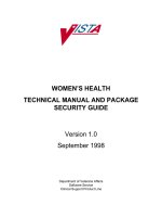
PCS-994S applies to double-bus scenarios and single bus with bus section scenarios.
Bus1
Bus2
PCS-994S
Bus1
Bus2
PCS-994S
Figure 1.1-1 Typical applications of PCS-994S
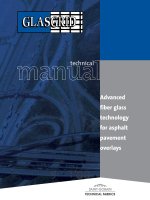
The function diagram for protecting a double-bus is shown below.
Bus1
Bus2
81U
81O
81R
27
59
3VT
3VT
Figure 1.1-2 Function diagram of PCS-994S
The PCS-994S is applicable not only to conventional substations, but also to digital substations. It
supports IEC 61850 Editions 1 and 2 and provides GOOSE and SV network interfaces with high
real-time performance. The process level network supports peer-to-peer (P2P) mode and
networking mode, including single network mode and dual network mode. The station level
network could also receive and send MMS messages (such as interlocking signals) or process
level GOOSE messages (such as trip signals).
PCS-994S Frequency and Voltage Controller
1-1
Date: 2019-08-15
1
1 Introduction
1.2 Functions
1
1.
Protection Functions
ANSI
81U
81O
81R
27
59
2.
3.
Function
Remark
Under-frequency protection
Over-frequency protection
Rate-of-change
of
frequency
Up to 5 basic stage of under-frequency load shedding
Up to 2 accelerated stage of under-frequency load shedding
Up to 3 special stage of under-frequency load shedding
Under-voltage blocking element
df/dt blocking element
Frequency over-range blocking element
Up to 5 basic stage of over-frequency generation shedding
Under-voltage blocking element
Frequency over-range blocking element
Up to 5 stages with independent logic
Optional positive or negative change of frequency for each
protection
Under-voltage protection
Over-voltage protection
stage
Under-voltage blocking element
Up to 5 basic stage of under-voltage load shedding
Up to 2 accelerated stage of under-voltage load shedding
Up to 3 special stage of under-voltage load shedding
Under-voltage blocking element
dU/dt blocking element
VT circuit failure blocking
Up to 3 basic stage of over-voltage system splitting
Measurement and Metering Functions
U, f,
du/dt, df/dt
Positive, negative and zero sequences
Max.15th harmonics
Supervision Functions
VT circuit failure supervision (VTS)
Self diagnostic
Powerful faults recording (max. buffer for 10,000 sampled points at 4.8 or 9.6 kHz
Event Recorder including 1024 disturbance records, 1024 binary events, 1024
supervision events, 256 control logs and 1024 device logs.
Disturbance recorder including 64 disturbance records with waveforms (The file format of
disturbance recorder is compatible with international COMTRADE file.)
PCS-994S Frequency and Voltage Controller
1-2
Date: 2019-08-15
1 Introduction
4.
Single line diagram representation in display
Communication Functions
1
Support of various protocols
Modbus, DNP3.0, IEC 60870-5-103, IEC 61850 Ed.1 & Ed.2, IEC 61850 MMS Server,
IEC 61850-8-1 GOOSE, IEC 61850-9-2LE SV, IEC 62439 Parallel Redundancy Protocol,
IEC 62439 HSR Ring Redundancy Protocol
5.
6.
Up to four 10Base-T/100Base-TX copper Ethernet ports
Up to four 100Base-FX optical Ethernet ports
Two RS-485 serial ports for communication or printer
One RS-485/TTL/ST port for clock synchronization
Two RJ45 debugging ports (front and rear)
User Interfaces
Friendly HMI interface with LCD, easy-to-use keypad aids simple navigation and
set-point adjustment
Push buttons for open/close, switch for selection between local and remote control, and
user's login and logout authority management
4 Programmable operator pushbuttons with user-configurable labels
Up to 18 programmable target LEDs with user-configurable labels
1 RS-485 rear port for printer
Language switchover—English+ selected language
Configuration tool—PCS-Studio
Additional Functions
User programmable logic
Switching system phase sequences function (ABC or ACB)
Clock synchronization
IRIG-B: IRIG-B via RS-485 differential level, TTL level or optical fibre interface
PPS: Pulse per second (PPS) via RS-485 differential level or binary input
PPM: Pulse per minute (PPM) via RS-485 differential level or binary input
IEEE1588: Clock message based on IEEE1588 via optical fibre interface
SNTP (PTP): Unicast (point-to-point) SNTP mode via Ethernet network
SNTP (BC): Broadcast SNTP mode via Ethernet network
PCS-994S Frequency and Voltage Controller
1-3
Date: 2019-08-15
1 Introduction
1
Message (IEC103/Modbus/DNP3.0): Clock messages through IEC103 protocol,
Modbus protocol and DNP3.0 protocol
Cyber security
NERC CIP
IEC 62351
IEC 62443
IEEE 1686
1.3 Features
Unified software and hardware platform, comprehensive power grid solutions of protection,
measurement and monitoring, easy to use and maintain.
High reliability and redundancy design for drive systems of the sampling circuit and the output
circuit ensure that overall reliability of the device is high. Real-time sampling based on dual AD
can mutually check and detect the potential abnormality in the sampling circuit in time. The
control power supply of the output relay is independent with the control circuit of trigger signals,
which can prevent from undesired operation caused by the abnormality of drive circuit of
output relays.
Various function modules can satisfy various situations according to the different requirements
of users. Flexible and universal logic programming, user-defined configuration of BI/BOs,
buttons and LEDs and powerful analog programming are supported.
Modularized hardware design makes the device be easily upgraded or repaired by a qualified
service person. It can be mixed with different I/O modules, with online self-check and
monitoring function, and the device can be restored from abnormal operation only need to
replace a single abnormal module.
Support memory check and error correction function, ensure high reliability and safety.
Support the internet communication protocol of native PRP/HSR and RSTP.
Fully compatible with IEC 61850 edition 1 & edition 2, support MMS service, IEC 62351
communication service, GOOSE communication in station level & process level, SV
communication with multi-sampling rate.
Full comply with cyber security standards, including IEC62443, IEC62351, IEEE1686,
NERC-CIP, support role based access control (RBAC), security audit, security encryption
communication and security tool, improve the cyber security capability of devices.
Powerful COMTRADE fault and disturbance recording function is supported. The whole
recording time is automatically configurable by the fault duration, which is convenient to fault
analysis and replay. The recording sample rate is up to 9.6kHz.
Settable secondary rated current (1A/5A) and settable voltage threshold of binary input
PCS-994S Frequency and Voltage Controller
1-4
Date: 2019-08-15
1 Introduction
Support small size and large size LCD, control and multifunction button
Support flush mounting, semi-flush mounting, surface mounting, wall mounting and other
mounting methods.
Cross screw IO, CT/VT terminals can support AWG12 specification connector and 4mm2 lead
Multiple variants with case size 1/1 or 1/2 × 19"
Protection class of front side is up to IP54
PCS-Studio is the application software on the user's PC for the interface with PCS S series
devices providing all the related functionality. It ranges from device configuration to full
substation design of bay integration.
Support IEEE1588, IRIG-B clock synchronization
Support actual system phase sequence, either ABC or ACB, incorrect connection of actual
phase sequence can automatically be verified and relevant protection functions can be
blocked.
Equipped with high-speed large capacity output relay, its operation speed is less than 1ms and
its break capacity is up to 10A. The real-time supervision for output drive circuit can detect the
abnormality in advance.
Support setup up to 40 users and allow each user to own different password and access
authority.
The PCS-994S can accelerated load shedding to prevent power system collapse when the
system’s voltage or the frequency decreases sharply. Thus, the voltage or frequency can be
restored back to optimal operating range quickly.
Since the decrease of three-phase voltage due to insufficient reactive power is basically
symmetric, and no large sudden variation occurs, the under-voltage element of this controller
makes judgments based on positive-sequence voltage. If a negative-sequence voltage
exceeds 0.15Un or a positive-sequence voltage changes suddenly, the under-voltage load
shedding function is blocked. Therefore, the controller will not execute system-splitting during
faults.
The power swing blocking function, based on the analysis of df/dt and du/dt, can prevent
mal-operation caused by short-circuit fault or abnormal conditions of voltage and frequency.
The adaptive floating threshold method is adopted, which only reflects the frequency
component deviation of power supply. This measuring element improves the protection
sensitivity and stability under load fluctuation and system disturbance conditions.
Unique two-out-two logic is adopted in the hardware design to improve security, while the
redundant scheme improves dependability. The two independent data acquisition channels
are provided to prevent mal-operation caused by component failure. One works as a fault
detector and the other is designed for protection logic.
PCS-994S Frequency and Voltage Controller
1-5
Date: 2019-08-15
1
2 Technical Data
2 Technical Data
Table of Contents
2.1 Electrical Specifications ................................................................................. 2-1
2.1.1 AC Voltage Input ................................................................................................................... 2-1
2.1.2 Power Supply ....................................................................................................................... 2-1
2.1.3 Binary Input .......................................................................................................................... 2-1
2.1.4 Binary Output........................................................................................................................ 2-2
2.2 Mechanical Specifications .............................................................................. 2-4
2.3 Ambient Temperature and Humidity Range .................................................. 2-4
2.4 Communication Port ....................................................................................... 2-4
2.4.1 EIA-485 Port ......................................................................................................................... 2-4
2.4.2 Copper Ethernet Port ........................................................................................................... 2-5
2.4.3 Optical Port ........................................................................................................................... 2-5
2.4.4 Print Port ............................................................................................................................... 2-6
2.4.5 Clock Synchronization Port .................................................................................................. 2-6
2.5 Type Tests ........................................................................................................ 2-6
2.5.1 Environmental Tests ............................................................................................................. 2-6
2.5.2 Mechanical Tests .................................................................................................................. 2-6
2.5.3 Electrical Tests ...................................................................................................................... 2-6
2.5.4 Electromagnetic Compatibility .............................................................................................. 2-7
2.6 Certifications .................................................................................................... 2-8
2.7 Liquid Crystal Display (LCD) .......................................................................... 2-9
2.8 Terminals .......................................................................................................... 2-9
2.8.1 Ring Ferrule .......................................................................................................................... 2-9
2.8.2 Pin Ferrule ............................................................................................................................ 2-9
2.9 Management Function................................................................................... 2-10
2.9.1 Clock Performance ............................................................................................................. 2-10
PCS-994S Frequency and Voltage Controller
2-a
Date: 2019-08-15
2
2 Technical Data
2.9.2 Fault and Disturbance Recording....................................................................................... 2-10
2.9.3 Binary Input Signal ............................................................................................................. 2-10
2.10 Protective Functions ................................................................................... 2-10
2.10.1 Under-frequency Protection (81U) ................................................................................... 2-10
2
2.10.2 Over-frequency Protection (81O) ..................................................................................... 2-10
2.10.3 Frequency Rate-of-change Protection (81R) ................................................................... 2-11
2.10.4 Under-voltage Protection (27) .......................................................................................... 2-11
2.10.5 Over-voltage Protection (59) ............................................................................................ 2-11
2.11 Communication Functions ...........................................................................2-11
2.11.1 GOOSE ............................................................................................................................. 2-11
2.11.2 SV ..................................................................................................................................... 2-12
2.11.3 IEC61850-9-2 Transmission Parameters ......................................................................... 2-12
2.11.4 Sampled Value Accuracy .................................................................................................. 2-12
PCS-994S Frequency and Voltage Controller
2-b
Date: 2019-08-15
2 Technical Data
2.1 Electrical Specifications
“System phase sequence”, which can be set by PCS-Studio, this setting
informs the device of the actual system phase sequence, either ABC or
ACB. VT inputs on the device, labeled as A, B and C, must be connected
to system phase A, B and C for correct operation.
2.1.1 AC Voltage Input
Phase rotation
ABC or ACB
Nominal frequency (fn)
50Hz, 60Hz
Rated voltage (Un)
100V~130V
Linear to
1V~300V
Thermal withstand
Phase-to-ground
Phase-to-phase
-continuously
300V
519V
-10s
600V
1038V
-1s
660V
1141V
Burden at rated
<0.10VA/phase @100V
2.1.2 Power Supply
Standard
IEC 61000-4-29:2000
100Vac/110Vac/115Vac/120Vac
Rated voltage
110Vdc/125Vdc/220Vdc/250Vdc
127Vac/220Vac/230Vac/240Vac
250Vac
Permissible voltage range
88~300Vdc
88~275Vac
Permissible AC ripple voltage
≤15% of the nominal auxiliary voltage
Burden
Quiescent condition
<15W
Operating condition
<20W
2.1.3 Binary Input
PCS-994S Frequency and Voltage Controller
2-1
Date: 2019-08-15
2
2 Technical Data
Settable pickup voltage and dropout voltage
2
Rated voltage
110Vdc
125Vdc
220Vdc
250Vdc
Rated current drain
0.73mA
0.83mA
1.47mA
1.67mA
On value (default set)
69.3~132Vdc
78.75~160Vdc
138.6~264Vdc
157.5~300Vdc
Off value (default set)
<55Vdc
<62.5Vdc
<110Vdc
<125Vdc
Maximum permissible voltage
300Vdc
Withstand voltage
2000Vac, 2800Vdc (continuously)
Settable pickup voltage and dropout voltage
Rated voltage
110Vac
220Vac
Rated current drain
0.73mA
1.47mA
On value (default set)
69.3~132Vac
138.6~264Vac
Off value (default set)
<55Vac
<110Vac
Maximum permissible voltage
300Vac
Withstand voltage
2000Vac, 2800Vdc (continuously)
Settable pickup voltage and dropout voltage
Rated voltage
24Vdc
48Vdc
Rated current drain
0.16mA
0.32mA
On value (default set)
15.12~28.8Vdc
30.24~57.6Vdc
Off value (default set)
<12Vdc
<24Vdc
Maximum permissible voltage
300Vdc
Withstand voltage
2000Vac, 2800Vdc (continuously)
2.1.4 Binary Output
Tripping/signaling contact
Output mode
Potential free contact
Max. system voltage
250Vac, 300Vdc
Continuous carry
10A
Pickup time (Typical value)
<5ms
PCS-994S Frequency and Voltage Controller
2-2
Date: 2019-08-15
2 Technical Data
Dropout time (Resistive load)
<6ms
0.5A@48Vdc
0.35A@110Vdc
Breaking capacity (L/R=40ms)
0.30A@125Vdc
2
0.20A@220Vdc
0.15A@250Vdc
0.5A@48Vdc
0.35A@110Vdc
Cyclic Capacity (2.5 cycle/second,
0.30A@125Vdc
L/R=40ms)
0.20A@220Vdc
0.15A@250Vdc
30A@3s
Short duration current
50A@1s
Durability (Loaded contact)
10000 operations
Heavy-capacity tripping contact
Output mode
Potential free contact
MOV Protection (maximum voltage )
350Vdc, 275Vac
Continuous carry
10A
Pickup time (Typical value)
<1ms
Dropout time (Resistive load)
<10ms
10A@48V
10A@110V
Breaking capacity (L/R=40ms)
10A@125V
10A@250V
10A@48V L/R=40ms
Cyclic Capacity (4 cycles in 1 second,
10A@110V L/R=40ms
followed by 2 minutes idle for thermal
10A@125V L/R=40ms
dissipation)
10A@250V L/R=20ms
PCS-994S Frequency and Voltage Controller
2-3
Date: 2019-08-15