PCS 9641s x datasheet EN overseas general x r1 00
Bạn đang xem bản rút gọn của tài liệu. Xem và tải ngay bản đầy đủ của tài liệu tại đây (3.45 MB, 53 trang )
About This Document
About This Document
The manual describes the control, protection, measurement and supervision functions with the
information of relevant hardware for PCS-9641S Motor Relay.
Copyright © 2020 NR. All rights reserved.
NR, the NR logo are either registered trademarks or trademarks of NR Electric Co., Ltd. No NR
trademarks may be used without written permission. NR products appearing in this document may be
covered by P.R. China and foreign patents. NR Electric Co., Ltd. reserves all rights and benefits afforded
under P.R. China and international copyright and patent laws in its products, including but not limited to
software, firmware and documentation. NR Engineering Co., Ltd. is licensed to use this document as
well as all intellectual property rights owned or held by NR Electric Co., Ltd, including but not limited to
copyright, rights in inventions, patents, know-how, trade secrets, trademarks and trade names, service
marks, design rights, database rights and rights in data, utility models, domain names and all similar
rights.
The information in this document is provided for informational use only and does not constitute a legal
contract between NR and any person or entity unless otherwise specified. Information in this document
is subject to change without prior notice.
To the extent required the products described herein meet applicable IEC and IEEE standards, but no
such assurance is given with respect to local codes and ordinances because they vary greatly.
Although every reasonable effort is made to present current and accurate information, this document
does not purport to cover all details or variations in equipment nor provide for every possible contingency
to be met in connection with installation, operation, or maintenance. Should further information be
desired or should particular problems arise which are not covered sufficiently for your purposes, please
do not hesitate to contact us.
PCS-9641S Motor Relay
1
Document Revision History
Document Revision History
PN: ZL_PCS-9641S_X_Datasheet_EN_Overseas General_X
Current version: R1.00
Corresponding Version
Release Date
2
Document
Software
R1.00
R1.10
2020-04-28
Description of change
Form the original manual.
PCS-9641S Motor Relay
Overview
Overview
The PCS-9641S relay is a protection, control and monitoring unit for various kinds of motors on solidly
grounded, impedance grounded, Peterson coil grounded and ungrounded system. This relay is suitable
for wall surface mounted indoors or outdoors or flush mounted into a control panel. With its flexibility and
the powerful PCS-Studio configuration tool, the PCS-9641S offers future-oriented system solutions with
high investment security and low operating costs.
The PCS-9641S is widely adopted not only for conventional substations, but also for digital substations. It
supports IEC 61850 Editions 1 and 2 and provides GOOSE network interfaces with high real-time
performance. The process level network supports peer-to-peer (P2P) mode and networking mode,
including single network mode and dual network mode. The station level network can also receive and
send MMS messages (such as interlocking signals) or process level GOOSE messages (such as circuit
breakers or disconnectors positions and trip signals).
PCS-9641S Motor Relay
3
Highlights
Highlights
Unified software and hardware platform, comprehensive power grid solutions of protection, control,
measurement and monitoring, easy to use and maintain.
High reliability and redundancy design for drive systems of the sampling and the output circuit ensure
that the overall reliability of the device is high. Real-time sampling based on dual AD can mutually
check and detect the potential abnormality in the sampling circuit in time. The control power supply of
the output relay is independent with the control circuit of trigger signals, which can prevent from
undesired operation caused by the abnormality of drive circuit of output relays.
Various function modules can satisfy various situations according to the different requirements of
users. Flexible and universal logic programming, user-defined configuration of BI/BOs, buttons and
LEDs and powerful analogue programming are supported.
Modularized hardware design makes the device be easily upgraded or repaired by a qualified service
person. It can be combined with different I/O modules, with online self-check and monitoring function,
and the device can be restored from abnormal operation only need to replace a single abnormal
module.
Support memory check and error correction function, ensure high reliability and safety.
Support the internet communication protocol of native PRP/HSR and RSTP.
Fully compatible with IEC 61850 edition 1 & edition 2, support MMS service, IEC 62351
communication service, GOOSE communication in station level & process level.
Fully comply with cyber security standards, including IEC62443, IEC62351, IEEE1686, NERC-CIP,
support role based access control (RBAC), security audit, security encryption communication and
security tool, improve the cyber security capability of devices.
Powerful COMTRADE fault and disturbance recording function is supported. The whole recording
time is automatically configurable by the fault duration, which is convenient to fault analysis and
replay. The recording sample rate is up to 9.6kHz.
Settable secondary rated current (1A/5A) and settable voltage threshold of binary input
Support small size and large size LCD, control and multifunction button
Support flush mounting, semi-flush mounting, surface mounting, wall mounting and other mounting
methods.
Cross screw IO, CT/VT terminals can support AWG12 specification connector and 4mm2 lead
Multiple variants with case size 1/2 or 1/3 × 19"
Protection class of front side is up to IP54
PCS-Studio engineering tool is the application software on the user’s PC to interface with PCS S
4
PCS-9641S Motor Relay
Highlights
series devices providing all the related functionality. It ranges from device configuration to entire
substation design of bay integration.
Support IEEE1588, IRIG-B clock synchronization
Support actual system phase sequence, either ABC or ACB, incorrect connection of actual phase
sequence can automatically be verified and relevant protection functions can be blocked.
Equipped with high-speed large capacity output relay, its operation speed is less than 1ms and its
break capacity is up to 10A. The real-time supervision for output drive circuit can detect the
abnormality in advance.
Support setup up to 40 users and allow each user to own different password and access authority.
PCS-9641S Motor Relay
5
Features
Features
Fully integrates multi functions into one device and can realize the protection and monitoring function
of feeder and capacitor etc.
Comprehensive functionality includes phase overcurrent protection, earth fault overcurrent protection,
negative-sequence overcurrent protection, overvoltage protection, undervoltage protection,
frequency protection, reverse power protection, breaker failure protection, undercurrent protection
etc. The breaker failure, measuring, monitoring and control function are supported.
The overcurrent protection is combined with harmonic blocking and cold load pickup logic, which can
prevent mal-operation affected by inrush current while the transformer is no-load energized.
Selectable IEC, ANSI inverse-time characteristic curves that can be defined by users, and the
inverse-time drop-out curve selection is supported.
Overvoltage and undervoltage protection support single phase and three phase operation criteria
setting, phase voltage and phase-to-phase voltage measurement mode are selectable, which can be
for various applications.
Complete event recording function is provided: 64 latest protection operation reports, 1024 latest
supervision records, 1024 latest control operation records, 1024 latest user operation records and
1024 latest records of time tagged sequence of event (SOE) can be recorded.
6
PCS-9641S Motor Relay
Functions Overview
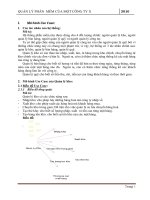
Functions Overview
Busbar
3VTs
27P
59P
59Q
81U
81O
81R
VTS
59G
52
32R
*
50P
*
37P
55
3CTs
51P
37
67P
51Q
49
50BF
CTS
1CT
50G
Motor
CLP
51G
M
67G
87M
FR
1VT
*
3CTs
Protection Functions
ANSI
Protection Functions
Remark
87M
Current differential protection
67P
harmonic control element
Instantaneous current differential protection
Magnetic balance differential protection
Up to 6 stages with independent logic
Voltage control element for each stage
Optional direction element for each stage, including
Phase overcurrent protection
50/51P
Percentage current differential protection with 2nd & 3rd
forward direction, reverse direction and non-direction
Optional definite-time characteristic and inverse-time
characteristic for each stage
Selectable trip purpose or alarm purpose for each stage
Up to 6 stages with independent logic
Optional direction element for each stage, including
forward direction, reverse direction and non-direction
67G
Earth fault protection
Optional measured zero-sequence current or calculated
zero-sequence current
50/51G
Optional definite-time characteristic and inverse-time
characteristic for each stage
PCS-9641S Motor Relay
Selectable trip purpose or alarm purpose for each stage
7
Functions Overview
CLP
Cold load pickup
position
Short resetting is supported
Up to 2 stages with independent logic
Optional direction element for each stage, including
Negative-sequence overcurrent
50/51Q
protection
It can be triggered by on-load signal or circuit breaker
forward direction, reverse direction and non-direction
Optional definite-time characteristic and inverse-time
characteristic for each stage
50/51R
37
49
59P
RMS overcurrent protection
Selectable trip purpose or alarm purpose for each stage
Up to 2 stages with independent logic
Full-current
Thermal overload protection
Overvoltage protection
harmonic
Selectable trip purpose or alarm purpose for each stage
Optional blocking condition, including circuit breaker
position and current criterion
Selectable trip purpose or alarm purpose for each stage
Two stages of thermal overload protection, one stage for
alarm purpose and the other stage for trip purpose
Up to 2 stages with independent logic
Optional definite-time characteristic and inverse-time
characteristic for each stage
Optional phase voltage or phase-to-phase voltage
Optional “1-out-of-3” logic or “3-out-of-3” logic
Selectable trip purpose or alarm purpose for each stage
Positive-sequence overvoltage
One stage of positive-sequence overvoltage protection
protection
Selectable trip purpose or alarm purpose
Negative-sequence overvoltage
Up to 2 stages with independent logic
protection
Selectable trip purpose or alarm purpose for each stage
Up to 2 stages with independent logic
Optional measured zero-sequence voltage or calculated
59Q
Residual overvoltage protection
zero-sequence voltage
8
2nd~11th
RMS value includes
components
Undercurrent protection
59Pos
59G
Selectable trip purpose or alarm purpose for each stage
PCS-9641S Motor Relay
Functions Overview
Up to 2 stages with independent logic
Optional definite-time characteristic and inverse-time
characteristic for each stage
27P
Undervoltage protection
Optional phase voltage or phase-to-phase voltage
Optional “1-out-of-3” logic or “3-out-of-3” logic
Check mode using circuit breaker position and current
criterion
32R
Reverse power protection
37P
Underpower protection
55
Power factor protection
81O
Overfrequency protection
81U
Underfrequency protection
Frequency
rate-of-change
81R
protection
Blocked by instantaneous VT circuit failure
Selectable trip purpose or alarm purpose for each stage
Up to 2 stages with independent logic
Selectable trip purpose or alarm purpose for each stage
Up to 2 stages with independent logic
Selectable trip purpose or alarm purpose for each stage
1 stage logic
Selectable trip purpose or alarm purpose for each stage
Up to 6 stages with independent logic
Voltage control element
Up to 6 stages with independent logic
Voltage control element
Up to 6 stages with independent logic
Voltage control element
Breaker failure protection and re-trip function
Optional current criterion (phase overcurrent element,
zero-sequence overcurrent element, negative-sequence
50BF
Breaker failure protection
overcurrent element)
It can be initiated by current, circuit breaker position or
external binary input
VTS
Voltage transformer supervision
CTS
Current transformer supervision
TCS
Tripping circuit supervision
Two time delays
Control Functions
Circuit breaker & disconnector control (Remote/local)
Measurement Functions
Energy metering (active and reactive energy are calculated in import respectively export direction)
Power (Apparent/Real/Reactive)
PCS-9641S Motor Relay
9
Functions Overview
Power Factor
Frequency
Event Recorder including 1024 disturbance items, 1024 binary events, 1024 supervision events, 256
control logs and 1024 device logs.
Disturbance recorder including 64 disturbance records with waveforms (The file format of
disturbance recorder is compatible with international COMTRADE file.)
Supervision Functions
VT circuit supervision
CT circuit supervision
Trip/Close coil supervision
Self-diagnostic
DC power supply supervision
System frequency supervision
Communication Functions
Up to four 10Base-T/100Base-TX copper Ethernet ports using IEC 61850, DNP3.0 or IEC
60870-5-103 over TCP/IP
Up to four 100Base-FX optical Ethernet ports using IEC 61850, DNP3.0 or IEC 60870-5-103 over
TCP/IP
Two RS-485 serial ports using IEC 60870-5-103 or Modbus
One RS-485 serial port for clock synchronization
Support GOOSE communication module using IEC 61850-8-1 GOOSE
Full compatibility between IEC 61850 Editions 1 and 2
Redundancy protocols PRP and HSR
One front RJ45 port for debugging
Digital Interface
Support IEC 61850 MMS Server via extendable electrical or optical Ethernet port
Support IEC 61850-8-1 GOOSE via extendable electrical or optical Ethernet port
User Interfaces
10
Friendly HMI interface with LCD, easy-to-use keypad aids simple navigation and set-point
PCS-9641S Motor Relay
Functions Overview
adjustment
Push buttons for open/close, switch for selection between local and remote control, and user's login
and logout authority management
4 Programmable operator push-buttons with user-configurable labels
Up to 15/18 (6U, 1/3 × 19" or 6U, 1/2 × 19" chassis) programmable target LEDs with
user-configurable labels
1 RS-485 rear ports for printer
Language switchover—English+ selected language
Auxiliary software—PCS-Studio
Additional Functions
User programmable logic
Fault location
Fault phase selection
System phase sequences rotation function (ABC or ACB)
Clock synchronization
IRIG-B: IRIG-B via RS-485 differential level or TTL level
PPS: Pulse per second (PPS) via RS-485 differential level or binary input
PPM: Pulse per minute (PPM) via RS-485 differential level or binary input
IEEE1588: Clock message based on IEEE1588 via optical fibre interface
SNTP (PTP): Unicast (point-to-point) SNTP mode via Ethernet network
SNTP (BC): Broadcast SNTP mode via Ethernet network
Message (IEC103/Modbus/DNP3.0): Clock messages through IEC103 protocol, Modbus
protocol and DNP3.0 protocol
Cyber security
NERC CIP
IEC 62351
IEC 62443
IEEE 1686
PCS-9641S Motor Relay
11
Functions Overview
12
PCS-9641S Motor Relay
Typical Application
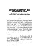
Typical Application
The PCS-9641S relay is a protection, control and monitoring unit for various kinds of motors on solidly
grounded, impedance grounded, Peterson coil grounded and ungrounded system.
PCS-9641S Motor Relay
1VT
Busbar
1CT
M
*
3CTs
*
52
3CTs
*
3VTs
Motor
Figure 1 Typical application of PCS-9641S
PCS-9641S Motor Relay
13
Protection Functions
Protection Functions
Motor Startup Control Function (MSC)
With application of the MSC (Motor Startup Control) module of this device, motor starting process can be
monitored. Moreover, motor restart can be prohibited when the motor is too hot and does not have a
sufficient amount of thermal capacity available.
Current Differential Protection (87M)
If a fault occurs in the protection zone of a motor, current differential protection operates quickly to clear
the fault to avoid the motor from damages or reduce the maintenance cost as low as possible.
Current differential protection includes biased differential element, instantaneous differential element,
magnetic balance differential protection. If motor terminal CT and neutral point CT are applied, biased
differential element and instantaneous differential element should be used. If motor terminal CT and
neutral point CT are applied. If a core-balance CT is equipped for each phase of the motor, or the input
currents of this relay are already differential currents, magnetic balance differential protection should be
used.
Biased differential element is biased characteristic with 2 slopes. Instantaneous differential element is
without biased characteristic and blocking logic, it and can accelerate to operate for motor severe
internal faults. For magnetic balance differential protection, the external differential current inputs should
be connected to motor neutral point side.
Phase Overcurrent Protection (50/51P)
The device can provide six stages of phase overcurrent protection with independent logic. Each stage
can be independently set as definite-time characteristics or inverse-time characteristics. The dropout
characteristics can be set as immediate dropout, definite-time dropout or inverse-time dropout. Users
can choose whether it is blocked by the voltage control element, direction control element, or harmonic
control element, users can also choose whether it is controlled by cold load pickup. The direction control
element can be set as no direction, forward direction and reverse direction. The phase overcurrent
protection picks up when the current exceeds the current threshold value, and operates after a certain
time delay, once the fault disappears, the phase overcurrent protection will dropout.
Earth Fault Overcurrent Protection (50/51G)
The device can provide six stages of earth fault overcurrent protection with independent logic. Each
stage can be independently set as definite-time characteristics or inverse-time characteristics. The
dropout characteristics can be set as immediate dropout, definite-time dropout or inverse-time dropout.
Users can choose whether it is blocked by the direction control element or the harmonic control element,
users can also choose whether it is controlled by cold load pickup. The direction control element can be
set as no direction, forward direction and reverse direction. The zero-sequence current used by earth
fault overcurrent protection can be calculated zero-sequence current or the measured zero-sequence
14
PCS-9641S Motor Relay
Protection Functions
current, it can operate to trip or alarm, and it can be enabled or blocked by the external binary input.
Cold Load Pickup Logic (CLP)
The cold load pickup (CLP) logic which is included within this relay serves to either inhibit the selected
protective elements for an appointed duration, or to raise the settings of the selected protective elements.
Therefore, it allows the protection settings to be set closer to the load profile by automatically increasing
them following circuit energization. The CLP logic thus provides stability, whilst maintaining protection
during starting.
If the CLP logic is operated, the CLP settings are enabled for the overcurrent protection and the zero
sequence overcurrent protection respectively. After the dropout time delay of the CLP logic has elapsed,
the normal protection settings are applied. And if a fast resetting signal is received, the normal protection
settings are applied after the predefine short resetting time delay.
Negative-sequence Overcurrent Protection (50/51Q)
The device can provide two stages of negative-sequence overcurrent protection with independent logic.
Each stage can be independently set as definite-time characteristics or inverse-time characteristics. The
dropout characteristics can be set as immediate dropout, definite-time dropout or inverse-time dropout.
For a double-circuit or a ring network line, the negative-sequence fault current may have different flow
direction. Considering the protection selectivity, the negative-sequence overcurrent protection can be
blocked by the direction control element. Negative-sequence overcurrent current can operate to trip or
alarm, it can be enabled or blocked by the external binary input.
RMS Overcurrent Protection (50/51R)
The device can provide two stages of RMS overcurrent protection with independent logic. When the fault
current with more harmonic components is generated in the system, the amplitude is larger than the
current threshold of RMS overcurrent protection, the RMS overcurrent protection will operate.
The operating characteristics of RMS overcurrent protection is definite-time characteristics. The dropout
characteristics can be set as immediate dropout or definite-time dropout. RMS overcurrent current can
operate to trip or alarm, it can be enabled or blocked by the external binary input.
Undercurrent Protection (37)
The device can provide one stage of undercurrent protection for tripping purpose or alarm purpose. For
different protected equipment, the single-phase criterion or three-phase criterion can be selected. The
position of circuit breaker, the load current also can be taken as the enabling conditions for the
undercurrent protection. The undercurrent protection is with definite-time operation characteristic and
instantaneous dropout characteristic. Undercurrent protection can operate to trip or alarm, it can be
enabled or blocked by the external binary input.
PCS-9641S Motor Relay
15
Protection Functions
Thermal Overload Protection (49)
The device provides two stages of thermal overload protection, one stage for alarm purpose and the
other stage for trip purpose.
The device provides two thermal overload calculation methods: 1) only calculated by current; 2) for the
scenario with oil temperature measurement function, calculate the temperature difference between the
equipment (such as transformer windings) and the oil, and then plus the oil temperature measured by
the sensor, to obtain the final temperature.
Phase Overvoltage Protection (59P)
The device can provide two stages of phase overvoltage protection with independent logic. When a high
voltage occurs in the system, it is greater than the voltage threshold, phase overvoltage protection will
operate to remove the device from the system after a time delay. In addition, the overvoltage protection
also provides the alarm function, prompting the overvoltage of the system, it allows users to find the
cause timely, and preventing further deterioration of the fault. Each stage of phase overvoltage
protection can be independently set as definite-time characteristics or inverse-time characteristics. The
dropout characteristics can be set as immediate dropout and definite-time dropout.
Users can select phase voltage or phase-to-phase voltage for the protection calculation.
“1-out-of-3” or “3-out-of-3” logic can be selected for the protection criterion. (1-out-of-3 means any of
three phase voltages, 3-out-of-3 means all three phase voltages).
Positive-sequence Overvoltage Protection (59Pos)
This device provides one stage of positive-sequence overvoltage protection. If the positive-sequence
voltage is larger than the pre-defined setting, this protection will operate. The positive-sequence
overvoltage protection can operate with a definite-time limit, and the supported dropout characteristics
include instantaneous dropout and definite-time dropout.
Negative-sequence Overvoltage Protection (59Q)
This device provides two stages of negative-sequence overvoltage protection. If the negative-sequence
voltage is larger than the predefined setting, this protection will operate. The negative-sequence
overvoltage protection can operate with a definite-time limit, and the supported dropout characteristics
include instantaneous dropout and definite-time dropout.
Residual Overvoltage Protection (59G)
The device can provide two stages of residual overvoltage protection with independent logic. When the
residual voltage is greater than the voltage threshold, the residual overvoltage protection will operate to
remove the device from the system after a time delay. In addition, the residual overvoltage protection
also provides the alarm function, it prompt that there is an earth fault leading to residual voltage
generation, it allows users to find the cause timely, and preventing further deterioration of the fault. The
16
PCS-9641S Motor Relay
Protection Functions
dropout characteristics of residual overvoltage protection can be set as immediate dropout and
definite-time dropout.
Phase Undervoltage Protection (27P)
The device can provide two stages of phase undervoltage protection with independent logic. When the
voltage drops in the system and it is lower than the voltage threshold, phase undervoltage protection will
operate.
Taking into account that the role of undervoltage protection is to remove the running device from the
system, but in order to prevent that undervoltage protection is always operating when it is not charged,
the breaker closed position check criterion is added, users can choose to detect the breaker position,
current or no-check as the releasing condition for the protection.
In addition, the undervoltage protection also provides the alarm function, prompting the voltage drop of
the system, it allows users to find the cause timely, and preventing further deterioration of the fault. Each
stage of phase undervoltage protection can be independently set as definite-time characteristics or
inverse-time characteristics. The dropout characteristics can be set as instantaneous dropout and
definite-time dropout.
Users can select phase voltage or phase-to-phase voltage for the protection calculation.
“1-out-of-3” or “3-out-of-3” logic can be selected for the protection criterion. (1-out-of-3 means any of
three phase voltages, 3-out-of-3 means all three phase voltages).
Reverse Power Protection (32R)
This device can provide two stages of reverse power protection. If the reverse power is detected and it is
greater than the predefined setting, the reverse power protection will operate. The reverse power
protection is with independent definite time delay characteristic and with definite time delay or
instantaneous dropout characteristic.
Underpower Protection (37P)
This device can provide two stages of underpower protection. If the underpower is detected and it is
greater than the predefined setting, the underpower protection will operate. The underpower protection
is with independent definite time delay characteristic and with definite time delay or instantaneous
dropout characteristic.
Power Factor Protection 55)
This device can provide one stage of power factor protection. In normal operation, synchronous motors
run at unity power factor, but power factor may drop below an acceptable level in case of fault (e.g.: loss
of field to the main exciter, short circuits in the field currents, or excitation system AC power supply loss).
If the power factor is detected and it is lower than the predefined setting, the power factor protection will
operate. The power factor protection is provided with definite time delay characteristic and with definite
time delay or instantaneous dropout characteristic.
PCS-9641S Motor Relay
17
Protection Functions
Overfrequency Protection (81O)
This device can provide six stages of overfrequency protection. If the system frequency is greater than
the predefined setting, this protection will operate for removing some part of active power supplies from
the system. The overfrequency protection is with independent definite time delay characteristic and with
instantaneous dropout characteristic.
Underfrequency Protection (81U)
This device provides six stages of underfrequency protection. If the system frequency is less than the
predefined setting, this protection will operate for shedding some part of loads from the system. The
underfrequency protection is with independent definite time delay characteristic and with instantaneous
dropout characteristic.
Frequency Rate-of-change Protection (81R)
This device can provide six stages of frequency rate-of-change protection. If the system frequency
rate-of-change is greater than the predefined setting, this protection will operate. The frequency
rate-of-change protection is with independent definite time delay characteristic and with instantaneous
dropout characteristic.
Breaker Failure Protection (50BF)
According to the tripping information from the device and the auxiliary information (the current and the
position) of target circuit breaker, breaker failure protection constitutes the criterion to discriminate
whether the target circuit fails to open. If the criterion is confirmed, breaker failure protection will operate
to trip the target circuit breaker with the re-trip time delay, trip it again with the first time delay and trip the
adjacent circuit breakers with the second time delay. As a special backup protection, breaker failure
protection can quickly isolate the fault, reduce the affected range by the fault, keep system stability and
prevent generators, transformers and other primary equipments from seriously damaged.
18
PCS-9641S Motor Relay
Control Functions
Control Functions
Switchgear Control
The switchgear control function is mainly used to realize operation of primary equipments such as circuit
breaker (CB), disconnect switch (DS) and earthing switch (ES). This function can be divided into remote
control and local control according to the control source location. A remote control mainly refers to
remote control commands from substation automation system (SAS) or network control centre (NCC).
However, a control triggered manually from the device LCD, by a terminal contact or by a panel handle is
a local control. The switchgear control function is closely related to interlocking, double point status
(DPS), remote/local control mode switching and tripping statistics.
A control command can realize various control signals such as the CB/DS/ES opening/closing. In order
to ensure the reliability of the control output, a locking circuit is added to each control object. The
operation is strictly in accordance with the selection, check and execution steps, to ensure that the
control operation can be safely and reliably implemented. In addition, the device has a hardware
self-checking and blocking function to prevent hardware damage from mal-operation output.
The switchgear control function can cooperate with functions such as synchronism check and
interlocking criteria calculation to complete the output of the corresponding operation command. It can
realize the normal control output in one bay and the interlocking and programmable logic configuration
between bays.
This device supports the following functional control module:
Module
Description
CSWI
Control of circuit breaker (CB), disconnector switch (DS) or earthing switch (ES)
RMTLOC
Remote or local control mode
XCBR
Synthesis of CB position, three-phase or phase separated
XSWI
Synthesis of DS/ES position
SXCBR/SCSWI
Trip counter of CB/DS/ES
RSYN
Synchronism check for CB closing
CILO
Interlocking logic for CB/DS/ES control
MCSWI
Manual control of CB/DS/ES
CHKPOS
Position verification for switchgear control
Remote/Local Control Mode Switch
When the device is in the remote control mode, the control command may be sent via communication
protocol; when it is in the local control mode, the local operation may be performed on the device LCD or
PCS-9641S Motor Relay
19
Control Functions
panel handle.
The remote/local control mode switch function determines whether the device is in the remote or the
local control permission state through the configuration of terminal contact, function key, or binary signal.
Each control object provides a remote/local input, and the control module determines the current control
authority to be remote or local according to the input value. By default, if the input is not configured, any
control operation is blocked.
Double Point Status
A double point status (DPS), which usually indicates switchgear status, can be derived from 2 ordinary
binary inputs. The unit also supports the DPS synthesis through switchgear opening and closing
positions after jittering processing. The synthetic DPS contains original SOE timestamp. The CB control
function supports phase-separated position inputs and can synthesize these inputs into general position.
Trip Counter
The trip statistics function takes the opening position as input count the trip times. For CB, this device
supports phase-separated and general trip statistics. The tripping statistics function is triggered by DPS
change. The statistics result is stored in non-volatile memory for power-off holding.
Use the clear command from the menu in local LCD to reset the trip statistics.
20
PCS-9641S Motor Relay
Monitoring Functions
Monitoring Functions
VT Circuit Supervision (VTS)
VT circuit supervision can detect failure of single-phase, two-phase and three-phase on protection VT.
Under normal condition, the device continuously supervises input voltage from VT, VT circuit failure
signal will be activated if residual voltage exceeds the threshold value, or negative voltage exceeds the
threshold value or positive-sequence voltage is lower than the threshold value. If the specific current
protection (such as breaker failure protection) operates to pick up, the time delay count-down of VT
supervision alarm shall be paused until the protection returns to normal state.
VT (secondary circuit) MCB auxiliary contact can be connected to the binary input circuit of the device as
a binary signal. If the MCB has been opened, the device will consider that the VT circuit is in a bad
condition and issue an alarm without a time delay. If the auxiliary contact is not connected to the device,
VT circuit supervision will be issued with time delay as mentioned in previous paragraph.
CT Circuit Supervision (CTS)
The purpose of the CT circuit supervision is to detect any abnormality on CT secondary circuit. When CT
secondary circuit is abnormal, the current acquired by the device is not accurate, which will affect
protection functions related to the current. Therefore, it is necessary to monitor the CT abnormal
condition. When CT abnormality is detected, the device shall issue an alarm signal and block the
relevant protection functions.
Under normal conditions, CT secondary signal is continuously supervised by detecting the residual
current and voltage. If residual current is larger than a settable setting, whereas residual voltage is less
than a settable setting, and any phase current is less than 0.04In, CT circuit failure is considered.
PCS-9641S Motor Relay
21
Hardware
Hardware
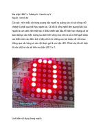
Front Panel
1
1
3
6
6
2
4
4
7
2
5
7
5
3
1.
Front-panel status indication and control of switches
2.
Easy-to-use keypad aids simple navigation and set-point adjustment
3.
Push buttons for open/close, switch for selection between local and remote control, and user's login
and logout authority management
4.
Programmable operator push-buttons with user-configurable labels
5.
RJ45 Interface
6.
Up to 18 (6U, 1/2 × 19")/15 (6U, 1/3 × 19") programmable target LEDs with user-configurable labels
7.
Target reset
22
PCS-9641S Motor Relay
Hardware
Rear Panel
3
4
3
1
5
6
2
4
1
2
5
6
Figure 2 Typical rear view of this device (pin-ferrule-terminal modules)
PCS-9641S Motor Relay
23