PCS 9671s x datasheet EN overseas general x r1 11
Bạn đang xem bản rút gọn của tài liệu. Xem và tải ngay bản đầy đủ của tài liệu tại đây (1.81 MB, 41 trang )
About This Document
About This Document
The manual describes the protection, measurement and supervision functions with the information of
relevant hardware for PCS-9671S Transformer Relay.
Copyright © 2020 NR. All rights reserved.
NR, the NR logo are either registered trademarks or trademarks of NR Electric Co., Ltd. No NR
trademarks may be used without written permission. NR products appearing in this document may be
covered by P.R. China and foreign patents. NR Electric Co., Ltd. reserves all rights and benefits afforded
under P.R. China and international copyright and patent laws in its products, including but not limited to
software, firmware and documentation. NR Engineering Co., Ltd. is licensed to use this document as
well as all intellectual property rights owned or held by NR Electric Co., Ltd, including but not limited to
copyright, rights in inventions, patents, know-how, trade secrets, trademarks and trade names, service
marks, design rights, database rights and rights in data, utility models, domain names and all similar
rights.
The information in this document is provided for informational use only and does not constitute a legal
contract between NR and any person or entity unless otherwise specified. Information in this document
is subject to change without prior notice.
To the extent required the products described herein meet applicable IEC and IEEE standards, but no
such assurance is given with respect to local codes and ordinances because they vary greatly.
Although every reasonable effort is made to present current and accurate information, this document
does not purport to cover all details or variations in equipment nor provide for every possible contingency
to be met in connection with installation, operation, or maintenance. Should further information be
desired or should particular problems arise which are not covered sufficiently for your purposes, please
do not hesitate to contact us.
PCS-9671S Transformer Relay
1
Document Revision History
Document Revision History
PN: ZL_PCS-9671S_X_DataSheet_EN_Overseas General_X
Current version: R1.11
Corresponding Version
Release Date
Software
R1.00
R1.00
2019-10-18
Form the original manual.
R1.10
R1.00
2019-12-04
Update of technical data.
Update of technical data.
Improved some description of protection functions
Added PWR plug-in module NR6311A.
Added CPU plug-in module NR6106AH.
Added CPU plug-in module NR6106AP.
Added BIBO plug-in module NR6661A.
R1.11
2
Description of change
Document
R1.11
2020-06-08
PCS-9671S Transformer Relay
Overview
Overview
PCS-9671S has been designed specifically for the protection of various type power transformers,
including two-winding transformers, three-winding transformers (up to 3 branches), auto-transformers in
any voltage level. PCS-9671S provides the main protection elements, such as: current differential
protection and restricted earth fault protection. With its modular structure, flexibility and the powerful
PCS-Studio engineering tool, PCS-9671S offers future-oriented system solutions with high investment
security and low operating costs.
PCS-9671S Transformer Relay
3
Highlights
Highlights
Unified software and hardware platform, comprehensive power grid solutions of protection, control,
measurement and monitoring, easy to use and maintain.
High reliability and redundancy design for drive systems of the sampling circuit and the output circuit
ensure that overall reliability of the device is high. Real-time sampling based on dual AD can mutually
check and detect the potential abnormality in the sampling circuit in time. The control power supply of
the output relay is independent with the control circuit of trigger signals, which can prevent from
undesired operation caused by the abnormality of drive circuit of output relays.
Various function modules can satisfy various situations according to the different requirements of
users. Flexible and universal logic programming, user-defined configuration of BI/BOs, buttons and
LEDs and powerful analog programming are supported.
Modularized hardware design makes the device be easily upgraded or repaired by a qualified service
person. It can be mixed with different I/O modules, with online self-check and monitoring function,
and the device can be restored from abnormal operation only need to replace a single abnormal
module.
Support memory check and error correction function, ensure high reliability and safety.
Support the internet communication protocol of native PRP/HSR and RSTP.
Fully compatible with IEC 61850 edition 1 & edition 2, support MMS service, IEC 62351
communication service, GOOSE communication in station level & process level, SV communication
with multi-sampling rate.
Full comply with cyber security standards, including IEC62443, IEC62351, IEEE1686, NERC-CIP,
support role based access control (RBAC), security audit, security encryption communication and
security tool, improve the cyber security capability of devices.
Powerful COMTRADE fault and disturbance recording function is supported. The whole recording
time is automatically configurable by the fault duration, which is convenient to fault analysis and
replay. The recording sample rate is up to 9.6kHz.
Settable secondary rated current (1A/5A) and settable voltage threshold of binary input
Support large size LCD, control and multifunction button
Support flush mounting, semi-flush mounting, surface mounting, wall mounting and other mounting
methods.
Cross screw IO, CT/VT terminals can support AWG12 specification connector and 4mm2 lead
Protection class of front side is up to IP54
PCS-Studio engineering tool is the application software on the user's PC for the interface with PCS S
series devices providing all the related functionality. It ranges from device configuration to full
4
PCS-9671S Transformer Relay
Highlights
substation design of bay integration.
Support IEEE1588, IRIG-B clock synchronization
Support actual system phase sequence, either ABC or ACB, incorrect connection of actual phase
sequence can automatically be verified and relevant protection functions can be blocked.
Equipped with high-speed large capacity output relay, its operation speed is less than 1ms and its
break capacity is up to 10A. The real-time supervision for output drive circuit can detect the
abnormality in advance.
Support setup up to 40 users and allow each user to own different password and access authority.
PCS-9671S Transformer Relay
5
Features
Features
The tripping output contacts can be configured by tripping matrix, which is flexible, convenient and
suitable to any mode of tripping.
Multiple inrush current blocking options are provided. Self-adaptive inrush current blocking criterion
can ensure the relay fast operation for transformer energized on to a slight fault, meanwhile it will
avoid the unwanted operation in the case of the energization inrush current caused by energizing
transformer with no load, the recovery inrush current caused by cutting off the transformer external
fault, and the sympathetic inrush current.
Biased DPFC differential protection is regardless of load current and is sensitive to small internal fault
current within the transformer. Its anti CT saturation performance is also strong.
6
PCS-9671S Transformer Relay
Functions Overview
Functions Overview
Side 1
*
3CT
52
87T
1CT
64REF
64REF
64REF
50/51P
50/51P
50/51P
50/51G
50/51G
50/51G
*
*
1CT
1CT
*
52
52
3CT
*
3CT
*
Side 3
Side 2
Protection Functions
ANSI
Protection Functions
Remark
Biased differential protection with three slopes
Biased DPFC differential protection
Unrestrained instantaneous differential protection
Optional inrush current distinguished principles: harmonic
criterion or waveform distortion
87T
Transformer differential protection
Optional harmonic blocking modes: self-adaptive 1Pblk1P
mode, 2PBlk3P mode, 1Pblk3P mode
Overexcitation detection: fifth harmonic or third harmonic
criterion
64REF
50/51P
Restricted earth-fault protection
Optional transfer methods: △→Y or Y→△
Independent CT saturation criterion
Differential CT circuit failure supervision
CT transient characteristic difference detection
CT saturation detection based on 2nd and 3rd harmonics
2 stages with independent logic by default for each side
Optional definite-time characteristic and inverse-time
Phase overcurrent protection
PCS-9671S Transformer Relay
characteristic for each stage
Trip purpose or alarm purpose for each stage
Harmonic control element for each stage
7
Functions Overview
2 stages with independent logic by default for each side
Optional measured zero-sequence current or calculated
zero-sequence current
50/51G
Earth fault protection
Optional definite-time characteristic and inverse-time
characteristic for each stage
Selectable trip purpose or alarm purpose for each stage
Harmonic control element for each stage
Measurement and Metering Functions
Positive sequence currents, zero sequence currents and phase angles
Supervision Functions
CT circuit failure Supervision (CTS)
Self diagnostic
Powerful faults recording (max. buffer for 10,000 sampled points at 4.8 or 9.6 kHz)
Event Recorder including 1024 disturbance records, 1024 binary events, 1024 supervision events,
256 control logs and 1024 device logs.
Disturbance recorder including 64 disturbance records with waveforms (The file format of
disturbance recorder is compatible with international COMTRADE file.)
Single line diagram representation in display
Communication Functions
Support of various protocols
Modbus, DNP3.0, IEC 60870-5-103, IEC 61850 Ed.1 & Ed.2, IEC 61850 MMS Server, IEC
61850-8-1 GOOSE, IEC 61850-9-2LE SV, IEC 62439 Parallel Redundancy Protocol (PRP), IEC
62439 High-availability Seamless Ring (HSR) Redundancy Protocol, IEEE 802.1w Rapid Spanning
Tree Protocol (RSTP).
Up to four 10Base-T/100Base-TX copper Ethernet ports
Up to four 100Base-FX optical Ethernet ports
Two RS-485 serial ports for communication or printer
One RS-485/TTL serial port for clock synchronization
Two RJ45 debugging ports (front and rear)
User Interfaces
Friendly HMI interface with LCD, easy-to-use keypad aids simple navigation and set-point
8
PCS-9671S Transformer Relay
Functions Overview
adjustment
Push buttons for open/close, switch for selection between local and remote control, and user's login
and logout authority management
4 Programmable operator pushbuttons with user-configurable labels
Up to 15 programmable target LEDs with user-configurable labels
1 RS-232 or RS-485 rear ports for printer
Language switchover—English+ selected language
Configuration tool—PCS-Studio
Additional Functions
User programmable logic
Switching system phase sequences function (ABC or ACB)
Clock synchronization
IRIG-B: IRIG-B via RS-485 differential level, TTL level or optical fibre interface
PPS: Pulse per second (PPS) via RS-485 differential level or binary input
PPM: Pulse per minute (PPM) via RS-485 differential level or binary input
IEEE 1588: Clock message based on IEEE 1588 via optical fibre interface
SNTP (PTP): Unicast (point-to-point) SNTP mode via Ethernet network
SNTP (BC): Broadcast SNTP mode via Ethernet network
Message (IEC103/Modbus/DNP3.0): Clock messages through IEC103 protocol, Modbus
protocol and DNP3.0 protocol
Cyber security
NERC CIP
IEC 62351
IEC 62443
IEEE 1686
PCS-9671S Transformer Relay
9
Typical Application
Typical Application
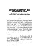
PCS-9671S can be applied for a two-winding transformer, three-winding transformer or auto-transformer
in any voltage level. PCS-9671S provides the main protection elements, such as: current differential
protection and restricted earth fault protection. Ancillary functions of fault diagnostic, disturbance records,
event records and communication function are integrated in the device.
PCS-9671S is adaptive to the following 2/3-winding transformers.
Figure 1 Two-winding transformer
Figure 2 Three-winding transformer
10
PCS-9671S Transformer Relay
Protection Functions
Protection Functions
Transformer Current Differential Protection (87T)
In power system, the power transformer is one of most valuable and expensive equipment. If a fault
occurs in the protection zone of a transformer, current differential protection operates quickly to clear the
fault to avoid the transformer from damages or reduce the maintenance cost as low as possible.
Transformer differential protection can be provided with up to 3 sets of three-phase current inputs, and
can be used for 2-winding, 3-winding transformer and auto-transformer. There are 12 vector groups
available for 2-winding transformer and 3-winding transformer.
Transformer differential protection includes biased differential element, instantaneous differential
element, DPFC biased differential element. Biased differential element is biased characteristic with three
slopes Instantaneous differential element is without biased characteristic and blocking logic and can
accelerate to operate for transformer's severe internal faults. DPFC biased differential element
calculated by current variation has high sensitivity to inter-turn faults and high-impedance fault under
heavy load. Three differential elements mentioned above work coordinately to form the high-speed
current differential protection with high sensitivity.
Restricted Earth Fault Protection (64REF)
Restricted earth fault protection (REF) is meant to protect a single winding of a power transformer, and
the protected winding must be earthed. In the case of delta windings, the winding must be earthed by an
earthing transformer, which must be electrically placed between the winding and the current
transformers. REF can be applied to protection of two-winding transformer, three-winding transformer or
auto-transformer.
REF is a kind of differential protection, so it calculates differential current and restrained current. The
differential current is a vector difference of the neutral current (i.e., current flowing in the neutral
conductor) and the residual current from the lines. For internal faults, this difference is equal to the total
earth fault current. REF operates on the fault current only, and is not dependent on eventual load
currents. This makes REF a very sensitive protection.
The difference between current differential protection and REF is that the first one is based on adjusted
phase current balance and the latter is based on balance of calculated residual current and residual
current from neutral CT.
Each side of transformer can be equipped with one set of REF, i.e., for a three-winding transformer, up to
three groups of REF can be equipped. REF is not affected by inrush current and the tap of transformer.
CT transient characteristic detection function based on the ratio of residual current to positive current is
adopted to eliminate the influence of difference of transient characteristic to REF.
PCS-9671S Transformer Relay
11
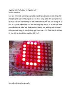
*
Protection Functions
I_H
Side 2
*
*
Side 1
3I0Cal'_H
Magnitude compensation
I'_HNP
I_HNP
REF at side 1
*
Figure 3 Application for two-winding transformer with one CB at one side
Branch 1 of side 1
*
*
*
I_H1
Side 2
I_H2
*
*
3I0Cal'_H2
*
3I0Cal'_H1
Branch 2 of side 1
Magnitude
compensation
I_HNP
REF at side 1
Magnitude
compensation
*
Magnitude
compensation
I'_HNP
Figure 4 Application for two-winding transformer with two CBs at one side
12
PCS-9671S Transformer Relay
Protection Functions
Side 1
*
*
*
I_H
I_M
*
3I0Cal'_H
*
CW side
*
Side 2
3I0Cal'_M
I_CW
Side 3
Magnitude
compensation
REF at side 1
*
Magnitude
compensation
Magnitude
compensation
I'_CW
Figure 5 Application for auto-transformer
The protection function can be provided with up to 4 sets of three-phase current inputs and 1 neutral
point current input, and in auto-transformer applications, it can be provided with up to 2 sets of ����������������������������������������������������������������������������������������������������������������������������������������������������������������������������������������������������������������������������������������������������������������������������������������������������������������������������������������������������������������������������������������������������������������������������������������������������������������������������������������������������������������������������������������������������������������������������������������������������������������������������������������������������������������������������������������������������������������������������������������������������������������������������������������������������������������������������������������������������������������������������������������������������������������������������������������������������������������������������������������������������������������������������������������������������������������������������������������������������������������������������������������������������������������������������������������������������������������������������������������������������������������������������������������������������������������������������������������������������������������������������������������������������������������������������������������������������������������������������������������������������������������������������������������������������������������������������������������������������������������������������������������������������������������������������������������������������������������������������������������������������������������������������������������������������������������������������������������������������������������������������������������������������������������������������������������������������������������������������������������������������������������������������������������������������������������������������������������������������������������������������������������������������������������������������������������������������������������������������������������������������������������������������������������������������������������������������������������������������������������������������������������������������������������������������������������������������������������������������������������������������������������������������������������������������������������������������������������������������������������������������������������������������������������������������������������������������������������������������������������������������������������������������������������������������������������������������������������������������������������������������������������������������������������������������������������������������������������������������������������������������������������������������������������������������������������������������������������������������������������������������������������������������������������������������������������������������������������������������������������������������������������������������������������������������������������������������������������������������������������������������������������������������������������������������������������������������������������������������������������������������������������������������������������������������������������������������������������������������������������������������������������������������������������������������������������������������������������������������������������������������������������������������������������������������������������������������������������������������������������������������������������������������������������������������������������������������������������������������������������������������������������������������������������������������������������������������������������������������������������������������������������������������������������������������������������������������������������������������������������������������������������
190.5
259
233.5
9.5
168.4
202.4
185.4
Semi-flush Mounting
20
PCS-9671S Transformer Relay
Installation
Case size (mm)
6U, 1/3 × 19”
H3
H4
D4
D5
W3
W4
W5
190.5
259
82.5
160.5
168.4
202.4
185.4
PCS-9671S Transformer Relay
21
Installation
Surface mounting
Case size (mm)
6U, 1/3 × 19”
22
D6
D7
H5
W6
4~10
243—D6
254.5
151.4
PCS-9671S Transformer Relay
Installation
Wall Mounting
PCS-9671S Transformer Relay
23
Installation
Case size (mm)
D8
W7
W8
H6
H7
6U, 1/3 × 19''
292
219.4
187.4
320
280
Note: The wall mounting method needs special mounting accessory for wall support.
24
PCS-9671S Transformer Relay
Installation
Rack Mounting
Cut-out
PCS-9671S Transformer Relay
25
Installation
26
Single 6U, 1/3 × 19''
PCS-9671S Transformer Relay
Installation
Dual 6U, 1/3 × 19'', side-by-side
PCS-9671S Transformer Relay
27
Technical Data
Technical Data
Electrical Specifications
AC Current Input
Phase rotation
ABC or ACB
Nominal frequency (fn)
50Hz, 60Hz
Rated current (In)
1A/5A (settable)
Linear to
0.05In~40In
Thermal withstand
-continuously
4In
-for 10s
30In
-for 1s
100In
-for half a cycle
250In
Burden
<0.05VA/phase @1A, <0.25VA/phase @5A
Number
Up to 12 AC current inputs
Power Supply
IEC 61000-4-11:2017
Standard
IEC 61000-4-29:2000
100Vac/110Vac/
115Vac/120Vac/
110Vdc/125Vdc/
Rated voltage
24Vdc/48Vdc
127Vac/220Vac/
220Vdc/250Vdc
230Vac/240Vac/
250Vac
Permissible voltage range
18~72Vdc
Permissible AC ripple voltage
Max. 15% of the nominal auxiliary voltage
Burden
Max. 15W (default hardware configuration)
28
Quiescent condition
88~300Vdc
80~275Vac
PCS-9671S Transformer Relay
Technical Data
Additional for each
energized SFP socket
Max. 0.35W
Quiescent condition
Max. 1W
0.004W @24Vdc
Additional for each plug-in
binary input (BI) module
0.008W @48Vdc
Additional for each contact
0.015W @110Vdc
0.32W @220Vdc
0.41W @250Vdc
Additional for each plug-in
binary output (BO)
module
Quiescent condition
Max. 0.1W
Additional for each relay while
operating
Max. 0.44W
Binary Input: Settable pickup voltage and dropout voltage
Rated voltage
110Vdc
125Vdc
220Vdc
250Vdc
Rated current drain
0.73mA
0.83mA
1.47mA
1.67mA
On value (default set)
69.3~132Vdc
78.75~160Vdc
138.6~264Vdc
157.5~300Vdc
Off value (default set)
<55Vdc
<62.5Vdc
<110Vdc
<125Vdc
Maximum permissible voltage
300Vdc
Withstand voltage
2000Vac, 2800Vdc (1min)
Number
Up to 34 (ring ferrule), 41 (pin ferrule) binary inputs
Binary Input: Settable pickup voltage and dropout voltage
Rated voltage
110Vac
220Vac
Rated current drain
0.73mA
1.47mA
On value (default set)
69.3~132Vac
138.6~264Vac
Off value (default set)
<55Vac
<110Vac
Maximum permissible voltage
300Vac
Withstand voltage
2000Vac, 2800Vdc (1min)
PCS-9671S Transformer Relay
29
Technical Data
Number
Up to 34 (ring ferrule), 41 (pin ferrule) binary inputs
Binary Input: Settable pickup voltage and dropout voltage
Rated voltage
24Vdc
48Vdc
Rated current drain
0.16mA
0.32mA
On value (default set)
15.12~28.8Vdc
30.24~57.6Vdc
Off value (default set)
<12Vdc
<24Vdc
Maximum permissible voltage
300Vdc
Withstand voltage
2000Vac, 2800Vdc (1min)
Number
Up to 34 (ring ferrule), 41 (pin ferrule) binary inputs
Binary Output: Tripping/signaling contact
Output mode
Potential free contact
Max. system voltage
250Vac, 300Vdc
Continuous carry
10A
Pickup time (Typical value)
<5ms
Dropout time (Resistive load)
<6ms
0.5A@48Vdc
0.35A@110Vdc
Breaking capacity (L/R=40ms)
0.30A@125Vdc
0.20A@220Vdc
0.15A@250Vdc
0.5A@48Vdc
0.35A@110Vdc
Cyclic Capacity (2.5 cycle/second,
0.30A@125Vdc
L/R=40ms)
0.20A@220Vdc
0.15A@250Vdc
Short duration current
30
30A@3s
PCS-9671S Transformer Relay