SIMULATION AND SPEED CONTROL OF INDUCTION MOTOR DRIVES
Bạn đang xem bản rút gọn của tài liệu. Xem và tải ngay bản đầy đủ của tài liệu tại đây (4.34 MB, 76 trang )
SIMULATION AND SPEED CONTROL OF
INDUCTION MOTOR DRIVES
A THESIS SUBMITTED IN PARTIAL FULFILMENT
OF THE REQUIREMENTS FOR THE DEGREE OF
Bachelor of Technology
In
ELECTRICAL ENGINEERING
By
AMITPAL SINGH I.S. BHATIA (108EE054)
VINIT KUMAR GUPTA (108EE059)
SOURAV ANAND SETHI (108EE077)
Under the guidance and supervision of
PROF. KANUNGO BARADA MOHANTY
Dept. of Electrical Engineering
NIT, Rourkela
Department of Electrical Engineering
National Institute of Technology
Rourkela - 769008
May 2012
Department of Electrical Engineering
National Institute of Technology
Rourkela - 769008
May 2012
CERTIFICATE
This is to certify that the thesis entitled, “Simulation and Speed Control of Induction Motor
Drives” submitted by AMITPAL SINGH I. S. BHATIA (108EE054), VINIT KUMAR GUPTA
(108EE059) and SOURAV ANAND SETHI (108EE077) in partial fulfilment of the requirements
for the award of Bachelor of Technology Degree in Electrical Engineering at the National
Institute of Technology, Rourkela (Deemed University) is an authentic work carried out by
them under my supervision and guidance.
To the best of my knowledge, the matter embodied in the thesis has not been submitted to
any other University / Institute for the award of any Degree or Diploma.
Professor KANUNGO BARADA MOHANTY
Department of Electrical Engineering
National Institute of Technology
Rourkela – 769008
I|Page
Department of Electrical Engineering
National Institute of Technology
Rourkela - 769008
May 2012
ACKNOWNLEDGEMENT
We would like to articulate our deep gratitude to our project guide Prof. Kanungo Barada
Mohanty, who has always been our motivation for carrying out the project. His constant
inspiration and effort made this project work a great success. We are thankful to him for his
contributions in completing this project work. An assemblage of this nature could never
have been attempted without reference to and inspiration from the works of others whose
details are mentioned in reference section. We acknowledge our indebtedness to all of
them. Last but not the least we would like to thank our parents and the Almighty.
AMITPAL SINGH I. S. BHATIA (108EE054)
VINIT KUMAR GUPTA (108EE059)
SOURAV ANAND SETHI (108EE077)
Dept. of Electrical Engineering
National Institute of Technology
Rourkela – 769008
II | P a g e
Department of Electrical Engineering
National Institute of Technology
Rourkela – 769008
May 2012
ABSTRACT
Induction motors are the most widely used electrical motors due to their reliability, low cost
and robustness. However, induction motors do not inherently have the capability of variable
speed operation. Due to this reason, earlier dc motors were applied in most of the electrical
drives. But the recent developments in speed control methods of the induction motor have led
to their large scale use in almost all electrical drives.
Out of the several methods of speed control of an induction such as pole changing, frequency
variation, variable rotor resistance, variable stator voltage, constant V/f control, slip recovery
method etc., the closed loop constant V/f speed control method is most widely used. In this
method, the V/f ratio is kept constant which in turn maintains the magnetizing flux constant
so that the maximum torque remains unchanged. Thus, the motor is completely utilized in
this method.
During starting of an induction motor, the stator resistance and the motor inductance (both
rotor and stator) must be kept low to reduce the steady state time and also to reduce the jerks
during starting. On the other hand, higher value of rotor resistance leads to lesser jerks while
having no effect on the steady state time.
The vector control analysis of an induction motor allows the decoupled analysis where the
torque and the flux components can be independently controlled (just as in dc motor). This
makes the analysis easier than the per phase equivalent circuit.
III | P a g e
CONTENTS
CERTIFICATE.................................................................................................................................. I
ACKNOWNLEDGEMENT ................................................................................................................ II
ABSTRACT................................................................................................................................... III
LIST OF TABLES ........................................................................................................................... VI
LIST OF FIGURES.......................................................................................................................... VI
LIST OF SYMBOLS ........................................................................................................................ IX
CHAPTERS
1. INTRODUCTION ........................................................................................................................ 1
2. LITERATURE REVIEW ................................................................................................................ 2
2.1 Three phase induction motor and their Torque-Speed analysis .................................................. 2
3. TRANSIENTS DURING STARTING OF A 3- INDUCTION MOTOR .................................................. 5
3.1 Low stator inductance (~0.05 mH)................................................................................................ 6
3.2 Medium stator inductance (~0.7 mH)......................................................................................... 10
3.3 High stator inductance (~2 mH) .................................................................................................. 14
3.4 Low Rotor Resistance (~0.1 ) ................................................................................................... 18
3.5 High Rotor Resistance (~0.5 ) ................................................................................................... 22
3.6 Low Stator Resistance (~0.16 )................................................................................................. 26
3.7 High Stator Resistance (~0.8 ) .................................................................................................. 30
4. ANALYSIS OF VARIOUS METHODS FOR SPEED CONTROL OF IM ................................................ 35
4.1 Variable Rotor Resistance ........................................................................................................... 35
4.2 Variable Stator Voltage ............................................................................................................... 36
4.3 Constant V/f Control ................................................................................................................... 37
4.3.1 Closed Loop V/f speed control method ............................................................................... 38
4.3.2 Open Loop V/f speed control method using PI controller ................................................... 42
4.3.3 Closed Loop V/f speed control method using PI controller ................................................. 44
4.4 Vector Control Method ............................................................................................................... 47
4.4.1 d-q Equivalent Circuit ........................................................................................................... 47
4.4.2 Axes Transformation............................................................................................................ 48
5. CONCLUSIONS ........................................................................................................................ 54
IV | P a g e
REFERENCES .............................................................................................................................. 55
APPENDICES .............................................................................................................................. 56
Appendix 1: MATLAB Code for Speed Control of 3- Induction motor using Variable Rotor
Resistance ......................................................................................................................................... 56
Appendix 2: MATLAB Code for Speed Control of 3- Induction motor using Variable Stator Voltage
.......................................................................................................................................................... 58
Appendix 3: MATLAB Code for Speed Control of 3- Induction motor using Constant V/f control . 60
Appendix 4: MATLAB Code for Closed Loop Speed Control of 3- Induction motor using Constant
V/f ..................................................................................................................................................... 62
Appendix 5: MATLAB Code to observe the variations in q-axis and d-axis stator currents with
change in stator voltage for a 3- induction motor.......................................................................... 65
V|Page
LIST OF TABLES
Table 1: Machine details used in MATLAB codes execution for variable rotor resistance,
variable stator voltage and constant V/f control
Table 2: Motor rating and parameters used in MATLAB code execution for Vector control
method
LIST OF FIGURES
Figure 1.1: Block diagram of an electrical drive
Figure 2.1: Per phase equivalent circuit of a 3- induction motor
Figure 2.2: Per phase approximate equivalent circuit of a 3- induction motor
Figure 3.1: SIMULINK model of a 3- Induction motor
Figure 3.2: Parameters of 3- induction motors (Low stator impedance)
Figure 3.3: Rotor Speed Vs Time graph for machine parameters as in Figure 3.2
Figure 3.4: Torque Vs Time graph for machine parameters as in Figure 3.2
Figure 3.5: Stator Current Vs Time graph for machine parameters as in Fig 3.2
Figure 3.6: Rotor Current Vs Time graph for machine parameters as in Fig 3.2
Figure 3.7: Torque-Speed Characteristics for machine parameters as in Fig 3.2
Figure 3.8: Parameters of 3- induction motors (Medium stator inductance)
Figure 3.9: Rotor Speed Vs Time graph for machine parameters as in Figure 3.8
Figure 3.10: Torque Vs Time graph for machine parameters as in Figure 3.8
Figure 3.11: Stator Current Vs Time graph for machine parameters as in Fig 3.8
Figure 3.12: Rotor Current Vs Time graph for machine parameters as in Fig 3.8
Figure 3.13: Torque-Speed Characteristics for machine parameters as in Fig 3.8
Figure 3.14: Parameters of 3- induction motors (High stator inductance)
Figure 3.15: Rotor Speed Vs Time graph for machine parameters as in Fig 3.14
Figure 3.16: Torque Vs Time graph for machine parameters as in Figure 3.14
Figure 3.17:Stator Current Vs Time graph for machine parameters as in Fig 3.14
VI | P a g e
Figure 3.18:Rotor Current Vs Time graph for machine parameters as in Fig 3.14
Figure 3.19:Torque-Speed Characteristics for machine parameters as in Fig 3.14
Figure 3.20: Parameters of 3- induction motors (Low Rotor Resistance)
Figure 3.21: Rotor Speed Vs Time graph for machine parameters as in Fig 3.20
Figure 3.22: Torque Vs Time graph for machine parameters as in Figure 3.20
Figure 3.23:Stator Current Vs Time graph for machine parameters as in Fig 3.20
Figure 3.24:Rotor Current Vs Time graph for machine parameters as in Fig 3.20
Figure 3.25:Torque-Speed Characteristics for machine parameters as in Fig 3.20
Figure 3.26: Parameters of 3- induction motors (High Rotor Resistance)
Figure 3.27: Rotor Speed Vs Time graph for machine parameters as in Fig 3.26
Figure 3.28: Torque Vs Time graph for machine parameters as in Figure 3.26
Figure 3.29:Stator Current Vs Time graph for machine parameters as in Fig 3.26
Figure 3.30:Rotor Current Vs Time graph for machine parameters as in Fig 3.26
Figure 3.31:Torque-Speed Characteristics for machine parameters as in Fig 3.26
Figure 3.32: Parameters of 3- induction motors (Low Stator Resistance)
Figure 3.33: Rotor Speed Vs Time graph for machine parameters as in Fig 3.32
Figure 3.34: Torque Vs Time graph for machine parameters as in Figure 3.32
Figure 3.35:Stator Current Vs Time graph for machine parameters as in Fig 3.32
Figure 3.36:Rotor Current Vs Time graph for machine parameters as in Fig 3.32
Figure 3.37:Torque-Speed Characteristics for machine parameters as in Fig 3.32
Figure 3.38: Parameters of 3- induction motors (High Stator Resistance)
Figure 3.39: Rotor Speed Vs Time graph for machine parameters as in Fig 3.38
Figure 3.40: Torque Vs Time graph for machine parameters as in Figure 3.38
Figure 3.41:Stator Current Vs Time graph for machine parameters as in Fig 3.38
Figure 3.42:Rotor Current Vs Time graph for machine parameters as in Fig 3.38
Figure 3.43:Torque-Speed Characteristics for machine parameters as in Fig 3.38
Figure 4.1: Torque-Speed characteristics of a 3-IM with variable rotor resistance
VII | P a g e
Figure 4.2: Torque-Speed characteristics of a 3-IM with variable stator voltage
Figure 4.3: Torque-Speed characteristics of a 3-IM with constant V/f ratio
Figure 4.4: Block diagram for closed loop V/f control on a 3-IM
Figure 4.5: Input Data (Machine details) for Closed loop Constant V/f Speed Control Method
Figure 4.6 Torque-Speed Characteristics with Starting Load Torque 1.5 Nm and Reference
Speed 500 rpm
Figure 4.7 Torque-Speed Characteristics with Starting Load Torque 1 Nm and Reference
Speed 1200 rpm
Figure 4.8 Torque-Speed Characteristics with Starting Load Torque 0 Nm and Reference
Speed 1500 rpm
Figure 4.9: SIMULINK block of open loop constant V/f speed control using PI controller
Figure 4.10: Variation of Stator current of a 3-in case of open loop PI control for constant
V/f control method
Figure 4.11: Variation of DC bus voltage of a 3-in case of open loop PI control for constant
V/f control method
Figure 4.12: Variation of Torque of a 3-in case of open loop PI control for constant V/f
control method
Figure 4.13: Variation of Rotor Speed of a 3-in case of open loop PI control for constant
V/f control method
Figure 4.14: SIMULINK block of close loop constant V/f speed control using PI controller
Figure 4.15: Variation of Stator current of a 3-in case of closed loop PI control for constant
V/f control method
Figure 4.16: Variation of DC Bus Voltage of a 3-in case of closed loop PI control for
constant V/f control method
Figure 4.17: Variation of Torque of a 3-in case of closed loop PI control for constant V/f
control method
Figure 4.18: Variation of Rotor Speed of a 3-in case of closed loop PI control for constant
V/f control method
Figure 4.19: Angular relationships between reference axes
Figure 4.20: Variation of q-axis stator current with change in stator voltage
Figure 4.21: Variation of d-axis stator current with change in stator voltage
VIII | P a g e
LIST OF SYMBOLS
IM
Induction Motor
Rs
Stator Resistance
Rr
Rotor Resistance
Rr’
Rotor Resistance Referred to Stator side
Xs
Stator Reactance
Xr
Rotor Reactance
Xr’
Rotor Reactance Referred to Stator side
Xm
Leakage Inductance
I1
Stator Current
I2
Rotor Current
I2’
Rotor Current Referred to Stator side
Im
Magnetizing Current
V0
Stator Voltage
s
Slip
ωs
Synchronous Speed
ωm
Rotor Speed (Machine Speed)
Ωs
Average Synchronous Speed (in RPM)
f
Supply Frequency
p
No. of Poles
Pg
Air-gap Power
Pcu
Copper loss in the machine
Pm
Mechanical Power output of the machine
T
Torque Developed by the motor
sm
Slip at maximum torque
Tmax
Maximum Torque
Vd
DC Link Voltage
ωref
Reference Speed
IX | P a g e
ωsl
Slip Speed
ωf
Rotor Speed at Frequency f
Yd
Space Vector in d-axis
Yq
Space Vector in q-axis
Ya
Space Vector of a-phase
Yb
Space Vector of b-phase
Yc
Space Vector of c-phase
Vqs
q-axis Stator Voltage with stationary frame
Vds
d-axis Stator Voltage with stationary frame
Iqs
q-axis Stator Current with stationary frame
Ids
d-axis Stator Current with stationary frame
Iqr
q-axis Rotor Current with stationary frame
Idr
d-axis Rotor Current with stationary frame
λds
d-axis Stator flux with stationary frame
λqs
q-axis Stator flux with stationary frame
λdr
d-axis Rotor flux with stationary frame
λqr
q-axis Rotor flux with stationary frame
λs
q-axis Rotor flux with stationary frame
Ls
Stator Self-Inductance
Lr
Rotor Self-Inductance
Lm
Stator Mutual-Inductance
Is’
Complex Conjugate of Stator Current
Pi
Instantaneous Active Power
Qi
Instantaneous Reactive Power
X|Page
Simulation and Speed Control of Induction Motor Drives 2012
CHAPTER I
INTRODUCTION
Be it domestic application or industry, motion control is required everywhere. The systems
that are employed for this purpose are called drives. Such a system, if makes use of electric
motors is known as an electrical drive. In electrical drives, use of various sensors and control
algorithms is done to control the speed of the motor using suitable speed control methods.
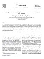
The basic block diagram of an electrical drive is shown below:
SOURCE
POWER
MODULATOR
MOTOR
CONTROL
UNIT
LOAD
SENSING
UNIT
INPUT
COMMAND
Figure 1.1: Block diagram of an electrical drive
Earlier only dc motors were employed for drives requiring variable speeds due to ease of
their speed control methods. The conventional methods of speed control of an induction
motor were either too expensive or too inefficient thus restricting their application to only
constant speed drives. However, modern trends and development of speed control methods of
an induction motor have increased the use of induction motors in electrical drives
extensively.
In this paper, we have studied the various methods of speed control of a 3- induction motor
and compared them using their Torque-Speed characteristics. Also the transients during the
starting of a 3- induction motor were studied using MATLAB Simulink and the effects of
various parameters such as rotor and stator resistances and inductances were analysed. Also
different control algorithms such as P, PI and PID control were studied by simulating them in
MATLAB Simulink and were compared.
1|Page
Simulation and Speed Control of Induction Motor Drives 2012
CHAPTER 2
LITERATURE REVIEW
2.1 Three phase induction motor and their Torque-Speed analysis
Based on the construction of the rotor, a 3-induction motor can be categorized into two
types:
i.
ii.
Squirrel Cage Induction Motor
Wound Rotor or Slip Ring Induction Motor
The stator of both types of motors consists of a three phase balanced distributed winding with
each phase mechanically separated in space by 120 degrees from the other two phase
windings. This gives rise to a rotating magnetic field when current flows through the stator.
In squirrel cage IM, the rotor consists of longitudinal conductor bars which are shorted at
ends by circular conducting rings. Whereas, the wound rotor IM has a 3-balanced
distributed winding even on the rotor side with as many number of poles as in the stator
winding.
Considering the three phases to be balanced, the analysis of a 3-induction motor can be
done by analysing only one of the phases. The per phase equivalent circuit of an induction
motor is shown below:
Figure 2.1: Per phase equivalent circuit of a 3-induction motor
R2 and X2 are the stator referred values of rotor resistance R1 and rotor reactance X1. Slip is
defined by
s = (s – m)/ s
(2.1)
where, ωm and ωs are rotor and synchronous speeds, respectively.
2|Page
Simulation and Speed Control of Induction Motor Drives 2012
s = 120f/p rpm
Further,
(2.2)
Where f and p are supply frequency and number of poles, respectively.
Since, stator impedance drop is generally negligible compared to terminal voltage V, the
equivalent circuit can be simplified to that shown below:
Figure 2.2: Per phase approximate equivalent circuit of a 3- induction motor
Rotor current
(
)
(2.3)
Power transferred to rotor (or air-gap power)
(2.4)
Rotor copper loss is
(2.5)
Electrical power converted into mechanical power
(2.6)
3|Page
Simulation and Speed Control of Induction Motor Drives 2012
Torque developed by motor
(2.7)
Thus,
(2.8)
Substituting the value of I2 into the above equation, we get,
(
(2.9)
)
Differentiating T with respect to s and equating to zero gives the slip for maximum torque
(2.10)
√
Substituting Sm in T gives the value of maximum torque, thus
[
√(
)]
(2.11)
4|Page
Simulation and Speed Control of Induction Motor Drives 2012
CHAPTER 3
TRANSIENTS DURING STARTING OF
A 3- INDUCTION MOTOR
A model of a 3- induction motor was setup in MATLAB SIMULINK and the rotor and
stator currents, speed, electromagnetic torque and the Torque-Speed characteristics were
observed with different values of rotor and stator resistances and impedances.
The SIMULINK model is shown below.
Figure 3.1: SIMULINK model of a 3- Induction motor
The different machine details followed by their corresponding outcomes are shown in this
chapter.
It should be noted that all the simulations were made for Zero Load Torque. However,
the inertia and friction were taken into consideration.
5|Page
Simulation and Speed Control of Induction Motor Drives 2012
3.1 Low stator inductance (~0.05 mH)
Figure 3.2: Parameters of 3- induction motors (Low stator impedance)
6|Page
Simulation and Speed Control of Induction Motor Drives 2012
Figure 3.3: Rotor Speed Vs Time graph for machine parameters as in Figure 3.2
Figure 3.4: Torque Vs Time graph for machine parameters as in Figure 3.2
7|Page
Simulation and Speed Control of Induction Motor Drives 2012
Figure 3.5: Stator Current Vs Time graph for machine parameters as in Fig 3.2
Figure 3.6: Rotor Current Vs Time graph for machine parameters as in Fig 3.2
8|Page
Simulation and Speed Control of Induction Motor Drives 2012
Figure 3.7: Torque-Speed Characteristics for machine parameters as in Fig 3.2
9|Page
Simulation and Speed Control of Induction Motor Drives 2012
3.2 Medium stator inductance (~0.7 mH)
Figure 3.8: Parameters of 3- induction motors (Medium stator inductance)
10 | P a g e
Simulation and Speed Control of Induction Motor Drives 2012
Figure 3.9: Rotor Speed Vs Time graph for machine parameters as in Figure 3.8
Figure 3.10: Torque Vs Time graph for machine parameters as in Figure 3.8
11 | P a g e
Simulation and Speed Control of Induction Motor Drives 2012
Figure 3.11: Stator Current Vs Time graph for machine parameters as in Fig 3.8
Figure 3.12: Rotor Current Vs Time graph for machine parameters as in Fig 3.8
12 | P a g e
Simulation and Speed Control of Induction Motor Drives 2012
Figure 3.13: Torque-Speed Characteristics for machine parameters as in Fig 3.8
13 | P a g e
Simulation and Speed Control of Induction Motor Drives 2012
3.3 High stator inductance (~2 mH)
Figure 3.14: Parameters of 3- induction motors (High stator inductance)
14 | P a g e