Thiết kế nguồn động lực và hệ thống truyền lực xe máy điện thể thao
Bạn đang xem bản rút gọn của tài liệu. Xem và tải ngay bản đầy đủ của tài liệu tại đây (3.42 MB, 42 trang )
HCMC UNIVERSITY OF TECHNOLOGY AND EDUCATION
FACULTY OF VEHICLE AND ENERGY ENGINEERING
CAPSTONE PROJECT
A DESIGN OF PRIME MOVER AND
TRANSMISSION SYSTEM FOR ELECTRIC
SPORT BIKE
Advisor: MEng. Huynh Thinh
Student:
Tran Ngoc Thuc
Nguyen My Canh
IDS:
15145383
15145194
Contents
1. The status and vehicle development trend.
1.1. Status.
1.2. Vehicle development trend.
2. Missions of the project.
2.1. Calculating and choosing prime mover.
2.2. Designing powertrain.
2.3. Evaluating simulation in Matlab Simulink.
3. Process
3.1. Developing initial specifications.
3.2. Calculating primer mover parameters and gear ratio.
3.3. Simulating in Simulink.
3.4. Simulation results evaluation.
3.5. Conclusions and suggestions.
2
1. The status and vehicle development trend.
1.1.Status.
Nowadays, most of vehicles use internal combustion engine and fossil fuel.
They exhaust a lot of emissions into environment such as CO, NOx …
3
1.2. Vehicle development trend.
The trend of development is using electric motor instead of internal combustion engine.
4
2. Missions of project
2.1. Calculating and choosing prime mover
Defining user’s scenario:
• Flexibility moving in the city.
• High performance in suburban.
Design requirements:
• Maximum velocity > 60km/h.
• 0 to 50km/h acceleration under 7s.
• Good hill climbing ability.
2.1. Calculating and choosing prime mover
Based on User’s scenario and Design
requirements, the prime mover
parameters will be calculated and an
available electric motor will be
chosen
6
2.2.Designing powertrain.
When a prime mover is chosen, the type of powertrain will be considered.
Transmission type
Belt
Chain drive
Hub motor
7
2.2.Designing powertrain.
The powertrain specifications will be calculated
8
2.3. Evaluating simulation in Matlab Simulink.
Some system simulations will be used to validate performance of the vehicle with chosen
prime mover and powertrain
9
3. THE PROCESS.
1. Developing
initial
specifications
2. Calculating
prime mover
parameters and
gear ratio
4. Simulation
results
evaluation
3. Simulating in
Simulink
5. Conclusions
and
suggestions
10
3.1. Developing initial specifications
Available parameters.
-
Curb weight of the vehicle is 100 kg.
The weight of vehicle with rider is 165 kg.
The weight of vehicle with rider and passenger is 230 kg.
Normal tire force at front is 44% total weight
- Normal tire force at rear is
-
11
3.1. Developing initial specifications
Determining vehicle center of gravity
- The wheel base of the vehicle: p=1348.18 (mm) .
- The high of the center of gravity: h (mm) .
- The horizontal distance between the center and the
rear wheel axle: b (mm) .
b=
- We have:
, then we choose h=0.4p
h= 0.4p = 0.4* 1348.18= 539.27 (mm)
- Coordinate of the vehicle with 165kg ( 503.3 ; 689.2).
- Coordinate of the vehicle with 230kg ( 463.6 ; 754.4).
12
3.2.
Calculating prime mover parameters and gear ratio
Calculating power demanded.
Based on vehicle power equilibrium equation:
+ : Tractive power at drive wheel(W)
+ : Power of rolling resistance (W).
+ : Power of slope resistance(W).
+ : Power of aerodynamic resistance (W).
+ : Power of inertia resistance(W).
we have transformed the equation and put
in matlab to calculate the required power
within time domain
13
3.2. Calculating prime mover parameters and gear ratio
Velocity (km/h)
Calculating power demanded
Power (W)
Because of the low efficiency of the motor at low speed range, so the required
power of the motor is multiplied by factor “1.5” P= 2885*1.5= 4327.5 (W).
14
3.2. Calculating prime mover parameters and gear ratio
Choosing electric motor.
- Brushless DC motor
(BLDC motor) type is
chosen.
15
3.2. Calculating prime mover parameters and gear ratio
Design gear ratio
From vehicle equilibrium equation
16
3.2. Calculating prime mover parameters and gear ratio
Velocity (m/s)
Design gear ratio
Time (s)
17
3.2. Calculating prime mover parameters and gear ratio
Design gear ratio.
Time
5
5.5
6
6.5
7
6
10.64
11.65
12.66
13.65
14.63
6.2
11.00
12.05
13.09
14.11
15.12
6.4
11.36
12.45
13.52
14.57
15.61
6.8
11.73
12.84
13.95
15.03
16.10
7
12.09
13.24
14.37
15.49
16.59
7.2
12.45
13.63
14.80
15.95
17.08
7.4
12.81
14.03
15.22
16.40
17.56
7.6
13.17
14.42
15.65
16.86
18.05
7.8
13.53
14.81
16.07
17.31
18.53
8
13.89
15.21
16.50
17.77
19.01
Gear ratio
18
3.2. Calculate to choose electronic motor and transmission ratio.
Design chain drive .
One-level chain drive is used because motor torque characteristic is
similar to vehicle ideal characteristic.
Choose the ratio is =6.
• The number of drive teeth is .
• The number of driven teeth is .
• Because the velocity is 4489rpm, the chain step is chosen
• The diameter of drive sprocket is
• The diameter of driven sprocket is
• The chain maximum tension is
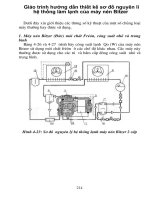
3.3. Simulating in Simulink
General simulating model.
Motor
Chain
Drive
Vehicle
Body
Tire
20
3.3. Simulating in Simulink
Lookup Table block.
The input value is speed.
The output value is the corresponding
torque.
21
3.3. Simulating in Simulink
Clusters of blocks.
Cluster of motor parameters.
22
3.3. Simulating in Simulink
Clusters of blocks.
Cluster of powertrain and sensors.
23
3.3. Simulating in Simulink
Clusters of blocks.
Cluster of vehicle body and tire.
24
3.3. Simulating in Simulink
Clusters of blocks.
Clusters of driving cycles and PID controller.
25