Tài liệu KRONE - White paper - TrueNET - AirES_Elec_WP - 2002 pptx
Bạn đang xem bản rút gọn của tài liệu. Xem và tải ngay bản đầy đủ của tài liệu tại đây (561.17 KB, 7 trang )
has developed yet
another industry
leading technology. The AirES product
range of cables are a true innovation in
structured cabling. In most evolutionary
processes the gain in one attribute
often sacrifices another. With the AirES
evolution all attributes, both physical
and electrical, are improved to provide
a "Win Win" situation for both the
installer and customer.
This white paper will focus on the electrical attribute
advantages of AirES. Herein, we will discuss the
revolutionary development of the technology and the
byproduct effects on any and all electrical parameters.
A full glossary of terms is included for further
understanding.
Background
To fully understand the benefits of the TrueNet AirES
solution, one must first understand the fundamentals
of cabling and the hurdles overcome by this product.
Good Dielectric Constant is key in producing high
quality data communications cable. The lower the
Dielectric Constant of the insulation material, the
better the resistance to breakdown when an electrical
field is applied. Air, with a Dielectric Constant of 1.0,
is the best of all insulators and is the basis by which
others are measured. KRONE has understood this and
has been using air as an insulator in our connectivity
products for many years.
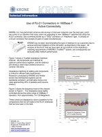
Below is an example of different materials and their
Dielectric Constants. Water, Glass and Air were
added to the list to give a better understanding as to
what constitutes a good Dielectric Constant. It may
be relevant to note the Dielectric Constant of Glass
is higher than FEP insulation. This results in fiber
optic cables having a lower Nominal Velocity of
Propagation (NVP) than UTP copper cables.
The NVP is the speed a signal propagates through a
cable expressed as a percentage of the speed of light
in a vacuum (300million m/sec) and given the value of 1.
The NVP of a data communications cable can be
directly calculated from the dielectric constant of the
insulating material and differs with change in frequency.
The speed of the signal over multi-pair data commu-
nications cable is critical for high speed networks.
This can be attributed to two main factors.
1. The speed at which the signal is traveling (NVP).
2. The total length of the cable pair, which allows for
twist rate.
Both of these parameters combined are measured as
Propagation Delay or the time delay between the
sent and received signal.
One of the byproducts of using FEP as an insulation
material over FRPE is an increase in the NVP due to
its lower Dielectric Constant. The typical NVP of
SAME
design cables, using FEP as an insulator over
TrueNet
™
AirES
™
Technology
Electrical Characteristics of the Evolution
KKRROONNEE
™
78.5
4.3
3.6
2.5
2.1
1.0
WATER
POLYIMIDE-GLASS
PVC
FLAME RETARDANT
POLYETHYLENE
FEP (TEFLON)
AIR
DIELECTRIC CONSTANT
FRPE, would typically increase up to 4% in NVP, there-
fore making FEP a faster insulating material.
Below is a table of typical NVP values for different
cable categories:
Note the Type 1 cables of old had an advantage in
NVP over current UTP designs, coming in at 78%.
Type 1 cable is able to achieve much higher NVP val-
ues through the foaming of the insulation materials.
This introduces air pockets within the dielectric. Air
has a much better Dielectric Constant than FEP, thus
increasing the signal speed. Type 1 cable was also
shielded or PIMF (Pairs In Metal Foil) cable which
allowed for crush resistance. This may also occur on
unshielded foamed insulation materials.
The AirES Innovation:
KRONE’s challenge was to develop a cabling insula-
tion using air as an insulator, increasing NVP to the
same levels as that of Type 1 cable, and at the same
time, having a high level of crush resistance for UTP
applications. The use of foamed insulation in UTP
cables can prove to have an adverse effect on the
integrity of the structure, as it leaves the cable sus-
ceptible to crushing. By placing solid ribs around the
entire conductor, crush resistance has exceeded the
requirements of UL444 by more than 4X.
In the KRONE AirES designed cables, AIR combined
with traditional FEP has been introduced as an insu-
lating material. The result is a NVP that parallels Type 1
cable and at the same time remains crush resistant.
*Does not include twist rate effects.
The total effect of using air combined with FEP as an
insulation material is a 31% reduction in Dielectric
Loss. Here’s how it works.
The equation for working out the Dielectric Loss due
to insulation type where
E
is the Dielectric constant
of the insulation material and Fp is the power factor
of the material is:
Or the Dielectric Constant
of FEP
Or the Dielectric Constant
of FEP and Air in airES
Or the Power Factor of FEP
Or the Power Factor of FEP
and Air in airES
Within the original equation both the Dielectric
Constant and the Power Factor of the material are
reduced with the introduction of air.
CABLE TYPE INSULATION MATERICAL TRANSMISSION TYPE TYPICAL NVP*
TYPE 1 FOAMED POLYETHYLENE TOKEN RING 78%
CAT 3 PVC 10BaseT 53%
CAT 4 ECTFE 100BaseT4 63%
CAT 5 FRPE 100BaseTX 66%
CAT 5 FEP 100BaseTX 70%
CAT 5E FRPE 1000BaseT 66%
CAT 5E FEP 1000BaseT 70%
CAT 6 FRPE 1000BaseT 66%
CAT 6 FEP 1000BaseT 70%
CABLE TYPE INSULATION MATERICAL TRANSMISSION TYPE TYPICAL NVP*
AIRES
™
CAT 5E FEP AND AIR 1000BaseT 78%
AIRES
™
CAT 6 FEP AND AIR 1000BaseT 78%
AirES AIR pockets as
an insulation material.
The effect is a 31% reduction in Loss due to
Dielectric. The obvious benefit to a reduced dielectric
loss is a direct improvement to signal loss, i.e.
stronger signal strength. This allows for a reduction
in copper conductor size without the sacrifice of
performance on Attenuation, which has a greater
impact on the mechanical attributes.
Through the introduction of air pockets between
the FEP and copper conductor the total Dielectric
Constant is reduced. The capacitive effects are
decreased*. This is then brought back to the nominal
100Ω by reducing the OD of the insulation. The total
effect is faster pair transmission on a smaller pair
footprint.
The effect of the faster NVP is low Propagation Delay.
Currently the allowable Delay for Cat5e and Cat 6
is ≤570ns between transmitter and receiver. As
mentioned before, the Propagation Delay is also a
function of the length of the pair, including the twist.
The greater the twist rate the longer the pair. The TrueNet
AirES cable is able to reduce the amount of twist
needed for each pair as well as increasing the NVP.
*Impedance = the square root of the inductance
(conductor effects) divided by the capacitance
(insulation effects), or
By reducing the capacitance, impedance is higher.
This can be corrected by reducing insulation size,
thus the AirES invention.
This results in a Propagation Delay of ≤475ns, 17%
better than the standard. Allowing for a more equal
time delivery on Gigabit Ethernet. This makes the
work of the electronics easier and gives more of a
buffer for error free transmission.
Delay Skew:
Even more critical than the Propagation Delay is the
Delay Skew, the difference in time each signal takes
to arrive on all 4 pairs. For 10/100BaseT transmission
this is not as critical since only 2 of the 4 pairs are
being used for transmission. Delay Skew becomes
important only when we migrate to 1000BaseT
(Gigabit) tranmission, as we are now transmitting on
all 4 pairs at the same time. For optimal performance
the signals should arrive at the receiver as close to
the same time as possible. The standards allow for
up to 45nS in delay between the fastest and slowest
pairs. There are other schools of thought that support
a reduction to <25nS. The AirES cable, due to its fast
NVP and reduced need for twist lay variation oper-
ates at a <20nS Delay Skew. This is unparalleled by
any other Category 5e and 6 UTP cable on the mar-
ket today. To achieve the Near End Cross Talk (NEXT)
performance, all other manufacturers must vary the
twist lays greatly, increasing Delay Skew.
As illustrated below, it is variation in twist lays which
allow for reduced NEXT within cable. Often to
increase NEXT performance, Delay Skew must be
compromised, robbing “Peter to pay Paul”, so to
speak. With the AirES innovation of introducing Air
as an insulator the Cross Talk is naturally reduced
without increasing twist lay variation. As a function of
better insulation through AIR reducing the dielectric
constant and capacitive coupling, there is less
Crosstalk between pairs due to reduced noise. In
other words, noise doesn’t travel well through air!
100Ω
32% less cross
sectional area
100Ω @
17% REDUCED
DISTANCE
Reproduced with permission of Fluke Networks
Reproduced with permission of Fluke Networks
Reproduced with permission of Fluke Networks
The total effect of the cable construction is a smaller
cable with better all around electrical performance. In
the example below the old version (industry standard
design) on the left is compared with the new AirES
design. Once jacketed, the effect of having significantly
smaller primary conductors carries through to the final
overall cable OD. The result is a 28% reduction in
cross sectional area for Cat 5e and a 32% reduction for
Cat 6. This translates to greatly increased fill rate
capacity and easier installation.
Note: For more information regarding the mechanical
advantages of AirES please see our "Mechanical
Attributes" white paper.
Quite often in our industry we struggle to understand
the relationship between all parameters testing on
UTP cables. To break it down into simple terms we
are interested in Signal to Noise Ratios (ACR). How
strong is the signal when it reaches the receiver and
how much noise is on the line. Once again, typically
increasing the performance of one reduces the per-
formance of the other or the size of the cable must
be increased, but not with AirES. The Noise (Cross
Talk) has been reduced, not by increased twist rate,
but through the introduction of AIR. This allows the
twist rates in each pair to be less, resulting in a
shorter length on each pair. Ultimately decreasing the
amount of Attenuation (Insertion Loss), thus supplying
stronger signal strength.
For more information regarding AirES and all other
KRONE products please contact the following:
Customer Support
1-800-775-KRONE (5766)
Sales Engineer near you
/>Author Bio
Tim Takala is the Director of Support Technologies
for KRONE Inc. Prior to joining the US team in 2000,
he was the Laboratory and Technical Manager for
Asia/Pac, KRONE Australia. Mr. Takala was instrumental
in the development and implementation of the
technical methodologies behind KRONE’s TrueNet
™
System and its warranty program, Mr. Takala holds
an Industrial Engineering degree from the Sydney
Institute of Technology.
0.17"
0.20"
Glossary of Terms – Reproduced with
Permission of Fluke Networks
Dielectric Constant:
The property of a dielectric which determines the
amount of electrostatic energy that can be stored by
the material when a given voltage is applied to it.
Also called permativity.
Length and NVP:
Length is defined as the physical or sheath length of
the cable. It should correspond to the length derived
from the length markings commonly found on
the outside jacket of the cable. Physical length is in
contrast to electrical or helical length, which is the
length of the copper conductors. Physical length will
always be slightly less than electrical length, due to
the twisting of the conductors.
To measure length, a test set first measures delay,
then uses the cable's nominal velocity of propagation
to calculate length. Nominal Velocity of Propagation
(NVP) refers to the inherent speed of signal travel
relative to the speed of light in a vacuum (designated
as a lower case c). NVP is expressed as a percentage
of c, for example, 72%, or 0.72c. All structured
wiring cables will have NVP values in the range of
0.6c to 0.9c. Similarly, if you know the physical length
and the delay of a cable you can calculate the NVP.
In most instances, length is derived from the shortest
electrical length pair in the cable. Because of delay
skew, the length of the four pairs often appears slightly
different. This is normal and no cause for concern with
the exception of significant (over 10%) variances.
Results Interpretation
The main concern when measuring length is that
there is not a lot of cable in any segment. For hori-
zontal structured cabling this means 100 meters. This
is because applications have been designed to sup-
port a maximum signal propagation delay, and if the
link is too long, this delay could be exceeded.
Occasionally installers may leave excess cable in the
ceiling or wall in anticipation of future needs. While
this is okay if it is considered part of the overall run,
tightly coiling excess cable can lead to undesirable
performance degradation due to additional return
loss and near end crosstalk.
Troubleshooting Recommendations
One of the most common reasons for failing length
on a test is that the NVP is set incorrectly. If you are
not careful and use the preset cable type it may not
match the NVP of the cable under test. In this case,
you can have an NVP difference of 10% or more,
which translates directly into a length error. In the
event the length is only slightly too long, check the
NVP and cable type.
Assuming the NVP is correct, another cause of excess
length is extra cabling looped in the ceiling or walls.
Does the link in question meet the anticipated plan?
For example, in the case of an airline hanger or
warehouse, a remote station may be forced to be
over 100 meters from the wiring closet. If this has been
planned for, and the intended application supports the
excess length, then the link may fail structured wiring
standards but still be approved for the application.
Some field testers allow customized autotests to be
configured that permit variances from standard TIA
and ISO/CENELEC requirements. Such autotests are
useful because they verify the installation meets
requirements while allowing for planned variances.
Propagation Delay:
Propagation delay, or delay, is a measure of the time
required for a signal to propagate from one end of
the circuit to the other. Delay is measured in
nanoseconds (nS). Typical delay for category 5e UTP
is a bit less than 5 nS per meter (worst case allowed
is 5.7 nS/m). A 100 meter cable might have delay as
shown below.
Delay is the principle reason for a length limitation in
LAN cabling. In many networking applications, such
as those employing CSMA/CD, there is a maximum
delay that can be supported without losing control
of communications.
Nominal Velocity of Propagation (NVP) on the other
hand, is different. NVP refers to the inherent speed
of signal travel relative to the speed of light in a vac-
uum (designated as a lower case c). NVP is expressed
as a percentage of c, for example, 72%, or 0.72c. All
structured wiring cables will have NVP values in the
range of 0.6c to 0.9c.