- Trang chủ >>
- Khoa Học Tự Nhiên >>
- Vật lý
Tài liệu Physics exercises_solution: Chapter 26 ppt
Bạn đang xem bản rút gọn của tài liệu. Xem và tải ngay bản đầy đủ của tài liệu tại đây (418.85 KB, 38 trang )
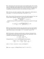
26.1: a)
.3.12
20
1
32
1
1
eq
R
b)
.A5.19
3.12
V240
eq
R
V
I
c)
.A12
20
V240
;A5.7
32
V240
2032
R
V
I
R
V
I
26.2:
.
11
21
21
eq
1
21
21
1
21
eq
RR
RR
R
RR
RR
RR
R
.and
2
21
1
2eq1
21
2
1eq
R
RR
R
RRR
RR
R
RR
26.3: For resistors in series, the currents are the same and the voltages add. a) true.
b) false. c)
.
2
RIP
i same, R different so P different; false. d) true. e) V = IR. I
same, R different; false. f) Potential drops as move through each resistor in the
direction of the current; false. g) Potential drops as move through each resistor in the
direction of the current, so
;
c
VV
b
false. h) true.
26.4: a) False, current divides at junction a.
b) True by charge conservation.
c) True.
R
IVV
1
so,
21
d) False.
.so,but,.
212121
PPIIVVIVP
e) False.
.,Since.
1212
2
PPRRIVP
R
V
f) True. Potential is independent of path.
g) True. Charges lose potential energy (as heat) in
.
1
R
h) False. See answer to (g).
i) False. They are at the same potential.
26.5: a)
.8.0
8.4
1
6.1
1
4.2
1
1
eq
R
b)
;A5.17)6.1()V28(;A67.11)4.2()V28(
6.16.14.24.2
RεIRεI
.A83.5)8.4()V28(
8.48.4
RεI
c)
.A35)8.0()V28(
totaltotal
RεI
d) When in parallel, all resistors have the same potential difference over them, so here
all have V = 28 V.
e)
)6.1()A5.17(;W327)4.2()A67.11(
2
6.1
2
6.1
2
4.2
2
4.2
RIPRIP
W.163)8.4()A83.5(;W490
2
8.4
2
8.4
RIP
f) For resistors in parallel, the most power is dissipated through the resistor with the
least resistance since
constant.with,
2
2
V
R
V
RIP
26.6: a)
.8.88.46.14.2
eq
i
RR
b) The current in each resistor is the same and is
.A18.3
8.8
V28
eq
R
ε
I
c) The current through the battery equals the current of (b), 3.18 A.
d)
)6.1)(A18.3(;V64.7)4.2)(A18.3(
6.16.14.24.2
IRVIRV
.V3.15)8.4)(A18.3(;V09.5
8.48.4
IRV
e)
)6.1()A18.3(;W3.24)4.2()A18.3(
2
6.1
2
6.1
2
4.2
2
4.2
RIPRIP
.W5.48)8.4()A18.3(;W2.16
2
8.4
2
8.4
RIP
f) For resistors in series, the most power is dissipated by the resistor with the greatest
resistance since
.constantwith
2
IRIP
26.7: a)
.V274)000,15)(W0.5(
2
PRV
R
V
P
b)
.W6.1
000,9
)V120(
22
R
V
P
26.8:
00.5
00.4
1
0.12
1
00.6
1
00.3
1
11
eq
R
.
A0.12)00.5()V00.6(
totaltotal
RεI
A;00.9)0.12(
412
12
;A00.3)0.12(
412
4
412
II
A00.4)0.12(
63
3
;A00.8)0.12(
63
6
63
II
.
26.9:
00.3
00.700.5
1
00.100.3
1
1
eq
R
.
A0.16)00.3()V0.48(
totaltotal
RεI
.
A0.12)0.16(
124
12
;A00.4)0.16(
124
4
3175
IIII
.
26.10: a) The three resistors
432
and, RRR
are in parallel, so:
99.0
50.4
1
50.1
1
20.8
1111
1
1
432
234
RRR
R
49.499.050.3
2341eq
RRR
.
b)
.V69.4)50.3()A34.1(A34.1
49.4
V0.6
111
eq
1
RIV
R
ε
I
,A162.0
20.8
33.1
V33.1)99.0()A34.1(
2
22341
234
234
V
R
V
IRIV
R
R
.A296.0
50.4
V33.1
andA887.0
50.1
V33.1
4
4
3
3
234234
R
V
I
R
V
I
RR
26.11: Using the same circuit as in Problem 27.10, with all resistances the same:
00.6
50.4
3
50.4
111
1
1
432
12341eq
RRR
RRRR
.
a)
.A500.0
3
1
A,50.1
00.6
V00.9
1432
eq
1
IIII
R
ε
I
b)
.W125.1
9
1
,W13.10)50.4()A50.1(
1432
2
1
2
11
PPPPRIP
c) If there is a break at
,
4
R
then the equivalent resistance increases:
.75.6
50.4
2
50.4
11
1
1
32
1231eq
RR
RRRR
And so:
.A667.0
2
1
A,33.1
75.6
V00.9
132
eq
1
III
R
ε
I
d)
.W99.1
4
1
,W96.7)50.4()A33.1(
132
2
1
2
11
PPPRIP
e) So
32
and RR
are brighter than before, while
1
R
is fainter. The amount of current
flow is all that determines the power output of these bulbs since their resistances are
equal.
26.12: From Ohm’s law, the voltage drop across the 6.00
resistor is V = IR =
V.24.0)A)(6.0000.4(
The voltage drop across the 8.00
resistor is the same,
since these two resistors are wired in parallel. The current through the 8.00
resistor is
then
.A00.300.8V0.24 RVI
The current through the 25.0
resistor is the
sum of these two currents: 7.00 A. The voltage drop across the 25.0
resistor is V = IR
= (7.00 A)( 25.0
) = 175 V, and total voltage drop across the top branch of the circuit is
175 + 24.0 = 199 V, which is also the voltage drop across the 20.0
resistor. The
current through the 20.0
resistor is then
.A95.920V199 RVI
26.13: Current through 2.00-
resistor is 6.00 A. Current through 1.00-
resistor also
is
6.00 A and the voltage is 6.00 V. Voltage across the 6.00-
resistor is 12.0 V + 6.0 V =
18.0 V. Current through the 6.00-
resistor is
A.00.3)00.6()V0.18(
The battery
voltage is 18.0 V.
26.14: a) The filaments must be connected such that the current can flow through each
separately, and also through both in parallel, yielding three possible current flows. The
parallel situation always has less resistance than any of the individual members, so it will
give the highest power output of 180 W, while the other two must give power outputs of
60 W and
120 W.
.120
W120
)V120(
W120and,240
W60
)V120(
W60
2
2
2
22
1
1
2
R
R
V
R
R
V
Check for parallel:
.W180
80
)V120(
)(
)V120(
)(
2
1
120
1
240
1
2
1
11
2
21
RR
V
P
b) If
1
R
burns out, the 120 W setting stays the same, the 60 W setting does not work
and the 180 W setting goes to 120 W: brightnesses of zero, medium and medium.
c) If
2
R
burns out, the 60 W setting stays the same, the 120 W setting does not work,
and the 180 W setting is now 60 W: brightnesses of low, zero and low.
26.15: a)
.A100.0
)800400(
V120
R
ε
I
b)
)800()A100.0(;W0.4)400()A100.0(
22
800
22
400
RIPRIP
.W12W8W4W0.8
total
P
c) When in parallel, the equivalent resistance becomes:
.A449.0
267
V120
267
800
1
400
1
eq
total
1
eq
R
ε
IR
.A150.0)A449.0(
800400
400
;A30.0)A449.0(
800400
800
800400
II
d)
W18)800()A15.0(;W36)400()A30.0(
22
800
22
400
RIPRIP
.W54W18W36
total
P
e) The 800
resistor is brighter when the resistors are in series, and the 400
is
brighter when in parallel. The greatest total light output is when they are in parallel.
26.16: a)
.72
W200
)V120(
;240
W60
)V120(
22
W200
22
W60
P
V
R
P
V
R
.A769.0
)72240(
V240
ε
W200W60
R
II
b)
W.6.42)72()A769.0(;W142)240()A769.0(
22
W200
22
W60
RIPRIP
c) The 60 W bulb burns out quickly because the power it delivers (142 W) is 2.4 times
its rated value.
26.17:
;0)0.50.50.20(V0.30 I
I = 1.00 A
For the
-0.20
resistor thermal energy is generated at the rate
.W0.20
2
RIP
givesand TmcQPtQ
s1001.1
W0.20
)C0.40()KkgJ4190()kg100.0(
3
P
Tmc
t
26.18: a)
1
2
11
RIP
00.5)A2(W20
11
2
RR
10and
1
R
in parallel:
A1
A)2()5()10(
10
10
I
I
So
212
and.A50.0 RRI
are in parallel, so
)5()A2()A50.0(
2
R
0.20
2
R
b)
V0.10)5)(A2(
1
Vε
c) From (a):
A00.1,A500.0
102
II
d)
(given)W0.20
1
P
W00.5)20()A50.0(
2
2
2
22
RiP
W0.10)10()A0.1(
2
10
2
1010
RiP
W0.35W10W5W20
Resist
P
W35.0V)(10.0A)(3.50
Battery
εIP
energy.ofon conservati with theagreeswhich
Battery,Resist
PP
26.19: a)
.A00.2A00.4A00.6
R
I
b) Using a Kirchhoff loop around the outside of the circuit:
.00.50)A00.2()00.3()A00.6(V0.28 RR
c) Using a counterclockwise loop in the bottom half of the circuit:
.V0.420)00.6()A00.4()00.3()A00.6( εε
d) If the circuit is broken at point x, then the current in the 28 V battery is:
.A50.3
5.003.00
V0.28
R
ε
I
26.20: From the given currents in the diagram, the current through the middle branch
of the circuit must be 1.00 A (the difference between 2.00 A and 1.00 A). We now use
Kirchoff’s Rules, passing counterclockwise around the top loop:
V.18.00Ω1.00Ω4.00A1.00Ω1.00Ω6.00A)(1.00V20.0
11
εε
Now traveling around the external loop of the circuit:
.V0.7000.200.1A00.200.100.6A00.1V0.20
22
εε
And
.V0.13so,V0.13V0.1800.100.4A00.1V
baab
V
26.21: a) The sum of the currents that enter the junction below the
-3
resistor equals
3.00 A + 5.00 A = 8.00 A.
b) Using the lower left loop:
.V0.36
0A00.800.3A00.300.4
1
1
ε
ε
Using the lower right loop:
.V0.54
0A00.800.3A00.500.6
2
2
ε
ε
c) Using the top loop:
.00.9
A00.2
V0.18
0V0.36A00.2V0.54
RR
26.22: From the circuit in Fig. 26.42, we use Kirchhoff’s Rules to find the currents,
1
I
to the left through the 10 V battery,
2
I
to the right through 5 V battery, and
3
I
to the right
through the
10
resistor:
Upper loop:
.A00.1000.500.5V0.5
0V00.500.400.100.300.2V0.10
2121
21
IIII
II
Lower loop:
00.1000.400.1V00.5
32
II
A00.1200.1000.5V00.5
3232
IIII
Along with
,
321
III
we can solve for the three currents and find:
.A600.0,A200.0,A800.0
321
III
b)
.V20.300.3A800.000.4A200.0
ab
V
26.23: After reversing the polarity of the 10-V battery in the circuit of Fig. 26.42, the
only change in the equations from Problem 26.22 is the upper loop where the 10 V
battery is:
Upper loop:
0V00.500.400.100.300.2V0.10
21
II
.A00.3000.500.5V0.15
2121
IIII
Lower loop:
00.1000.400.1V00.5
32
II
.A00.1200.1000.5V00.5
3232
IIII
Along with
,
321
III
we can solve for the three currents and find:
.A200.0,A40.1,A60.1
321
III
b)
.V4.1000.3A60.100.4A40.1
ab
V
26.24: After switching the 5-V battery for a 20-V battery in the circuit of Fig. 26.42,
there is a change in the equations from Problem 26.22 in both the upper and lower loops:
Upper loop:
0V00.2000.400.100.300.2V0.10
21
II
.A00.2000.500.5V0.10
2121
IIII
Lower loop:
00.1000.400.1V00.20
32
II
.A00.4200.1000.5V00.20
3232
IIII
Along with
,
321
III
we can solve for the three currents and find:
.A2.1,A6.1,A4.0
321
III
b)
V6.73A4.04A6.134
12
II
26.25: The total power dissipated in the four resistors of Fig. 26.10a is given by the sum
of:
,W75.03A5.0,W5.02A5.0
2
3
2
3
2
2
2
2
RIPRIP
W.8.17A5.0,W14A5.0
2
7
2
7
2
4
2
4
RIPRIP
.W4
7432total
PPPPP
26.26: a) If the 12-V battery is removed and then replaced with the opposite polarity,
the current will flow in the clockwise direction, with magnitude;
.A1
16
V4V12
R
ε
I
b)
.V7V4A174
474
εIRRV
ab
26.27: a) Since all the external resistors are equal, the current must be symmetrical
through them. That is, there can be no current through the resistor R for that would imply
an imbalance
in currents through the other resistors.
With no current going through R, the circuit is like that shown below at right.
So the equivalent resistance of the circuit is
.A13
1
V13
1
2
1
2
1
1
eq
total
IR
,A5.6
2
1
legeach
total
II
and no current passes through R.
b) As worked out above,
1
eq
R
.
c)
,0
ab
V
since no current flows.
d) R does not show up since no current flows through it.
26.28: Given that the full-scale deflection current is 500
A
and the coil resistance is
:0.25
a) For a 20-mA ammeter, the two resistances are in parallel:
641.0
A10500A10200.25A10500
636
s
sssccsc
R
RRIRIVV
b) For a 500-m voltmeter, the resistances are in series:
.9750.25
A10500
V10500
6
3
s
c
ab
sscab
R
R
I
V
RRRIV
26.29: The full-scale deflection current is 0.0224 A, and we wish a full-scale reading for
20.0 A.
.9.1236.9
A0224.0
A499.0
0250.0A0224.0A0.2036.9A0224.0
R
R
26.30: a)
A208.0
42523.8
V90
l
tota
R
ε
I
.3.8823.8A208.0V90 IrεV
b)
.1
1/
V
ε
R
r
Rr
ε
Rr
εR
Rr
εr
ε
IrεV
VVV
V
V
Now if V is to be off by no more than 4% it requires:
.0416.01
4.86
90
V
R
r
26.31: a) When the galvanometer reading is zero:
.and
11212
l
x
ε
R
R
εεIRεIRε
ab
cb
abcb
b) The value of the galvanometer’s resistance is unimportant since no current flows
through it.
c)
.V34.3
m000.1
m365.0
V15.9
12
l
x
εε
26.32: Two voltmeters with different resistances are connected in series across a 120-V
line. So the current flowing is
.A1020.1
10100
V120
3
3
total
R
V
I
But the current
required for full-scale deflection for each voltmeter is:
.A1067.1
000,90
V150
andA0150.0
000,10
V150
3
k90)k10(
fsdfsd
II
So the readings are:
.V108
A1067.1
A1020.1
V150andV12
A0150.0
A1020.1
V150
3
3
k
Ω90
3
k
Ω10
VV
26.33: A half-scale reading occurs with
.600 R
So the current through the
galvanometer is half the full-scale current.
.2186000.15
2
A1060.3
V50.1
3
total
ss
RRRIε
26.34: a) When the wires are shorted, the full-scale deflection current is obtained:
.5430.65A1050.2V52.1
3
RRIRε
total
b) If the resistance
.mA88.1
5430.65
V52.1
:200
xtotal
x
RR
V
IR
c)
.608
V52.1
5430.65
V52.1
x
x
xtotal
x
I
R
RR
ε
I
So:
.1824608
A1025.6
V52.1
A1025.6
4
1
4
4
xfsdx
RII
.608608
A1025.1
V52.1
A1025.1
2
1
3
3
xfsdx
RII
.203608
A10875.1
V52.1
A10875.1
4
3
3
3
xfsdx
RII
26.35:
t
tQ
Q
I
Q
V
Q
I
V
RC
26.36: An uncharged capacitor is placed into a circuit.
a) At the instant the circuit is completed, there is no voltage over the capacitor,
since it has no charge stored.
b) All the voltage of the battery is lost over the resistor, so
.V125 εV
R
c) There is no charge on the capacitor.
d) The current through the resistor is
.A0167.0
7500
V125
total
R
ε
i
e) After a long time has passed:
The voltage over the capacitor balances the emf:
.V125
c
V
The voltage over the resister is zero.
The capacitor’s charge is
C.105.75V)(125F)1060.4(
46
c
Cvq
The current in the circuit is zero.
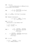
26.37: a)
.A1012.1
)F1055.4()1028.1(
C1055.6
4
106
8
RC
q
i
b)
.s1082.5)F1055.4()1028.1(
4106
RCτ
26.38:
.F1049.8
))3/12((ln)1040.3(
s00.4
)/ln(
7
6
0
/
0
vvR
τ
Cevv
RCτ
26.39: a) The time constant
:atSo.s1.11)F104.12()10895.0(
66
RC
.0)1(:s0
/
RCt
eCεqt
.C1070.2
)1()V0.60()F104.12()1(:s5
4
)s1.11/()s0.5(6/
eeCεqt
RCt
.C1042.4
)1()V0.60()F104.12()1(:s10
4
)s1.11/()s0.10(6/
eeCεqt
RCt
.C1021.6
)1()V0.60()F104.12()1(:s20
4
)s1.11/()s0.20(6/
eeCεqt
RCt
.C1044.7
)1()V0.60()F104.12()1(:s100
4
)s1.11/()s100(6/
eeCεqt
RCt
b) The current at time t is given by:
:atSo.
/ RCt
e
R
ε
i
.A1070.6
1095.8
V0.60
:s0
51.11/0
5
eit
.A1027.4
1095.8
V0.60
:s5
51.11/5
5
eit
.A1027.2
1095.8
V0.60
:s10
51.11/10
5
eit
.A1011.1
108.95
V60.0
:s20t
51.11/20
5
ei
A.1020.8
1095.8
V0.60
:s100
91.11/100
5
eit
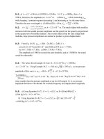
c) Charge against time:
Current against time:


