Tài liệu ACCESS POINTS ON NARROWBAND DATA CIRCUITS IN MODERN docx
Bạn đang xem bản rút gọn của tài liệu. Xem và tải ngay bản đầy đủ của tài liệu tại đây (111.53 KB, 6 trang )
A
CCESS
P
OINTS
O
N
N
ARROWBAND
D
ATA
C
IRCUITS
IN
M
ODERN
C
ARRIER
E
NVIRONMENTS
N
ETWORK
T
ECH
C
ONTROL
W
HITE
P
APER
Today’s transmission methods and equipment are robust and reliable and feature integrated network
monitoring, troubleshooting, maintenance, and provisioning systems. However, public carriers and
most major private networks have historically engineered their network’s physical plant to include
access points at which they can gain quick and organized “hard-contact” access to any particular
circuit path.
Typically, these access points were comprised of analog jackfields with “line-drop-monitor” access
capability. With these jackfields, craftpersons could passively monitor and/or intrusively test circuits,
or perform circuit reconfigurations to bypass faulty paths or accommodate changes in traffic patterns.
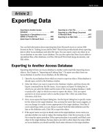
With the transition to the modern digital network hierarchy with
increased bandwidth, these analog jackfield bays gave way to more
functional DSX-1 and DSX-3 systems. A typical DSX-1 bay is shown
in Figure 1. Today we also see this “hard contact” access philosophy
extending into our emerging optical network transmission systems.
The reasons for this philosophy, as evidenced in virtually every
telephone office and even many outside plant (OSP) locations, are
simple. While networks are increasingly sophisticated and “self
healing”, the simple fact remains that physical things will break and
require physical intervention, and thus the way to restore or reroute
service is to change the physical arrangement of the circuit path. As
a result, providing easy access to networks continues to be a popular
practice.
Increasingly, carrier networks are being invaded with types of circuits on media different from the
traditional telco circuit physical plant. A rapidly growing share of office cabling are low speed data
circuits on RS232, V.35, and ANSI/EIA-530 interfaces.
Figure 1
210/97
440
Network Tech Control White Paper
Applications
The first significant application to bring these new interfaces to the central office was the
changeover to Signaling System #7 (SS7). In the past the telephone system consisted
only of the wires that carried our conversations. Switching instructions created by dialing
were sent on the same lines that carry voice conversations, as was information for long
distance billing. Thus, all signaling was in-band. In the late 1970s, a new system was
created to provide out-of-band signaling. Basically, a separate data network was created
between switching offices to work in conjunction with the voice networks. Phone com-
pany computers could use the signaling system to check and make sure a call could be
completed before actually switching the call all the way to the local loop only to find a
busy line. Later enhancements of the system allowed for information to be sent to specific
locations in the telephone network, and allowed for a way to send information from the
data line over the local loop in a short in-band burst of information.
How SS7 Works
There are three elements of the SS7 network:
• Service Switching Point (SSP) - A central office switch
• Signal Transfer Point (STP) - Packet switched data network
• Service Control Point (SCP) - A shared data base
Service Switching Points (SSP) are
central office switches that originate or
terminate telephone calls. Signaling
messages are sent between SSPs to set
up, manage, and release voice circuits
required to complete a call. An SSP may
also send a query message to a
centralized database to determine how
to route a call, for example the routing
of a toll-free 1-800/888 call in North America.
A Service Control Point (SCP) sends a response to the originating SSP which contains the routing
number(s) associated with the dialed number. An alternate routing number may be used by the SSP if
the primary number is busy or the call is unanswered within a specified time.
Network traffic between signaling points is routed via a packet switch called a Signal Transfer Point
(STP). An STP routes each incoming message to an outgoing signaling link based on the routing
information contained in the SS7 message. Because it acts as a network hub, an STP provides
improved utilization of the SS7 network by eliminating the need for direct links between signaling
points. SCPs and STPs are usually shared between multiple SSPs, thus it is typical to find only one of
two sets in a particular LATA.
Because the SS7 network is critical to call processing, SCPs and STPs are usually deployed in mated
pair configurations in separate physical locations to ensure network-wide service in the event of an
isolated failure. The SS7 data links, generally 56kbps V.35 circuits, are also duplicated, and frequently
protected by Network Tech Control facilities such as ADC’s PatchMate product line to ensure reliable
service on the SS7 network.
SS7 Links
SS7 Links
SSP
SCP
SCP
SSP
STP
STP
3
10/97
440
Network Tech Control White Paper
Signaling System #7 (SS7), the linking of the phone system with computers for switch-
ing purposes through the data link has allowed the phone system to become intelligent
by linking SS7 with databases. SS7 works as a packet switched digital transmission
medium. The digital circuits between the switching offices operate at 56kbps. Informa-
tion from the common databases controls the switching of calls and allows the transfer
of messages within the system. SS7 paved the way for a variety of new services referred
to as custom calling services. These include call blocking, call forwarding, caller ID and
similar service enhancements, many of which generate additional revenue for the local
phone company. SS7 will continue to enhance traditional basic telecommunication
services as well as improve the interconnection and inter-working of separate networks.
In addition to the inside network support applications such as SS7, the public networks
are also increasingly involved in providing narrowband data transport services such as
ATM and ISDN. While these services are usually “bundled up” into more traditional
wideband transport paths, at the individual customer interface point, they commonly
exist as narrowband (generally sub-56kbps rate) RS232, V.35, or ANSI/EIA-530 signal
interfaces on CSU’s, ATM switches, and other similar devices.
Clearly a means of gaining rapid and organized physical access to these circuits is
needed. They are simply too important to ignore.
Because of their physical complexity, these circuits cannot be gracefully integrated into
traditional access hardware such as jackfields or DSX systems. Fortunately, however,
a concept called “network tech control” has long existed in large private data centers in
the military and in data-transport-intensive industries such finance, transportation
reservations and similar applications. The products that have long provided organized
physical accesses to those networks are ready-made to fill the growing need in SS7,
ATM, and other public network applications.
In addition to referring to a family of physical products, the term network tech control
also refers to a network management concept. This concept is essentially identical to
the concept of a DSX installation, with a few enhancements based on the circuit-health
information inherently available on most data interfaces.
Network Tech
Control:
An old solution solves
new problems
4
10/97
440
Network Tech Control White Paper
In its simplest implementation, network tech
control is absolutely functionally identical to the
jackfield system alluded to earlier. Basically, all the
data physical circuits are concentrated into patch
panels that are equivalent to the familiar line-drop-
monitor jackfields common in analog telco environ-
ments. The familiar schematic depiction in Figure
2 is the literal heart and soul of the network tech
control concept.
At this simple physical access point, the following
functions can be performed.
Passive Monitoring
The lower monitor port provides a non-intrusive
access point that can accommodate a high impedance test device such as a data-
scope in monitor mode. This access style allows observance of actual circuit activity
without interruption of user traffic.
Segmentation for Testing
By use of a patch appearance, a craftperson can segment a circuit at any convenient
point and perform intrusive testing with rack-mounted or portable instrumenta-
tion.
Circuit Rerouting
By use of patch cords, circuits can be quickly rerouted to accommodate changes in
traffic flow on a temporary or semi-permanent basis.
Substitute Spare Equipment
Quick restoration of circuit functionality is critical in these high-value traffic
environments, and cannot wait for physical recabling to remove the faulty device
and insert a known good device into the traffic chain. Tech control panels allow the
termination of dedicated spares that can be quickly brought online with patch
cords, permitting the defective device to be replaced and recabled in a more deliber-
ate and less error-prone fashion.
Without these patch panels, any of the above actions can only be accomplished by
disconnecting interface cables and attaching instruments or spare equipment
directly to the cable. Frequently these connector locations are almost impossible to
reach because they are hidden deep in the back of equipment cabinets and obscured
by dozens of overlying cables. Mistakes are common, and adjacent circuits are also
often inadvertently disturbed in these congested areas.
Figure 2
1
2
3
4
5
6
7
8
9
10
11
12
13
14
15
16
17
18
19
20
21
22
23
24
25
1
2
3
4
5
6
7
8
9
10
11
12
13
14
15
16
17
18
19
20
21
22
23
24
25
510/97
440
Network Tech Control White Paper
These patch panels are available from ADC in a wide variety of configurations,
consisting of a chassis (module shelf) and usually 16 channels of patching.
Figure 3 shows a basic panel used for V.35 patching. These panels fit in 19-
inch wide racks and are 5.25 inches high. Other versions are available for
RS232, ANSI/EIA-530, and X.21 interface standards.
Besides the “plain” patch panels described so far, ADC also has designed a
series of patching equipment with extended features such as circuit activity
indicators (LEDs) and a variety of alarming functions.
Patching with these additional features is commonly installed on particularly
high-value circuits, such as the data lines at SS7 signal transfer points (STPs)
where a failure of a link could be especially disruptive. The alarm function
could be programmed for an anticipated alarm circumstance, such as lack of
data flow, and would alert personnel in the vicinity of the circuit problem.
The activity indicators give an “at a glance” status of circuit behavior without
the attachment of test equipment. A V.35 panel with these features is shown
in Figure 4. Power supplies are available for AC and 48VDC environments.
Patch panels that are augmented with remote control “AB” switching are also
available. These panels are can be used in situations (dark sites or offices not
staffed 7x24) where circuit reconfiguration must be accomplished by
craftpersons at another location. These panels include the usual patching for
use by on-site personnel, plus local control of the switch settings. Such a
panel for RS232 circuits is shown in Figure 5. Some of these panels can also
be configured as “automatic fallback” switches, switching to alternate equip-
ment or routing based on pre-determined alarm conditions on the primary
path.
For a more complete description of this network tech control equipment,
including various application examples, obtain the ADC “Network Control
Products” catalog , 6
th
edition, literature number 517. This information can
be ordered by calling (612) 946-3434, or 1-800-366-3891, or on the internet
at: />Figure 3
Figure 4
Figure 5