Tài liệu Soneplex Broadband and Soneplex Loop Extender Systems Alarm/Performance Remote Retrieval Options pdf
Bạn đang xem bản rút gọn của tài liệu. Xem và tải ngay bản đầy đủ của tài liệu tại đây (184.9 KB, 12 trang )
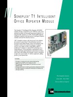
Application Note 1207
®
Telecommunications
Soneplex Broadband and
Soneplex
Loop Extender Systems
Alarm/Performance Remote
Retrieval Options
This application note provides detailed alternatives for transporting the Soneplex
Broadband and Soneplex Loop Extender alarm and performance information from a
remote location back to the central/hubbing location.
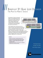
The Soneplex Broadband System is used as an intelligent network hub for DS1 hicap
distribution in the local loop. The network interface is one standard electrical DS3
signal. This DS3 signal is demultiplexed into twenty-eight DS1 circuits, which can
then be delivered to up to twenty-eight remote locations utilizing either fiber or
copper facilities.
Overview
®
®
Figure 1
HSW TAUHSP MXW MXP
APU
MPU
D
L
X
H
L
X
C
H
L
X
C
R
L
X
O
D
S
2
W
O
D
S
2
P
Q
L
X
W
T
1
R
P
T
R
OPTICAL DS2
(6.3 Mbps)
DS3
2B1Q
H
L
X
R
Q
L
X
P
H
L
X
R
X.25
TBOS
EIA-
422
EIA-
232
CRAFT INTERFACE
2
Alarm/Performance Remote Retrieval Options
Application Note 1207
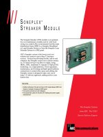
The Soneplex Loop Extender System is an intelligent network element providing DS1
services in point-to-point or point-to-multipoint applications. The network interface is
twenty-eight standard electrical DS1 signals. The system can be used in a stand-alone
configuration or with any multiplexer or network element that generates a standard
DS1 signal.
Overview
OSS Interfaces
The Soneplex systems provide several different monitoring and alarming interfaces that
may be connected either locally or remotely to an external alarm collection device. The
Soneplex chassis has 5 physical ports used for interconnection to the external alarm
network. A brief description of the ports and their functionality follows:
Port Function
Port 1 EIA-422 Telemetry Byte Oriented Serial (TBOS)
Port 2 EIA-232 TBOS, Craft Interface or TL1
Port 3 EIA-232 X.25 (no external PAD necessary),
Craft Interface, TL1 or TBOS
Port 4 EIA-422 Chassis to chassis communications
Port on front of MPU TBOS, Craft Interface or TL1
EIA-232
These five ports are tied to the main processor unit (MPU) located in the right hand slot
of both chassis. Each system module within the Soneplex Broadband and Soneplex Loop
Extender chassis provides provisioning, alarm and performance information that is
uploaded to the MPU. The MPU disseminates and stores the total system performance
and provides the OS interfaces listed above. The MPU contains a central processor and
non-volatile memory. In addition, each module has front panel LED indicators for
visible identification of module status.
The ADC DS3 Fiber Loop
Converter (FLC) (referred
to throughout this applica-
tion note) interfaces with
one DS3 signal and con-
verts the signal to an
optical signal. This signal
is then transported to a
remote DS3 FLC where it
is converted back from an
optical signal to an electri-
cal signal. This system can
be configured in an
unprotected or 1:1 pro-
tected configuration.
Figure 2
H
L
X
C
H
L
X
C
H
L
X
C
H
L
X
C
5 6 7 Q
L
X
Q
L
X
12 13 14 15 16 17 15 19 20 21 22 23 24 R
L
X
26 27 28 M
P
U
A
P
U
CENTRAL OFFICE/ HUB
CUSTOMER PREMISES
REMOTE ONE POSITION
WALL MOUNT CHASSIS
H
L
X
R
CUSTOMER PREMISES
REMOTE RACK MOUNT
OR WALL MOUNT CHASSIS
400 STYLE
MOUNTING UP TO 4 HLXR
Q
L
X
Q
L
X
DISTRIBUTION
LOOP (12 KFT)
OPTICAL BUDGET
UP TO 20 MILES
H
L
X
R
H
L
X
R
H
L
X
R
CSU
NID
DS1
(3000' BETWEEN
SPAN REPEATERS)
TBOS
EIA-422
EIA-232
X.25
CUSTOMER PREMISES
REMOTE WALL MOUNT CHASSIS
UP TO FOUR QLXs PER CHASSIS
CUSTOMER PREMISES
3
Application Note 1207Alarm/Performance Remote Retrieval Options
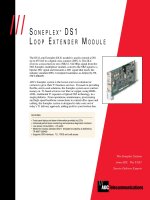
The communication ports, the MPU and APU modules are the same for both the
Soneplex Broadband and Soneplex Loop Extender systems.
Rear View
Soneplex Loop Extender Chassis
Soneplex Broadband Chassis
Rear View with Cover Removed
Figure 3
Figure 4
2 - 4
RX
TX
NO -------| |---- C -----|/|----- NC
ALARM
CR VIS
CR AUD
MJ VIS
MJ AUD
MN VIS
MN AUD
RMT
ACO
RX
TX
PORT 4
RS-422
+
-
+
-
PORT 1
RS-422
+
-
+
-
ACO
IN
PORT 3
RS-232
DTE
PORT 2
RS-232
DTE
J-29 J-30
SHIELD
GND
1
2
3
4
5
6
7
8
1
2
3
4
5
6
7
8
1-1
1-2
1-3
1-4
2-1
2-2
2-33-13-34-14-35-15-36-16-3
7-1
7-3
2-43-23-44-24-45-25-46-26-47-27-4
BITS
SEC
BITS
PRI
DS1
REF
HSKP IN
-1-
-2-
-3-
-4-
-5-
-6-
-7-
-8-
-48 A
-48 B
RTN A
RTN B
FRAME GND
T1
R1
L2
T
R
L1
T1
R1
L2
T
R
L1
T1
R1
L2
T
R
L1
T1
R1
L2
T
R
L1
T1
R1
L2
T
R
L1
T1
R1
L2
T
R
L1
T1
R1
L2
T
R
L1
T1
R1
L2
T
R
L1
T1
R1
L2
T
R
L1
T1
R1
L2
T
R
L1
T1
R1
L2
T
R
L1
T1
R1
L2
T
R
L1
T1
R1
L2
T
R
L1
T1
R1
L2
T
R
L1
T1
R1
L2
T
R
L1
T1
R1
L2
T
R
L1
T1
R1
L2
T
R
L1
T1
R1
L2
T
R
L1
T1
R1
L2
T
R
L1
T1
R1
L2
T
R
L1
T1
R1
L2
T
R
L1
T1
R1
L2
T
R
L1
T1
R1
L2
T
R
L1
T1
R1
L2
T
R
L1
T1
R1
L2
T
R
L1
T1
R1
L2
T
R
L1
T1
R1
L2
T
R
L1
T1
R1
L2
T
R
L1
STS - 1/DS3
TX
RX
PORT 4 CHASSIS
TO CHASSIS
CRITICAL/MAJOR/MINOR
AND HOUSEKEEPING ALARMS
PORT 1
TBOS
PORT 2
CRAFT/TL1
PORT 3
X.25/TBOS/
CRAFT/TL1
CRITICAL / MAJOR / MINOR
AND HOUSEKEEPING ALARMS
PORT 1 TBOS
PORT 2
TBOS/CRAFT/TL1
PORT 3 X.25/TBOS/
CRAFT/TL1
-48 V POWER
A AND B FEEDS
FRAME
GROUND
4
Alarm/Performance Remote Retrieval Options
Application Note 1207
Dry Relay Contacts
The Soneplex Broadband and Soneplex Loop Extender chassis have critical, major,
minor and remote dry relay contacts for alarming.
Alarm Indication
Critical Generated if six or more DS1s are in alarm
Major Loss of one or more DS1s/service affecting alarms
Minor All other alarms
Remote Any remote alarm received at the hubbing point
The alarm processor unit (APU) provides the critical, major and minor alarm indications
and dry relay contacts for the Soneplex Broadband and Soneplex Loop Extender systems.
These alarms are available as normally open or normally closed contacts which appear as
wire-wrap pins on the backplane. Eight housekeeping alarm inputs which appear as
contact wire-wrap pins are also located on the chassis backplane. These housekeeping
alarm inputs are retrieved by the MPU and are reported through the craft interface,
TBOS, TL1 commands and the X.25 port.
TBOS
The TBOS (Telemetry Byte Oriented Serial Protocol) interface is used for status and
control. The TBOS interface is a reliable and easy to use means of communicating
transmission alarm information between a monitoring system and the Soneplex system.
TBOS communications may also be optioned through the craft interface, Port 1, Port 2,
or Port 3.
The TBOS ports are configured as an asynchronous, serial, half-duplex interface operat-
ing at either EIA-422 or EIA-232 signal levels at a speed of 2400 bps. The Soneplex
Broadband and Soneplex Loop Extender systems each use 8 displays, 512 bits. Status
and command displays are supported.
TL1 Interface
Transaction Language 1 (TL1) commands may be used to communicate with both the
Soneplex Broadband and Soneplex Loop Extender systems either locally or from a
remote location. TL1 communication may be optioned through the craft interface port,
Port 2 or Port 3. A full complement of TL1 commands and responses are supported
including:
• autonomous alarms • administration
• performance monitoring • security commands
• loop back
Craft Interface
Three EIA-232 25-pin D subminiature connectors provide the craft interface for a VT100
or compatible terminal. One connector is located on the MPU front panel and is config-
ured as a DCE for local operation. Port 2 and Port 3 are located on the rear of the
chassis and are configured as a DTE for remote operation. The craft interface may be
optioned for auto baud or data rates up to 9600 bps. The craft interface provides local
and remote access for provisioning, performance monitoring and administrative tasks.
X.25 Interface
Port 3 is a serial EIA-232 25-pin D subminiature connector that can support two logical
connections over an X.25 connection. These two logical connections are in the form of
permanent virtual circuits (PVC). The PVCs can be configured for craft interface or TL1
commands.
5
Application Note 1207Alarm/Performance Remote Retrieval Options
Option 1
Alarming via Dry
Relay Contacts
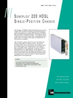
The first option to bring back remote alarms to a central location takes the dry relay
contacts of the Soneplex Broadband system and/or the battery back-up system and
transports them to the central location using the DS3 FLC overhead. As seen in Figure
5, the Soneplex chassis and battery back-up are fed into the DS3 FLC housekeeping
alarm inputs at the remote location and are reported back through the fiber optic
overhead to the central location where they are monitored through either TBOS or dry
relay contacts. Each DS3 FLC is capable of transporting one remote housekeeping
alarm back to the central location which equates to a total of two alarms when operating
in the DS3 protect configuration. This option works when the DS3 FLC is used as a
fiber optic transport back to the central location. Typically, the DS3 FLCs are installed
in pairs, providing 1:1 protection of the DS3 circuit. Therefore, two housekeeping alarm
indications may be transferred back to the central location. It is recommended that the
major alarm, which indicates the loss of one or more DS1 signals, be designated for
transfer. The second alarm can be used for minor alarms from the Soneplex or battery
back-up system.
NOTE:
• FLC MPU is not required for operation. If TBOS is required at a central
location, an FLC MPU is required.
• DS3 FLCs shown in a protected configuration.
Figure 5
CENTRAL LOCATION
REMOTE LOCATION
(1) DS3
ELECTRICAL
ALARM
ALARM
(1) ELECTRICAL
DS3
TBOS
REMOTE
ALARM
DRY RELAY
CONTACTS
SONEPLEX
BROADBAND
CHASSIS
BATTERY
BACK-UP
SYSTEM
DS3 FLC
DS3 FLC
MPU
W
P
DS3 FLC
DS3 FLC
W
P
-48 Vdc