Tài liệu Lab 4.2.9b Fluke 620 Cable Tester – Faults pptx
Bạn đang xem bản rút gọn của tài liệu. Xem và tải ngay bản đầy đủ của tài liệu tại đây (96.67 KB, 3 trang )
1 - 3 CCNA 1: Networking Basics v 3.0 - Lab 4.2.9b Copyright 2003, Cisco Systems, Inc.
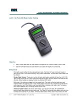
Lab 4.2.9b Fluke 620 Cable Tester – Faults
Objective
• Learn the Cable Test - Pass / Fail features of the Fluke 620 LAN CableMeter or an equivalent
tester.
• Learn how to use a cable tester to check for the proper installation of unshielded twisted pair
(UTP) for an Ethernet network.
• Test different cables to determine some problems that can occur from incorrect cabling
installation and termination.
Background / Preparation
Basic cable tests can be very helpful in troubleshooting cabling problems with UTP. The Cabling
infrastructure or cable plant in a building is expected to last at least ten years. Cabling-related
problems are one of the most common causes of network failure. The quality of cabling components
used, the routing and installation of the cable, and quality of the connector terminations will be the
main factors in determining how trouble-free the cabling will be.
2 - 3 CCNA 1: Networking Basics v 3.0 - Lab 4.2.9b Copyright 2003, Cisco Systems, Inc.
Prior to starting the lab, the teacher or lab assistant should have several correctly wired CAT 5
cables to test. The cables should be both straight-through and crossover. There should also be
several CAT 5 cables created with problems. Cables should be numbered to simplify the testing
process and to maintain consistency. The following resources will be required:
• CAT 5 straight-thru and crossover wired cables of different colors, some good and some bad
• CAT 5 straight-thru and crossover wired cables with open wire connections in the middle or one
or more conductors shorted at one end that are different colors and different lengths
• Cable Tester, which is Fluke 620 LAN CableMeter or something similar, to test cable length
Step 1
Turn the rotary switch selector on the tester to the TEST position. Press the SETUP button to enter
the setup mode and observe the LCD screen on the tester. The first option should be CABLE. Press
the UP or DOWN arrow buttons until the desired cable type of UTP is selected. Press ENTER to
accept that setting and go to the next one. Continue pressing the UP/DOWN arrows and pressing
ENTER until the tester is set to the following cabling characteristics:
Tester Option Desired Setting – UTP
CABLE: UTP
WIRING: 10BASE-T or EIA/TIA 4PR
CATEGORY: CAT 5
WIRE SIZE AWG 24
CAL to CABLE? NO
BEEPING: ON or OFF
LCD CONTRAST From 1 thru 10 (brightest)
Step 2
For each cable to be tested, use the following procedure. Place the near end of the cable into the
RJ-45 jack labeled UTP/FTP on the tester. Place the RJ-45-RJ-45 female coupler on the far end of
the cable. Then insert the cable identifier or wiremap tool into the other side of the coupler. The
coupler and the cable identifier are accessories that come with the Fluke 620 LAN CableMeter.
Step 3
Using the tester TEST function and a Cable ID Unit for UTP, the functionality of the cable can be
determined. Perform a basic cable test on each of the cables provided. Then fill in the following table
based on the result for each CAT 5 cable tested. For each cable, write down the number and color,
whether the cable is straight-through or crossover or coaxial, the tester screen test results, and what
3 - 3 CCNA 1: Networking Basics v 3.0 - Lab 4.2.9b Copyright 2003, Cisco Systems, Inc.
the problem is. For UTP cables, press the DOWN arrow or UP arrow to see all pairs.
Cable No. Cable Color Tester Test Results Problem
1
2
3
4