Analysis of the characteristics of bimetallic and semiconductor he 2021 meas
Bạn đang xem bản rút gọn của tài liệu. Xem và tải ngay bản đầy đủ của tài liệu tại đây (5.18 MB, 10 trang )
Measurement 182 (2021) 109713
Contents lists available at ScienceDirect
Measurement
journal homepage: www.elsevier.com/locate/measurement
Analysis of the characteristics of bimetallic and semiconductor heat flux
sensors for in-situ measurements of envelope element thermal resistance
Oleksandra Hotra a, *, Svitlana Kovtun b, Oleg Dekusha b
a
b
Department of Electronics and Information Technology, Lublin University of Technology, Nadbystrzycka Str. 38D, 20-618 Lublin, Poland
Monitoring and Optimization of Thermal Processes Department, Institute of Engineering Thermophysics of NAS of Ukraine, M. Kapnist Str. 2a, 03057 Kyiv, Ukraine
A R T I C L E I N F O
A B S T R A C T
Keywords:
Heat flux sensor
Metrological characteristics
In-situ method
Thermal resistance measurement
Monitoring of the thermal resistance of building envelopes for assessing their energy efficiency is carried out
through in-situ measurements of the heat flux. It is therefore necessary to take into account not only the heat
transfer conditions of the studied object but also the characteristics of the measuring instruments, which may
depend on these conditions. This paper presents the results of a study of the characteristics of heat flux sensors of
two types —bimetallic and semiconductor — which are the most common in the control of building envelopes.
The case studies were focused on the characteristics of the sensors, such as the conversion coefficient (inversely
proportional to sensitivity to the heat flux), the temperature dependence of the conversion coefficient, the
response time of the sensors, and the emissivity of the sensor surface. The conversion coefficient of a bimetallic
sensor was determined under the conditions of conduction and radiation supply of heat energy, which revealed
the dependence of the conversion coefficient on the heat transfer conditions of the sensor surface. The value of
the emissivity of the semiconductor sensor surface is lower than that of bimetallic sensors, and the time constant
of bi-metallic sensors is two times less than that of semiconductor sensors. Verification of the obtained results
was carried out by studying the metrological characteristics of the multi-channel thermal resistance control
system, which included bimetallic heat flux sensors as sensitive elements. Thus, we suppose that the results of our
study could be used to improve the accuracy in measuring the thermal resistance of building envelopes by the
correct selection of heat flow sensors, or by making corrections to the measurement results that take into account
the influence of experimental conditions on the characteristics of the sensors.
1. Introduction
Thermal resistance is one of the main informative characteristics
when monitoring the quality of insulating materials and the thermal
stability of envelope elements. The thermal resistance is a measure of
how well an envelope element resists heat losses. The actual values of
thermal resistance, as a key indicator used in the assessment of the en
ergy efficiency of a building, are required to ensure compliance with
energy performance strategies and with energy use.
The thermal resistance of building envelope elements in the design
phase is estimated according to ISO 6946 [1] or ISO 10211 [2] by direct
measurement of the thermal conductivity of each material [3], and
calculations using the guarded hot plate method according to ISO 8301
[4] or by a heat flux meter according to ISO 8302 [5]. However, the real
thermal resistance of building envelope elements does not always agree
with the calculated value, for various reasons [6]. Thus, it is important
to measure and analyze the building envelope thermal resistance in-situ.
Common measurement methods for thermal resistance estimation in
existing buildings are methods based on ISO 9869 [7] and ASTM C 1155
[8]. These standards differ from the methods of in-situ measurement
data analysis of the thermal building envelope. The ISO 9869 standard
introduces the Average method and Dynamic method, while the ASTM C
1155 standard introduces the Summation method and Least Square
method. All these methods require the measurement of the internal and
external surface temperature and the internal heat flux for at least three
days.
There are many factors which have a significant impact on the heat
flux measurements at the realization of an in-situ method [9–11].
Therefore, researchers have studied the factors of thermal mass [12],
variations of daily outside temperature, direct sun radiation [13], pre
cipitation and other outside climatic conditions which do not allow
establishment of stationary heat conditions, different heating systems
* Corresponding author.
E-mail address: (O. Hotra).
/>Received 9 March 2021; Received in revised form 30 April 2021; Accepted 3 June 2021
Available online 8 June 2021
0263-2241/© 2021 The Author(s). Published by Elsevier Ltd. This is an open access article under the CC BY license ( />
O. Hotra et al.
Measurement 182 (2021) 109713
influence on the physical parameters of relative humidity [14], and heat
capacity of the element [15].
Another factor is the complex shape of the building envelope ele
ments, including such heterogeneous zones as brickwork, translucent
elements (in particular windows), a reinforcing belt, and so forth. In
many research works, data are included to determine the thermal
resistance of separate homogeneous areas, most often windows [16–18].
The results of the theoretical study of the methodological errors in
measuring the heat flow when the heat flux sensor is located on the
surface of the enclosing structure are discussed in a previous paper [19].
In this case, heat exchange with the environment occurs under boundary
conditions of the third type. It was found that the main factors affecting
the methodological measurement error are the following: heat transfer
coefficient, radius of the sensor, thermal conductivity of the envelope
structure, and thermal resistance of the sensor. Researchers have shown
that in order to reduce the methodological error, it is necessary to use
the sensor with the minimum thermal resistance, which can be obtained
by reducing the thickness of the sensor or increasing the geometric di
mensions of the sensor, with the maximum emissivity of the sensor
surface and the shortest response time. Thus, measuring instruments
used for in-situ thermal resistance experiments also affect the mea
surement results of heat flux [20].
The development of systems for measuring the thermal characteris
tics of buildings and construction elements is carried out by such wellknown companies as Hukseflux (TRSYS01 high-accuracy building
thermal resistance measuring system with two measurement locations);
Green TEG AG (gO measurement system for the assessment of the Uvalue, humidity and further parameters); and FluxTeq (FluxTeq R-value
measurement system). The disadvantage of the Hukseflux and Green
TEG AG measuring systems is the use of heat flux sensors of one type and
size, which makes it impossible to conduct studies of various elements of
the building, in particular windows and window frames. The FluxTeq
system provides such an opportunity, but a small number of measuring
channels, which limits the number of control zones to two and does not
allow monitoring of complex shaped building envelopes.
From the above, it follows that when measuring the heat flux by the
in-situ method for determination of envelope element thermal resis
tance, it is necessary to take into account the characteristics of the
measuring instruments, which depend on the conditions of the experi
ment. The aim of this article was to study such characteristics of heat
flux sensors as temperature dependence of the conversion coefficient,
emissivity of the sensor surface, and influence of heat transfer conditions
on the conversion coefficient of sensors. This paper focuses on the
comparison of the main characteristics of the sensors developed by us
with sensors from other manufacturers, which are actively being used by
researchers for measuring the thermal properties of building envelopes
by the in-situ method. Due to the fact that heat flux sensors are part of
the measurement systems, it is also advisable to study the metrological
characteristics of a multichannel thermal resistance control system. The
main novelty of this work resides in the use of a complex approach for
determining the characteristics of heat flux sensors, taking into account
the influence of the conditions of their subsequent use for in-situ mea
surements of envelope element thermal resistance.
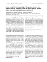
2.1.1. Bimetallic heat flux sensors
The sensor is a spiral structure of thermoelements, which are placed
in a special matrix and filled with an insulating epoxy compound with a
heat-conducting filler to give it the shape of a monolithic plate (see
Fig. 1). Such a sensor is a so-called “additional wall”, on the opposite
sides of which are placed the junctions of thermocouples. Under the
influence of heat flux passing through the additional wall and, accord
ingly, in parallel through all elements of the thermocouple, a tempera
ture difference occurs between the junctions, which results in an electric
signal being generated in each of the thermocouples in the series. The
total output signal of the sensor is proportional to the amount of heat
flux. That is, when measuring a stationary heat flux using such a sensor,
its density is determined in accordance with the Fourier law, by the
temperature difference on the outer surfaces of the sensor.
Features of the manufacturing technology of such sensors allow the
design of a sensor of any configuration with a predetermined sensitivity.
The sensitivity of the sensor varies due to the thickness of the thermo
couple material deposition on the wire. The temperature dependencies
of the conversion coefficient for sensors made of a constantan spiral with
different percentages of galvanically deposited nickel are graphed in
Fig. 2.
As one can see, changing the percentage of galvanically deposited
nickel, we can not only vary the conversion coefficient of the sensor, but
also reduce the temperature dependence of the conversion coefficient.
2.1.2. Semiconductor heat flux sensors
Semiconductor sensors based on the Peltier effect, which are
designed to work as thermoelectric current generators or refrigerators,
have become widespread. However, they can also operate in heat flux
measurement mode, acting as a sensor in measurement systems.
The structure of the semiconductor sensor is depicted in Fig. 3. It
consists of p- and n-type semiconductor elements connected in pairs by
copper buses (switching plates) into a single electrical circuit, located
between the ceramic boards. Semiconductor elements are manufactured
using alloys of telluride and selenides of bismuth and antimony. The
ceramic plate of the semiconductor sensor, to which the output wires are
attached, is called the “hot side”, and the other ceramic plate is called
the “cold side”.
The following semiconductor sensors in the mode of heat flux sensors
and bimetallic sensors were studied:
a) Thermoelectric semiconductor generator module PGM-15–250,
which has standard dimensions of 40 × 40 × 3.4 mm and contains
200 BiTe thermoelements, with a thermocouple size of 1.45 × 1.45
× 0.83 mm;
b) Cooling module TEC1-12703, which has standard dimensions of 30
× 30 × 3.5 mm and contains 127 thermocouples;
c) Thermoelectric semiconductor Peltier (three pieces) cooling modules
TEC1-12706, which have standard dimensions of 40 × 40 × 3.8 mm
and contain 127 BiSn thermocouples;
d) Disc-shaped thermoelectric bimetallic heat flux sensors, which are
30 mm in diameter and 2 mm thick, with a constant-cell coil of NiConst coated wire (Ni-Const); these sensors are of our own
production;
e) Rectangular-shaped thermoelectric bimetallic heat flux sensors with
dimensions of 20 × 80 × 2 mm and a constant-cell coil of Ni-Const
coated wire (Ni-Const); these sensors are of our own production;
f) Disc-shaped thermoelectric heat flux sensor, 50 mm in diameter and
3 mm thick, PU 22 series by Hukseflux.
2. Materials and methods
2.1. Heat flux sensors used in the monitoring of thermal resistance of the
envelope structure
This paper describes a study of semiconductor sensors and
developed-by-us bimetallic heat flux sensors for measuring the thermal
resistance of building envelopes using conductive and radiation
methods. In this study, we investigated the characteristics of heat flux
sensors, which are most commonly used for in-situ measurements of
envelope elements [20–24]. Below is a description of the designs and the
principle of operation of these two types of sensors.
Fig. 4 shows photos of the investigated sensors indicated above,
under items “a”, “b”, “c”, “d”, “e”, “f”.
All semiconductor sensors have ceramic housings (Al2O3), and
bimetallic sensors “d” and “e” are filled with a UP-610 epoxy resin
compound. The operating temperature ranges for sensor “a” is up to
230 ◦ C, for sensors “b” and “c” is up to 138 ◦ C, for sensors “d” and “e” is
2
O. Hotra et al.
Measurement 182 (2021) 109713
Fig. 1. The structure of the bimetallic heat flux sensor.
up to 200 ◦ C, and for sensor “f” is up to 90 ◦ C. Technical specifications of
the studied sensors are given in Table 1.
2.2. Experimental equipment and methods
In order to measure the surface heat flux density using the above
mentioned sensors, the following metrological and operational charac
teristics should be determined: the conversion coefficient, the
dependence of the conversion coefficient on temperature, the inertia of
the sensor, and the emissivity of the sensor surface.
The conversion coefficient of the sensor is determined by passing the
thermal energy of a fixed value through the heat-sensitive surface of the
investigated sensor, and measuring the output signal. This study was
conducted using the conduction and radiation methods of heat energy
supply, which correspond to different conditions of heat exchange
during the operation of sensors.
In order to determine the emissivity of the sensor surface, we used a
heat metric method for calculating the thermal radiation characteristics
of the surface [25,26]. This method consists of determination of the ratio
of the infrared radiation power absorbed by the surface to the incident
radiation power from the heat source.
The radiation method for determining the conversion coefficient of
the sensor lies in the fact that thermal radiation of a fixed density from a
source of thermal radiation is simultaneously supplied to the reference
and the studied sensors, which are located on a thermostated heat sink.
At the same time, equidistance of both sensors from the source of
thermal radiation and the same values of the emissivity of their heatsensing surfaces are provided. The sensor conversion coefficient is
calculated by the following formula:
(
)/
K = Kref ∙Eref Esens ,
(1)
Fig. 2. Temperature dependencies of the conversion coefficient for bimetallic
heat flux sensors with variation of the percentages of galvanically depos
ited nickel.
Fig. 3. The structure of semiconductor sensor.
Fig. 4. Photos of the investigated sensors: “a”, “b”, “c” are semiconductor sensors and “d”, “e”, “f” are bimetallic sensors.
3
O. Hotra et al.
Measurement 182 (2021) 109713
Table 1
Technical specifications of sensors.
Sensor Model
PGM-15–250
“a”
TES1-12703
“b”
TES1-12706
“c”
bimetallic
sensor “d”
bimetallic
sensor “e”
PU 22
“f”
Thermoelements
Thickness [mm]
Dimensions [mm]
Filling material
Heat flux density range [W/m2]
Temperature range [◦ C]:
Min.
Max.
Accuracy [%]
200 BiTe
3.4
40 × 40
Al2O3
±2000
127 BiSn
3.5
30 × 30
Al2O3
±2000
127 BiSn
3.8
40 × 40
Al2O3
±2000
Ni-Const
2
30
epoxy resin
±2000
Ni-Const
2
20 × 80
epoxy resin
±2000
Not specify
3
50
PU
±2000
− 20
+230
Not specified
− 20
+138
Not specified
− 20
+138
Not specified
− 20
+200
±3
− 20
+200
±3
− 20
+90
±5
where E is the signal parameter (voltage) generated by the sensor (in
dexes ref and sens are used for the reference and studied sensor,
respectively), and Kref is the conversion coefficient of the reference
sensor.
Determination of the sensor emissivity of the sensor surface was
achieved using the thermometric method for determining the thermor
adiation characteristics of selective coatings, which consists of deter
mining the ratio of the power of the particle of infrared radiation
absorbed by the surface to the power of incident radiation from the heat
source [25,26]. The value of the emissivity of the sensor surface was
calculated by the following formula [26]:
)
(
[ (
) ]− 1
4
− q∙Seqv ε−h 1 − 1
εsens = q∙ σ Th4 − Tsens
,
(2)
K(t) = (W∙Ssens )/Esens ,
where W is the electrical power supplied to the main heater, Ssens is the
area of the sensor, and Esens is the signal parameter (voltage) generated
by sensor.
A conductive system was used for method implementation [27]. It
consisted of a heat block in which the studied sensor was placed and the
required temperature and thermal conditions were provided, and an
electronic block containing the means for regulating the thermal con
ditions, and receiving and processing primary measurement information
(Fig. 5).
The main elements of the heat block were an electric heater for
setting a heat flux of a fixed value, which was structurally combined
with a heat-shielding side screen, a heat-absorbing flat metal platform
combined with a finned radiator, and a clamping device. The heater
body was made of a high thermal conductivity metal that contributes to
the creation of isothermal conditions along its heat-transfer surface in
contact with the heat-absorbing surface of the sensor under study. An
electronic block provided the setting of the experimental conditions and
regulation and control of the temperature conditions, and obtained the
primary measurement information. The main characteristics of the
system are shown in Table 3.
The main advantage of the conductive system is its ability to supply
heat flux of low density, starting from 1 W/m2, which is very important
in the case of in-situ measurements of envelope elements with high
thermal resistance or in the case of a low temperature difference.
where q is the radiation heat flux from the heat source, σ is the StefanBoltzmann constant, Th is the temperature of the heat source, Tsens is
the temperature of the sensor surface, Seqv is the area ratio of the heat
source to the sensor area, and εh is the emissivity of the heat source.
The studies of sensor characteristics in radiation conditions were
performed using a radiation comparator for calibrating the heat flux
sensors and measuring the emissivity of coatings and material surfaces
[27].
The radiation comparator consisted of the emitter as the heat source
in the form of a flat blackbody model, the protective screen with a
mirror-reflecting surface, and the water-cooled heat sink where the
sensors were placed for the research. The investigated sensor was
compared with the reference heat flux sensor. The flow of thermal ra
diation of a fixed density from the emitter was simultaneously supplied
to the investigated and reference sensors located on a water-cooled heat
sink. In this case, the heat-absorbing surfaces of both sensors were
equidistant from the source of thermal radiation, and had the same
emissivity.
The design of the emitter, in combination with the mirror-reflecting
screen, thermostatically controlled at the same temperature as the heat
sink, provided an almost complete absence of convective heat flux in the
sensor location zone, with satisfactory uniformity in the distribution of
heat flux density.
The technical specifications of the radiation comparator are pre
sented in Table 2.
A conduction method of thermal energy supply provided a unidi
rectional stationary heat flow through a sensor at a certain temperature
value, to determine its density by measuring the electrical power sup
plied to the main heater and the signal generated by the sensor. This
made it possible to determine the individual conversion coefficient by
the absolute method of direct measurement. The conversion coefficient
at a fixed temperature was calculated by the following formula:
Table 2
Technical Specifications of radiation comparator.
Heat flux density range
Range of operating temperature values
Emissivity
(3)
100 … 104 W/m2
10…80 ◦ C
0.040…0.99
Fig. 5. Block-diagram of the conductive system.
4
O. Hotra et al.
Measurement 182 (2021) 109713
Table 3
Technical Specifications of conductive system.
Heat flux density range
Range of operating temperature values
1 … 2.104 W/m2
25…250 ◦ C
2.3. Running of experiments
In order to conduct the research in a radiation comparator, it was
necessary to ensure the same emissivity of the heat-sensing surfaces of
the investigated and reference sensors, for example by applying the
same coating to their surfaces. After that, the sensors were placed on the
thermostatically controlled heat sink as shown in Fig. 6 with use of the
contact greases [29], which allowed us to reduce the influence of contact
thermal resistance between the sensor and the heat sink. The results
were obtained by comparison of the output signals of the investigated
sensors with the signal of the reference sensor. The disc-shaped ther
moelectric bimetallic heat flux sensor, of 27 mm in diameter and 1.5 mm
thickness and with a constant-cell coil of Ni-Const coated wire, was used
as the reference sensor. Its metrological characteristics were determined
at the State Enterprise “Ukrmetrteststandart”, certified by ISO 17025.
According to the sensor calibration results, the expanded uncertainty of
heat flux measurement did not exceed 1.5% with an interval having a
95% level of confidence assuming a normal distribution. In the experi
ments, a constant temperature of the radiator of the installation was set
to 120 ◦ C and the temperature of the water-cooled refrigerating plate
varied in the range from room temperature up to 50 ◦ C. The radiation
heat flux ranged from 420 to 530 W/m2.
In the conductive method, the sensor is installed on the surface of the
heat sink as shown in Fig. 7, and is covered by a heater combined with a
heat shield. In order to improve the thermal contact between the
working surfaces of the installation and the investigated sensor, a
clamping device is used.
Under such conditions of sensor installation the maximum value of
contact thermal resistance in the investigated range of temperature does
not exceed 0,0005 m2⋅K/W [30]. According to the results of the calcu
lations given in [30], the influence of contact thermal resistance on the
measurement result does not exceed 0.2%.
Measurement of the sensor output signals was carried out after the
onset of the stationary thermal regime. In order to determine the con
version coefficient with high accuracy, the contacting surfaces of the
conductive system and investigated sensor should have the same
diameter. The measurement result is the average value of the output
signal (voltage) of the heat flux sensor obtained by processing of the
readings taken within 20 min. The studies were carried out with varying
the temperature of the heat sink, from 25 to 50 ◦ C, while the heat flux
density was set at 1000 W/m2.
Fig. 7. Bimetallic sensor PU 22 series indicated as “f”, mounted on the cooling
plate of the conductive system.
3. Results of sensors experimental studies
The results of the experimental studies of the emissivity of the sensor
surface ε are given in Table 3. In order to reduce the random component
of the uncertainty, five cycles of measurements were conducted, and the
average value of the emissivity was taken as the measurement result.
According to the results of previous studies [28], when measuring
the heat flux under unsteady conditions an important characteristic of
sensors is the time constant. The time constant is determined as the time
from the beginning of the stepwise change of the heat flux until the
output signal reaches a certain preset level of the steady-state value. It is
proportional to the square of its thickness and is inversely proportional
to the temperature conductivity [28]. Therefore, information on the
time constant of sensors at the levels of 0.63 (τ 0.63) and 0.95 (τ 0.95) of the
sensor signal is also given in Table 4.
In Fig. 8, the test results of the sensitivity of heat flux sensors PGM15–250 “a”, TES1-12703 “b” and TES1-12706 “c” (the three lines
graphed for “c” correspond to three sensors) are shown as the temper
ature dependence of their conversion coefficients obtained at five points
from the range of temperature values. Each point in the graph depen
dence is the average result of the measurement series at the given
temperature. The combined standard uncertainty of determining the
conversion coefficients of the sensors with a 95% level of confidence
does not exceed 3%.The test results of the bimetallic sensors “d” and “e”
are presented in Fig. 9.
The analysis of the obtained characteristics of the sensors shows that
each of them has its advantages and disadvantages. For example, the
advantages of the TEC1-12706 “c” module are the low cost and high
sensitivity (the lowest value of the conversion coefficient), and the
Fig. 6. Heat flux sensors mounted on the heat sink of the radiation comparator. (a) From left to right: semiconductor sensor PGM-15–250 indicated as “a”, reference
sensor indicated as “ref”, semiconductor sensor TEC1-12703 indicated as “b”; (b) reference sensor (left), bimetallic sensor PU 22 series indicated as “f” (right).
5
O. Hotra et al.
Measurement 182 (2021) 109713
Table 4
The experimental results of the emissivity of sensor surface ε and the response time of the sensors.
ε
τ0.63 [s]
τ0.95 [s]
PGM-15–250
“a”
TES1-12703
“b”
TES1-12706
“c”
Bimetallic sensor
“d”
Bimetallic sensor
“e”
PU 22
“f”
0.71
15
44
0.71
16
47
0.71
20
57
0.88
8
27
0.89
8
27
0.91
8
27
heat flux density measurement in the corresponding channels of the
developed system was determined as the standard uncertainty of the
heat flux measurement at two values of normalized surface density of
heat flux: (250 ± 10) W/m2 and (500 ± 20) W/m2. The uncertainty of
temperature measurement was determined by comparing of the tem
perature values obtained by the corresponding channels of the devel
oped system with the working standard: RTD thermocouple Pt-100 in
U2C ultra thermostat. The standard uncertainty of the temperature
measurement was performed at two temperature values: 0 ◦ C and
+50 ◦ C.
The standard uncertainty of the heat flux density measurement was
expressed as a relative standard deviation of experimental data under
the assumption of a normal distribution. The results of metrological
experimental studies for the heat flux measurement channels of the
developed system are given in Fig. 12.
The standard uncertainty of the temperature measurement in 22
channels of the developed system was expressed as an absolute standard
deviation of experimental data under the assumption of a normal dis
tribution. The results of metrological experimental studies for the tem
perature measurement channel of the developed system are given in
Fig. 13.
The expanded uncertainty of the surface heat flux density measure
ment of the developed system does not exceed 3%. It was obtained by
multiplying the combined standard uncertainty by a coverage factor 2
that produces an interval having a 95% level of confidence assuming a
normal distribution. The expanded uncertainty of the temperature
measurement does not exceed 1 ◦ C with an interval having a 95% level
of confidence assuming a normal distribution. Measurements of the
surface heat flux density are in the range from 1 to 500 W⋅m− 2 and
temperatures in the range from − 40 to +50 ◦ C.
advantages of the bimetallic sensors “d” and “e” are their relatively small
response time, the smallest thickness and thermal resistance, and the
ability to produce the desired shape and size.
In order to carry out a comparative analysis to determine the con
version coefficient of the sensors, depending on the method of supplying
thermal energy, after the research in a radiation comparator studies
were carried out in a conductive system. Due to the fact that with a
conductive heat energy supply, as mentioned in Section 2.3, an impor
tant factor affecting the accuracy of measurement results is the corre
spondence of the diameters of the sensor and the working surface of the
conductive system, only the PU22 sensor was subjected to these studies.
Fig. 10 shows the results of the study of the conversion coefficient of
sensor PU 22 “f” under supply of conduction and radiation thermal
energy. As we can see, the difference in the values of the conversion
coefficient is more than 14%. This indicates that heat transfer conditions
can have a significant effect on the results of the heat flux measurement.
4. Verification of metrological characteristics and comparison
test
For the purpose of in-situ measurements of thermal resistance ac
cording to ISO 9869–1 [7], the multichannel control system was created
[31]. The system was constructed using a set of temperature and bimetal
heat flux sensors (Ni-Const) (see Fig. 11), that allow us to take into ac
count the peculiarities of the envelope elements and ensure the ability to
conduct research on a large number of representative zones.
4.1. Metrological characteristics of the system
The multichannel information-measuring system was calibrated to
monitor the thermal resistance of the envelope elements. It consists of
eight heat flux sensors and 22 thermoelectric temperature sensors
(thermocouples). The verification of metrological characteristics was
carried out by laboratory certified according to ISO 17025 “Ukrmetr
testStandard”, jointly with the Institute of Engineering Thermophysics
of NAS of Ukraine (in further text: IET).
According to the test report of the certified laboratory, to confirm the
measuring capabilities of the system (measurement of heat flux and
temperature in the range of declared values), the tests were carried out
at two points of the declared range. Therefore, the uncertainty of the
4.2. Experimental study of the system with bimetallic heat flux sensors
For experimental studies of the developed monitoring system,
comparative tests were carried out using equipment of the certified
laboratory “Ukrmetrteststandart”.
The experiment was carried out on the window assembly with twochamber glazed system SPD 4 4i-14Ar-4 M1-12Ar-4i and PVC frame
(70 mm width) in the climatic chamber. The window assembly was
mounted in the climatic chamber with cold section (as imitation of the
Fig. 8. Temperature dependencies of the conversion coefficient of semi
conductor sensors: PGM-15–250 “a”, TES1-12703 “b”, TEC1-12706 “c”.
Fig. 9. Temperature dependencies of the conversion coefficient for bimetallic
sensors “d” and “e”.
6
O. Hotra et al.
Measurement 182 (2021) 109713
contact greases [29] were used, which allowed us to reduce the influ
ence of contact thermal resistance.
Theoretical thermal resistance values were calculated according to
standard EN ISO 10077–2 [37] (for the opaque parts of the window) and
according to standard EN 673 [38] (for translucent parts of the window).
Calculated values of the thermal resistance (R) and the area of homo
geneous zones (F) are follows:
R1-10 = 0.76 m2⋅◦ C/W and F1-10 = 1.669 m2 for the glazed system,
taking into account homogeneous zones (zones F1…F10 are marked
with white in Fig. 14);
R11-14 = 0.68 m2⋅◦ C/W and F11-14 = 0.324 m2 for the opaque part
of the glazed system sash, taking into account homogeneous zones
(zones F11…F14 are marked with green in Fig. 14);
R15-19 = 0.68 m2⋅◦ C/W and F15-19 = 0.339 m2 for the opaque part
of the glazed system frame, taking into account homogeneous zones
(zones F15…F19 are marked with blue in Fig. 14);
Rassembly = 0.73 m2⋅◦ C/W and Fassembly = 2.332 m2 for the
window assembly.
Fig. 10. Temperature dependencies of the conversion coefficient for sensors PU
22 “f”.
outer side) and warm section (as imitation of the inner side). It should be
noted that the investigation of thermal characteristics of building en
velope fragments in laboratory conditions is carried out using a Hotbox
apparatus. The Hotbox design features and the corresponding mea
surement methods are regulated by ASTM C1363 [32], ISO 8990 [33]
and EN 12412 [34]. However, in our research we have used recom
mendations of the local standard DSTU B V.2.6–17 [35], which regulates
the procedure of the windows assembly thermal resistance measurement
in a climatic chamber with application of heat flux sensors. This stan
dard specifies the location of the sensors. The same layout of sensors can
be applied for in-situ measurements.
The measurement systems of the certified laboratory “Ukrmetrtest
standart” and monitoring system developed in the IET with different
types of heat flux sensors were used simultaneously for performing the
tests. For the cold-junction compensation of thermocouples the
temperature-dependent bridge-type compensation circuit with constant
voltage was used [36].
Layout of homogeneous temperature zones on a window assembly
with a two-chamber glazed system SPD 4 4i-14Ar-4 M1-12Ar-4i and PVC
frame (width 70 mm) according to the test report of the certified labo
ratory is given in Fig. 14, a. The sensors were mounted on the envelope
elements marked by F1-19 (Fig. 14, b) according to recommendations of
standards ISO 9869 [7], ASTM C 1155–95 [8], and DSTU B V.2.6–17
[35] suggesting the installation of the sensors in the centers of uniform
temperature zones on the inner surface.
In the case of a combination of sashes and frames, the sensors should
be installed on the surfaces of the sashes and frames. For measurements
on sashes and frames, the sensor’s width should be not more than half of
the profile width [35]. To meet this requirement, sensors with di
mensions of 20 mm × 80 mm were used. For installation of the sensors
The stationary operating regime in the climatic chamber was set over
48 h. The ambient temperature in the cold and warm chambers at the
distance of 0.15 m from the window assembly was in the range of 20.74
and 18.98 ◦ C and between 24.26 and 26.48 ◦ C, respectively. The mea
surements were carried out over 24 h after stationary operating regime
setting.
Results obtained with the measurement system of the certified lab
oratory “Ukrmetrteststandart” and monitoring system developed in the
IET are given in Table 5. Data from the sensors of the developed
monitoring system were recorded with intervals of 5 min, and then
averaged accordingly [8].
In order to evaluate the results, a comparative analysis of the
calculated and measured values was carried out according to ISO 9869
[7]. For the glazed system the difference between results of comparison
is equal to 1.3%, exhibiting good agreement between the calculated and
measured values. In the case of the opaque part (frame) the difference
between results is equal to 11.7%, which is acceptable. For the opaque
part (sash) the difference between results equals to 19.1%, which is the
boundary permissible value.
It is probably connected with convective air flows in the sash, which
influence the R-value measurements but are not taken into account in
the calculation of the theoretical value of the thermal resistance of the
envelope element due to good agreement of the measured values of both
systems.
Thus, the results obtained indicate the correct operation of the
multichannel system with bimetal heat flux sensors, which allows us to
apply it for in-situ monitoring of the thermal resistance.
5. Conclusions
In this paper, a complex approach for determining the characteristics
of bimetallic and semiconductor heat flux sensors most commonly used
for monitoring the thermal resistance of building envelopes was intro
duced. The influence of specific conditions of their further use was taken
into account in in-situ measurements. The application of the radiation
method gives us the ability to study the emissivity of the sensors. This is
very important in cases when the sensor and envelope elements have
different emissivity values. The conductive method is important because
of the ability to supply the heat flux of low density, starting from 1 W/
m2. This is a crucial moment in the case of in-situ measurements of
envelope elements with high thermal resistance, or in the case of a low
temperature difference.
The following characteristics were determined: the conversion co
efficient (sensitivity to the heat flux), the dependence of the conversion
coefficient on temperature, the response time of the sensor, and the
emissivity of the sensor surface. As a result of the studies, it was found
Fig. 11. Module of the multichannel thermal resistance control system and
heat flux sensors [31].
7
O. Hotra et al.
Measurement 182 (2021) 109713
Fig. 12. Results of metrological experimental studies for the heat flux measurement channels of the developed system.
Fig. 13. Results of metrological experimental studies for the temperature measurement channels of the developed system.
Fig. 14. Window assembly: the glazed sys
tem is marked with white; the opaque part of
window assembly sash is marked with green;
the frame is marked with blue; (a) layout of
homogeneous temperature zones on a win
dow assembly: F1…F19 are the areas of ho
mogeneous zones; R1…R19 are thermal
resistances of the corresponding homoge
neous zones; (b) sensors layout: TS – tem
perature sensors marked with yellow, HFS –
heat flux sensors marked with brown. (For
interpretation of the references to color in
this figure legend, the reader is referred to
the web version of this article.)
8
O. Hotra et al.
Measurement 182 (2021) 109713
CRediT authorship contribution statement
Table 5
The results obtained on a window assembly.
Homogeneous zones
Average temperature
of the inner surface,
◦
C:
Glazed system
Opaque part (sash)
Opaque part (frame)
Average temperature
of the outer surface,
◦
C:
Glazed system
Opaque part (sash)
Opaque part (frame)
Average heat flux
density, W/m2:
Glazed system
Opaque part (sash)
Opaque part (frame)
Thermal resistance,
m2⋅◦ C /W:
Glazed system
Opaque part (sash)
Opaque part (frame)
Equipment of the
certified
laboratory
Developed
monitoring
system
Difference
between
results
20.22
20.05
17.97
19.8
20.35
18.35
0.42
0.3
0.38
Oleksandra Hotra: Conceptualization, Validation, Formal analysis,
Resources, Writing - review & editing. Svitlana Kovtun: Conceptuali
zation, Methodology, Validation, Investigation, Writing - review &
editing, Supervision. Oleg Dekusha: Conceptualization, Validation,
Investigation, Writing - review & editing, Visualization, Supervision.
Declaration of Competing Interest
− 14.89
− 12.51
− 15.80
− 15.2
− 12.91
− 15.3
0.31
0.4
0.5
45.85
40.90
57.00
46.6
41.3
56.5
− 0.75
0.4
0.5
0.76
0.80
0.59
0.75
0.81
0.6
0.01
0.01
0.01
The authors declare that they have no known competing financial
interests or personal relationships that could have appeared to influence
the work reported in this paper.
References
[1] ISO 6946, Building Components and Building Elements – Thermal Resistance and
Thermal Transmittance – Calculation Method, ISO, Geneva, Switzerland, 2007.
[2] ISO 10211, Thermal Bridges in Building Construction – Heat Flows and Surface
Temperatures – Detailed Calculations, ISO, Geneva, Switzerland, 2007.
[3] O. Hotra, O. Dekusha, A device for thermal conductivity measurement based on the
method of local heat influence, Przeglad Elektrotechniczny. 88 (5A) (2012)
223–226.
[4] ISO 8302, Thermal Insulation – Determination of Steady-State Thermal Resistance
and Related Properties – Guarded Hot Plate Apparatus, ISO, Geneva, Switzerland,
1991.
[5] ISO 8301, Thermal Insulation – Determination of Steady-State Thermal Resistance
and Related Properties – Heat Flow Meter Apparatus, ISO, Geneva, Switzerland,
1991.
[6] CITB Construction Industry Training Board; English Heritage; Stba Sustainable
Traditional Buildings Alliance. Performance and Energy Efficiency of Traditional
Buildings. 2012. Available online: .
uk/downloads/STBA-Gap-Analysis-StudyPerformance-and-Energy-Efficiency-of-Traditional-Buildings-Final-Version-(2).pdf
(accessed on 17 November 2020).
[7] ISO 9869-1, Thermal insulation–Building elements–In-situ measurement of thermal
resistance and thermal transmittance–Part 1: Heat flow meter method,
International Organization for Standardization, ISO, Geneva, Switzerland, 2014.
[8] ASTM C 1155-95, Standard practice for determining thermal resistance of building
envelope components from the in-situ data. Annual Book of ASTM Standards,
ASTM International, 2001.
[9] K.J. Kontoleon, D.K. Bikas, The effect of south wall’s outdoor absorption coefficient
on time lag, decrement factor and temperature variations, Energy Build. 39 (2007)
1011–1018, />[10] M. Scarpa, P. Ruggeri, F. Peron, M. Celebrin, M. De Bei, new measurement
procedure for U-value assessment via heat flow meter, Energy Procedia 113 (2017)
174–181, />[11] G. Desogus, S. Mura, R. Ricciu, Comparing different approaches to in situ
measurement of building components thermal resistance, Energy Build. 43 (2011)
2613–2620, />[12] P. Biddulph, V. Gori, C.A. Elwell, C. Scott, C. Rye, R. Lowe, T. Oreszczyn, Inferring
the thermal resistance and effective thermal mass of a wall using frequent
temperature and heat flux measurements, Energy Build. 78 (2014) 10–16, https://
doi.org/10.1016/j.enbuild.2014.04.004.
[13] C.A. Gueymard, W.C. du Pont, Spectral effects on the transmittance, solar heat
gain, and performance rating of glazing systems, Sol. Energy 83 (2009) 940–953,
/>´ Lakatos, F. Kalm´
[14] A.
ar, Analysis of water sorption and thermal conductivity of
expanded polystyrene insulation materials, Build. Serv. Eng. Res. Technol. 3
(2013) 407–416, />[15] R. Ricciu, A. Galatioto, L.A. Besalduch, G. Desogus, L. Di Pilla, Building Wall heat
capacity measurement through flux sensors, J. Sustainable Dev. Energy, Water
Environ. Syst. 7 (1) (2019) 44–56. />[16] G. Baldinelli, F. Bianchi, Windows thermal resistance: Infrared thermography aided
comparative analysis among finite volumes simulations and experimental methods,
Appl. Energy 136 (2014) 250–258, />apenergy.2014.09.021.
[17] V. Corrado, S. Paduos, New equivalent parameters for thermal characterization of
opaque building envelope components under dynamic conditions, Appl. Energy
163 (2016) 313–322, />[18] Y. Feng, Q. Duan, J. Wang, S. Baur, Approximation of building window properties
using in situ measurements, Build. Environ. 169 (2020), 106590, />10.1016/j.buildenv.2019.106590.
[19] L. Vorobiov, T. Hryshchenko, L. Dekusha, S. Kovtun, Methodical error in heat flow
density measuring, Metrol. Instrum. 5 (55) (2015) 9–15.
/journal1.
[20] X. Meng, B. Yan, Y. Gao, J. Wang, W. Zhang, E. Long, Factors affecting the in situ
measurement accuracy of the wall heat transfer coefficient using the heat flow
meter method, Energy Build. 86 (2015) 754–765, />enbuild.2014.11.005.
that the TEC1-12706 semiconductor sensor has the lowest value of
conversion coefficient, which allows them to be used in conditions of
low heat fluxes. The determination of the sensor conversion coefficient,
carried out with conductive and radiation supply of heat energy, made it
possible to reveal the influence of heat exchange conditions on the
characteristics of the sensors. Thus, at radiation heat exchange, the
sensor conversion coefficient increases by 14% compared with the
conduction heat exchange, which leads to a decrease in the sensitivity of
the measuring system and introduces an additional error in the mea
surement result. Bimetal heat flux sensors (Ni-Const) and bimetal sensor
PU 22 series have a relatively small time constant (τ0.63 = 8 s), which
together with a small thickness is a determining factor in heat flux
measurements in conditions of unsteady heat transfer.
To verify the obtained results, studies of the metrological charac
teristics of the multi-channel thermal resistance monitoring system of
building envelopes using the equipment of the Ukrmetrteststandart
laboratory, certified according to ISO 17025, were carried out. The
system included bimetal heat flux sensors (Ni-Const) and temperature
sensors. The manufacturing technology of bimetal sensors makes it
possible to produce them in any shape (round, square, rectangular) and
size, and with the necessary sensitivity, which allows research of up to
40 measurement zones contemporaneously, taking into account the
specifics of the envelope elements. As a result of comparative tests, it
was found that the difference between results of the temperature mea
surement did not exceed 0.5 ◦ C, and the difference between results of the
measurement of heat flux density was 0.75 W/m2. The obtained results
allow us to recommend bimetal heat flux sensors as the sensitive element
of a system for determining the thermal resistance of building envelopes
by the in-situ method. However, during comparison of the calculated
and measured values according to ISO 9869 [7], good agreement was
found only for the glazed system (difference between results equaled
1.3%). In the case of the opaque part (frame) the difference between
results was 11.7% and for the opaque part (sash) the difference between
results was equal to 19.1%, which is on the boundary of the permissible
values [7]. This fact could be explained by the presence of convective air
flows in the sash, which influence the R- or U-value measurements but
were not taken into account in the calculation of the theoretical value of
thermal resistance. In this case, EN 12412 [34] is a preferred standard
over DSTU B V.2.6–17 [35].
9
O. Hotra et al.
Measurement 182 (2021) 109713
[21] E. Genova, G. Fatta, The thermal performances of historic masonry: In-situ
measurements of thermal conductance on calcarenite stone walls in Palermo,
Energy Build. 168 (2018) 363–373, />enbuild.2018.03.009.
[22] E. Lucchi, Thermal transmittance of historical stone masonries: A comparison
among standard, calculated and measured data /, Energy Build. 151 (2017)
393–405, />[23] A.S. Anđelkovi´c, B. Gvozdenac-Uroˇsevi´c, M. Kljaji´c, M.G. Ignjatovi´c, Experimental
research of the thermal characteristics of a multi-storey naturally ventilated double
skin faỗade, Energy Build. 86 (2015) 766781, />enbuild.2014.11.007.
[24] J. Bros-Williamson, J. Stinson, C. Garnier, J. Currie, In-situ monitoring of thermal
refurbishment on pre-1919 properties in Scotland, Int. J. Sustainable Constr. 2 (1)
(2014) 26–33. />[25] T. Kr´
alík, V. Musilov´
a, P. Hanzelka, J. Frolec, Method for measurement of
emissivity and absorptivity of highly reflective surfaces from 20 K to room
temperatures, Metrologia 53 (2) (2016) 743–753, />[26] V. Babak, O. Dekusha, L. Vorobiov, S. Kobzar, S. Ivanov, The heat exchange
simulation in the device for measuring the emissivity of coatings and material
surfaces, in: Proceedings of IEEE 39th International Conference on Electronics and
Nanotechnology (ELNANO 2019) 2019, 301–304. Available online: https://ieeexp
lore.ieee.org/xpl/conhome/8767103/proceeding (accessed on 17 November
2020).
[27] V. Babak, S. Kovtun, O. Dekusha, Information-measuring technologies in the
metrological support of heat flux measurements, in: Proceedings of The Third
International Workshop on Computer Modeling and Intelligent Systems (CMIS2020) 2020, 2608, 379–393, Available online: />per29.pdf (accessed on 17 November 2020).
[28] L. Dekusha, S. Kovtun, O. Dekusha, Heat flux control in non-stationary conditions
for industry applications, in: 2019 IEEE 2nd Ukraine Conference on Electrical and
[29]
[30]
[31]
[32]
[33]
[34]
[35]
[36]
[37]
[38]
10
Computer Engineering (UKRCON), 2019, pp. 601–605, />enbuild.2014.11.007.
Y. He, Rapid thermal conductivity measurement with a hot disk sensor Part 2.
Characterization of thermal greases, Thermochimica Acta 436 (2005) 130–134,
/>L. Dekusha, L. Vorobiov, T. Hryshchenko, G. Mendrul, S. Kovtun, Provision of the
standard level of measurements heat flux density in Ukraine, Ind. Heat Eng. 4 (31)
(2009) 109–116. />V. Babak, O. Dekusha, S. Kovtun, S. Ivanov, Information-measuring system for
monitoring thermal resistance, Available online: CEUR Workshop Proc. 2387
(2019) 102–110 />ASTM C1363-19, Standard Test Method for Thermal Performance of Building
Materials and Envelope Assemblies by Means of a Hot Box Apparatus, ASTM
International, West Conshohocken, PA, 2019, www.astm.org.
ISO 8990:1994 Thermal insulation — Determination of steady-state thermal
transmission properties — Calibrated and guarded hot box, ISO, Geneva,
Switzerland, 1994.
EN 12412 Thermal performance of windows, doors and shutters - Determination of
thermal transmittance by hot box method - Part 2: Frames, Committee for
standardisation, Brussels, Belgium, 2003.
DSTU B V.2.6-17-2000 “Windows and doors. Methods of determination of
resistance of thermal transmission”, Ukraine, 2000.
O. Hotra, Cold-junction temperature compensation of thermoelectric transducers,
Przeglad Elektrotechniczny 86 (10) (2010) 24–26.
EN ISO 10077-2:2017 Thermal performance of windows, doors and shutters —
Calculation of thermal transmittance — Part 2: Numerical method for frames,
2017.
EN 673, Glass in building – Determination of thermal transmittance (U value) –
Calculation method. European Standards, 1997.