Tài liệu Sensors and Methods for Mobile Robot Positioning P2 pptx
Bạn đang xem bản rút gọn của tài liệu. Xem và tải ngay bản đầy đủ của tài liệu tại đây (1.45 MB, 20 trang )
Chapter 2: Heading Sensors 31
T = I % (2.1)
where
T = applied input torque
I = rotational inertia of rotor
% = rotor spin rate
$ = rate of precession.
Gyroscopic precession is a key factor involved in the concept of operation for the north-seeking
gyrocompass, as will be discussed later.
Friction in the support bearings, external influences, and small imbalances inherent in the
construction of the rotor cause even the best mechanical gyros to drift with time. Typical systems
employed in inertial navigation packages by the commercial airline industry may drift about 0.1
during a 6-hour flight [Martin, 1986].
2.1.1 Space-Stable Gyroscopes
The earth’s rotational velocity at any given point on the globe can be broken into two components:
one that acts around an imaginary vertical axis normal to the surface, and another that acts around
an imaginary horizontal axis tangent to the surface. These two components are known as the vertical
earth rate and the horizontal earth rate, respectively. At the North Pole, for example, the
component acting around the local vertical axis (vertical earth rate) would be precisely equal to the
rotation rate of the earth, or 15/hr. The horizontal earth rate at the pole would be zero.
As the point of interest moves down a meridian toward the equator, the vertical earth rate at that
particular location decreases proportionally to a value of zero at the equator. Meanwhile, the
horizontal earth rate, (i.e., that component acting around a horizontal axis tangent to the earth’s
surface) increases from zero at the pole to a maximum value of 15/hr at the equator.
There are two basic classes of rotational sensing gyros: 1) rate gyros, which provide a voltage or
frequency output signal proportional to the turning rate, and 2) rate integrating gyros, which indicate
the actual turn angle [Udd, 1991]. Unlike the magnetic compass, however, rate integrating gyros can
only measure relative as opposed to absolute angular position, and must be initially referenced to a
known orientation by some external means.
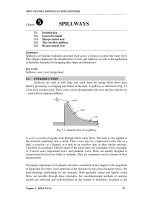
A typical gyroscope configuration is shown in Figure 2.1. The electrically driven rotor is
suspended in a pair of precision low-friction bearings at either end of the rotor axle. The rotor
bearings are in turn supported by a circular ring, known as the inner gimbal ring; this inner gimbal
ring pivots on a second set of bearings that attach it to the outer gimbal ring. This pivoting action
of the inner gimbal defines the horizontal axis of the gyro, which is perpendicular to the spin axis of
the rotor as shown in Figure 2.1. The outer gimbal ring is attached to the instrument frame by a third
set of bearings that define the vertical axis of the gyro. The vertical axis is perpendicular to both the
horizontal axis and the spin axis.
Notice that if this configuration is oriented such that the spin axis points east-west, the horizontal
axis is aligned with the north-south meridian. Since the gyro is space-stable (i.e., fixed in the inertial
reference frame), the horizontal axis thus reads the horizontal earth rate component of the planet’s
rotation, while the vertical axis reads the vertical earth rate component. If the spin axis is rotated 90
degrees to a north-south alignment, the earth’s rotation does not affect the gyro’s horizontal axis,
since that axis is now orthogonal to the horizontal earth rate component.
Outer gimbal
Wheel bearing
Wheel
Inner gimbal
Outer pivot
Inner pivot
32 Part I Sensors for Mobile Robot Positioning
Figure 2.1:
Typical two-axis mechanical gyroscope configuration [Everett, 1995].
2.1.2 Gyrocompasses
The gyrocompass is a special configuration of the rate integrating gyroscope, employing a gravity
reference to implement a north-seeking function that can be used as a true-north navigation
reference. This phenomenon, first demonstrated in the early 1800s by Leon Foucault, was patented
in Germany by Herman Anschutz-Kaempfe in 1903, and in the U.S. by Elmer Sperry in 1908 [Carter,
1966]. The U.S. and German navies had both introduced gyrocompasses into their fleets by 1911
[Martin, 1986].
The north-seeking capability of the gyrocompass is directly tied to the horizontal earth rate
component measured by the horizontal axis. As mentioned earlier, when the gyro spin axis is
oriented in a north-south direction, it is insensitive to the earth's rotation, and no tilting occurs. From
this it follows that if tilting is observed, the spin axis is no longer aligned with the meridian. The
direction and magnitude of the measured tilt are directly related to the direction and magnitude of
the misalignment between the spin axis and true north.
2.1.3 Commercially Available Mechanical Gyroscopes
Numerous mechanical gyroscopes are available on the market. Typically, these precision machined
gyros can cost between $10,000 and $100,000. Lower cost mechanical gyros are usually of lesser
quality in terms of drift rate and accuracy. Mechanical gyroscopes are rapidly being replaced by
modern high-precision — and recently — low-cost fiber-optic gyroscopes. For this reason we will
discuss only a few low-cost mechanical gyros, specifically those that may appeal to mobile robotics
hobbyists.
Chapter 2: Heading Sensors 33
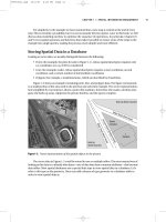
Figure 2.2: The Futaba FP-G154 miniature mechanical
gyroscope for radio-controlled helicopters. The unit costs
less than $150 and weighs only 102 g (3.6 oz).
Figure 2.3: The Gyration
GyroEngine
compares in size
favorably with a roll of 35 mm film (courtesy Gyration, Inc.).
2.1.3.1 Futaba Model Helicopter Gyro
The Futaba FP-G154 [FUTABA] is a low-
cost low-accuracy mechanical rate gyro
designed for use in radio-controlled model
helicopters and model airplanes. The Futaba
FP-G154 costs less than $150 and is avail-
able at hobby stores, for example [TOWER].
The unit comprises of the mechanical gyro-
scope (shown in Figure 2.2 with the cover
removed) and a small control amplifier.
Designed for weight-sensitive model helicop-
ters, the system weighs only 102 grams
(3.6 oz). Motor and amplifier run off a 5 V
DC supply and consume only 120 mA.
However, sensitivity and accuracy are orders
of magnitude lower than “professional”
mechanical gyroscopes. The drift of radio-control type gyroscopes is on the order of tens of degrees
per minute.
2.1.3.2 Gyration, Inc.
The GyroEngine made by Gyration, Inc.
[GYRATION], Saratoga, CA, is a low-cost
mechanical gyroscope that measures
changes in rotation around two independ-
ent axes. One of the original applications
for which the GyroEngine was designed is
the GyroPoint, a three-dimensional point-
ing device for manipulating a cursor in
three-dimensional computer graphics. The
GyroEngine model GE9300-C has a typi-
cal drift rate of about 9/min. It weighs
only 40 grams (1.5 oz) and compares in
size with that of a roll of 35 millimeter film
(see Figure 2.3). The sensor can be pow-
ered with 5 to 15 VDC and draws only 65
to 85 mA during operation. The open collector outputs can be readily interfaced with digital circuits.
A single GyroEngine unit costs $295.
2.2 Piezoelectric Gyroscopes
Piezoelectric vibrating gyroscopes use Coriolis forces to measure rate of rotation. in one typical
design three piezoelectric transducers are mounted on the three sides of a triangular prism. If one
of the transducers is excited at the transducer's resonance frequency (in the Gyrostar it is 8 kHz),
34 Part I Sensors for Mobile Robot Positioning
Figure 2.4: The Murata
Gyrostar
ENV-05H is a piezoelectric
vibrating gyroscope. (Courtesy of [Murata]).
the vibrations are picked up by the two other transducers at equal intensity. When the prism is
rotated around its longitudinal axis, the resulting Coriolis force will cause a slight difference in the
intensity of vibration of the two measuring transducers. The resulting analog voltage difference is
an output that varies linearly with the measured rate of rotation.
One popular piezoelectric vibrating gyroscope is the ENV-05 Gyrostar from [MURATA], shown
in Fig. 2.4. The Gyrostar is small, lightweight, and inexpensive: the model ENV-05H measures
47×40×22 mm (1.9×1.6×0.9 inches), weighs 42 grams (1.5 oz) and costs $300. The drift rate, as
quoted by the manufacturer, is very poor: 9/s. However, we believe that this number is the worst
case value, representative for extreme temperature changes in the working environment of the
sensor. When we tested a Gyrostar Model ENV-05H at the University of Michigan, we measured
drift rates under typical room temperatures of 0.05/s to 0.25/s, which equates to 3 to 15/min (see
[Borenstein and Feng, 1996]). Similar drift rates were reported by Barshan and Durrant-Whyte
[1995], who tested an earlier model: the Gyrostar ENV-05S (see Section 5.4.2.1 for more details on
this work). The scale factor, a measure for the useful sensitivity of the sensor, is quoted by the
manufacturer as 22.2 mV/deg/sec.
2.3 Optical Gyroscopes
Optical rotation sensors have now been under development as replacements for mechanical gyros
for over three decades. With little or no moving parts, such devices are virtually maintenance free
and display no gravitational sensitivities, eliminating the need for gimbals. Fueled by a large
EM field pattern
is stationary in
inertial frame
Observer moves
around ring
with rotation
Lossless
cylindrical
Nodes
mirror
Chapter 2: Heading Sensors 35
Figure 2.5: Standing wave created by counter-propagating light beams in
an idealized ring-laser gyro. (Adapted from [Schulz-DuBois, 1966].)
market in the automotive industry, highly linear fiber-optic versions are now evolving that have wide
dynamic range and very low projected costs.
The principle of operation of the optical gyroscope, first discussed by Sagnac [1913], is
conceptually very simple, although several significant engineering challenges had to be overcome
before practical application was possible. In fact, it was not until the demonstration of the helium-
neon laser at Bell Labs in 1960 that Sagnac’s discovery took on any serious implications; the first
operational ring-laser gyro was developed by Warren Macek of Sperry Corporation just two years
later [Martin, 1986]. Navigation quality ring-laser gyroscopes began routine service in inertial
navigation systems for the Boeing 757 and 767 in the early 1980s, and over half a million fiber-optic
navigation systems have been installed in Japanese automobiles since 1987 [Reunert, 1993]. Many
technological improvements since Macek’s first prototype make the optical rate gyro a potentially
significant influence on mobile robot navigation in the future.
The basic device consists of two laser beams traveling in opposite directions (i.e., counter
propagating) around a closed-loop path. The constructive and destructive interference patterns
formed by splitting off and mixing parts of the two beams can be used to determine the rate and
direction of rotation of the device itself.
Schulz-DuBois [1966] idealized the ring laser as a hollow doughnut-shaped mirror in which light
follows a closed circular path. Assuming an ideal 100-percent reflective mirror surface, the optical
energy inside the cavity is theoretically unaffected by any rotation of the mirror itself. The counter-
propagating light beams mutually reinforce each other to create a stationary standing wave of
intensity peaks and nulls as depicted in Figure 2.5, regardless of whether the gyro is rotating [Martin,
1986].
A simplistic visualization based on the Schulz-DuBois idealization is perhaps helpful at this point in
understanding the fundamental concept of operation before more detailed treatment of the subject
is presented. The light and dark fringes of the nodes are analogous to the reflective stripes or slotted
holes in the rotating disk of an incremental optical encoder, and can be theoretically counted in similar
fashion by a light detector mounted on the cavity wall. (In this analogy, however, the standing-wave
“disk” is fixed in the inertial reference frame, while the normally stationary detector revolves around
it.) With each full rotation of the mirrored doughnut, the detector would see a number of node peaks
equal to twice the optical path length of the beams divided by the wavelength of the light.
L
4%r
2
6
c
36 Part I Sensors for Mobile Robot Positioning
(2.2)
Obviously, there is no practical way to implement this theoretical arrangement, since a perfect
mirror cannot be realized in practice. Furthermore, the introduction of light energy into the cavity
(as well as the need to observe and count the nodes on the standing wave) would interfere with the
mirror's performance, should such an ideal capability even exist. However, many practical
embodiments of optical rotation sensors have been developed for use as rate gyros in navigation
applications. Five general configurations will be discussed in the following subsections:
Active optical resonators (2.3.1).
Passive optical resonators (2.3.2).
Open-loop fiber-optic interferometers (analog) (2.3.3).
Closed-loop fiber-optic interferometers (digital) (2.3.4).
Fiber-optic resonators (2.3.5).
Aronowitz [1971], Menegozzi and Lamb [1973], Chow et al. [1985], Wilkinson [1987], and Udd
[1991] provide in-depth discussions of the theory of the ring-laser gyro and its fiber-optic
derivatives. A comprehensive treatment of the technologies and an extensive bibliography of
preceding works is presented by Ezekial and Arditty [1982] in the proceedings of the First
International Conference on Fiber-Optic Rotation Sensors held at MIT in November, 1981. An
excellent treatment of the salient features, advantages, and disadvantages of ring laser gyros versus
fiber optic gyros is presented by Udd [1985, 1991].
2.3.1 Active Ring Laser Gyros
The active optical resonator configuration, more commonly known as the ring laser gyro, solves the
problem of introducing light into the doughnut by filling the cavity itself with an active lazing
medium, typically helium-neon. There are actually two beams generated by the laser, which travel
around the ring in opposite directions. If the gyro cavity is caused to physically rotate in the
counterclockwise direction, the counterclockwise propagating beam will be forced to traverse a
slightly longer path than under stationary conditions. Similarly, the clockwise propagating beam will
see its closed-loop path shortened by an identical amount. This phenomenon, known as the Sagnac
effect, in essence changes the length of the resonant cavity. The magnitude of this change is given
by the following equation [Chow et al., 1985]:
where
L = change in path length
r = radius of the circular beam path
6 = angular velocity of rotation
c = speed of light.
Note that the change in path length is directly proportional to the rotation rate 6 of the cavity.
Thus, to measure gyro rotation, some convenient means must be established to measure the induced
change in the optical path length.
This requirement to measure the difference in path lengths is where the invention of the laser in
the early 1960s provided the needed technological breakthrough that allowed Sagnac’s observations
to be put to practical use. For lazing to occur in the resonant cavity, the round-trip beam path must
f
2fr6
c
2r6
f
4A6
P
Chapter 2: Heading Sensors 37
(2.3)
(2.4)
be precisely equal in length to an integral number of wavelengths at the resonant frequency. This
means the wavelengths (and therefore the frequencies) of the two counter- propagating beams must
change, as only oscillations with wavelengths satisfying the resonance condition can be sustained
in the cavity. The frequency difference between the two beams is given by [Chow et al., 1985]:
where
f = frequency difference
r = radius of circular beam path
6 = angular velocity of rotation
= wavelength.
In practice, a doughnut-shaped ring cavity would be hard to realize. For an arbitrary cavity
geometry, the expression becomes [Chow et al., 1985]:
where
f = frequency difference
A = area enclosed by the closed-loop beam path
6 = angular velocity of rotation
P = perimeter of the beam path
= wavelength.
For single-axis gyros, the ring is generally formed by aligning three highly reflective mirrors to
create a closed-loop triangular path as shown in Figure 2.6. (Some systems, such as Macek’s early
prototype, employ four mirrors to create a square path.) The mirrors are usually mounted to a
monolithic glass-ceramic block with machined ports for the cavity bores and electrodes. Most
modern three-axis units employ a square block cube with a total of six mirrors, each mounted to the
center of a block face as shown in Figure 2.6. The most stable systems employ linearly polarized light
and minimize circularly polarized components to avoid magnetic sensitivities [Martin, 1986].
The approximate quantum noise limit for the ring-laser gyro is due to spontaneous emission in the
gain medium [Ezekiel and Arditty, 1982]. Yet, the ring-laser gyro represents the “best-case” scenario
of the five general gyro configurations outlined above. For this reason the active ring-laser gyro
offers the highest sensitivity and is perhaps the most accurate implementation to date.
The fundamental disadvantage associated with the active ring laser is a problem called frequency
lock-in, which occurs at low rotation rates when the counter-propagating beams “lock” together in
frequency [Chao et al., 1984]. This lock-in is attributed to the influence of a very small amount of
backscatter from the mirror surfaces, and results in a deadband region (below a certain threshold of
rotational velocity) for which there is no output signal. Above the lock-in threshold, output
approaches the ideal linear response curve in a parabolic fashion.
The most obvious approach to solving the lock-in problem is to improve the quality of the mirrors
to reduce the resulting backscatter. Again, however, perfect mirrors do not exist, and some finite
B
CD
A
38 Part I Sensors for Mobile Robot Positioning
Figure 2.6: Six-mirror configuration of three-axis ring-laser
gyro. (Adapted from [Koper, 1987].)
amount of backscatter will always be present. Martin [1986] reports a representative value as 10
-12
of the power of the main beam; enough to induce frequency lock-in for rotational rates of several
hundred degrees per hour in a typical gyro with a 20-centimeter (8-in) perimeter.
An additional technique for reducing lock-in is to incorporate some type of biasing scheme to shift
the operating point away from the deadband zone. Mechanical dithering is the least elegant but most
common biasing means, introducing the obvious disadvantages of increased system complexity and
reduced mean time between failures due to the moving parts. The entire gyro assembly is rotated
back and forth about the sensing axis in an oscillatory fashion. State-of-the-art dithered active ring
laser gyros have a scale factor linearity that far surpasses the best mechanical gyros.
Dithered biasing, unfortunately, is too slow for high-performance systems (i.e., flight control),
resulting in oscillatory instabilities [Martin, 1986]. Furthermore, mechanical dithering can introduce
crosstalk between axes on a multi-axis system, although some unibody three-axis gyros employ a
common dither axis to eliminate this possibility [Martin, 1986].
Buholz and Chodorow [1967], Chesnoy [1989], and Christian and Rosker [1991] discuss the use
of extremely short duration laser pulses (typically 1/15 of the resonator perimeter in length) to
reduce the effects of frequency lock-in at low rotation rates. The basic idea is to reduce the cross-
coupling between the two counter-propagating beams by limiting the regions in the cavity where the
two pulses overlap. Wax and Chodorow [1972] report an improvement in performance of two orders
of magnitude through the use of intracavity phase modulation. Other techniques based on non-linear
optics have been proposed, including an approach by Litton that applies an external magnetic field
to the cavity to create a directionally dependent phase shift for biasing [Martin, 1986]. Yet another
solution to the lock-in problem is to remove the lazing medium from the ring altogether, effectively
forming what is known as a passive ring resonator.