Tài liệu Industrial Automation Wiring and Grounding Guidelines pdf
Bạn đang xem bản rút gọn của tài liệu. Xem và tải ngay bản đầy đủ của tài liệu tại đây (267.37 KB, 20 trang )
Publication 1770-4.1 – February 1998
Industrial Automation Wiring and
Grounding Guidelines
This publication gives you general guidelines for installing an
Allen-Bradley industrial automation system that may include
programmable controllers, industrial computers, operator-interface
terminals, display devices, and communication networks. While
these guidelines apply to the majority of installations, certain
electrically harsh environments may require additional
precautions.
Use these guidelines as a tool for helping avoid potential
electromagnetic interference (emi) and transient emi that could cause
problems such as “adapter faults, rack faults, communication faults,”
etc. These guidelines are not intended to supersede local electrical
codes.
This publication is organized into the following sections:
•
Raceway layout considerations
•
Mounting, bonding, and grounding
•
Power distribution
•
Surge-suppression
•
Ferrite beads
•
Enclosure lighting
•
Avoiding unintentional momentary turn-on of outputs
•
Related publications
Application Data
Purpose
Industrial Automation Wiring and Grounding Guidelines2
Publication
1770-4.1 – February 1998
The raceway layout of a system is reflective of where the different
types of I/O modules are placed in I/O chassis. Therefore, you
should determine I/O-module placement prior to any layout and
routing of wires. However, when planning your I/O-module
placement, segregate the modules based upon the conductor
categories published for each I/O module so that you can follow
these guidelines. Also, all conductors (ac or dc) in the same raceway
must be insulated for the highest voltage applied to any one of the
conductors in the raceway. These guidelines coincide with the
guidelines for “the installation of electrical equipment to minimize
electrical noise inputs to controllers from external sources” in IEEE
standard 518-1982.
Categorize Conductors
Segregate all wires and cables into the following three categories
(Table A). Refer to the publication for each specific I/O module or
block for individual conductor-category classification of each I/O
line.
Table A
Follow these Guidelines for Grouping Conductors with
Respect to Noise
Group conductor cables fitting this description
Into this
category:
Examples:
Control & ac Power — high-power conductors that are
more tolerant of electrical noise than category 2
conductors
and may also cause more noise to be picked
up by adjacent conductors
•
corresponds to IEEE levels 3 (low susceptibility) &
4 (power)
Category 1
•
ac power lines for power supplies and I/O circuits.
•
high-power digital ac I/O lines — to connect ac I/O modules rated for
high power and high noise immunity
•
high-power digital dc I/O lines — to connect dc I/O modules rated for
high power or with input circuits with long time-constant filters for high
noise rejection. They typically connect devices such as hard-contact
switches, relays, and solenoids.
Signal & Communication — low-power conductors that
are less tolerant of electrical noise than category-1
conductors and should also cause less noise to be
picked up by adjacent conductors (they connect to
sensors and actuators relatively close to the I/O
modules)
•
corresponds to IEEE levels 1 (high susceptibility) &
2 (medium susceptibility)
Category 2
•
analog I/O lines and dc power lines for analog circuits
•
low-power digital ac/dc I/O lines — to connect to I/O modules that
are
rated for low power such as low-power contact-output modules
•
low-power digital dc I/O lines — to connect to dc I/O modules that are
rated for low power and have input circuits with short time-constant
filters to detect short pulses. They typically connect to devices such as
proximity switches, photo-electric sensors, TTL devices, and encoders
•
communication cables (ControlNet
t
, DeviceNet
t
, Universal remote
I/O, extended-local I/O, DH+
, DH-485, RS-232-C, RS-422, RS-423
cables) — to connect between processors or to I/O adapter modules,
programming terminals, computers, or data terminals
Intra-enclosure
— interconnect
the system components
within an enclosure
•
corresponds to IEEE levels 1 (high susceptibility) &
2 (medium susceptibility)
Category 3
•
low-voltage dc power cables — provide backplane power to the
system components
•
communication cables — to connect between system components
within the same enclosure
NOTE:
Remote I/O and DH+ cables must be made of catalog number 1770-CD cable or a cable from the approved-vendor list (publication ICCG-2.2).
DH-485 cables must be made of a cable from the approved-vendor list in publication 1770-6.2.2.
Raceway Layout
Considerations
Industrial Automation Wiring and Grounding Guidelines 3
Publication
1770-4.1 – February 1998
Route Conductors
To guard against coupling noise from one conductor to another,
follow these general guidelines (Table B) when routing wires and
cables (both inside and outside of an enclosure). Use the spacing
given in these general guidelines with the following exceptions:
•
where connection points (for conductors of different categories)
on a device are closer together than the specified spacing
•
application-specific configurations for which the spacing is
described in a publication for that specific application
These guidelines are for noise immunity only. Follow all local
codes for safety requirements.
Table B
Follow these Guidelines for Routing Cables to Guard
Against Noise
Route this category
of conductor cables:
According to these guidelines:
Category 1 These conductors can be routed in the same cable tray or raceway with machine power conductors of up to 600V ac
(feeding up to 100 hp devices).
Category 2
•
If it must cross power feed lines, it should do so at right angles.
•
Route at least 5 ft from high-voltage enclosures, or sources of rf/microwave radiation.
•
If the conductor is in a metal wireway or conduit, each segment of that wireway or conduit must be bonded to each
adjacent segment so that it has electrical continuity along its entire length, and must be bonded to the enclosure at the
entry point.
•
Properly shield (where applicable) and route in a raceway separate from category-1 conductors.
•
If
in a contiguous metallic wireway or conduit, route at least 0.08m (3 in) from category-1 conductors of less than
20A;
0.15m (6 in) from ac power lines of 20A or more, but only up to 100 kV
A; 0.3m (1 ft) from ac power lines of greater
than 100 kVA.
•
If
not in a contiguous metallic wireway or conduit, route at least 0.15m (6 in) from category-1 conductors of less
than 20A; 0.3m (1 ft) from ac power lines of 20A or more, but only up to 100 kVA; 0.6m (2 ft) from ac power lines of
greater than 100 kVA.
Category 3 Route conductors external to all raceways in the enclosure or in a raceway separate from any category-1 conductors with
the same spacing listed for category-2 conductors, where possible.
Important: These guidelines assume that you follow the
surge-suppression guidelines (page 15). While these guidelines
apply to the majority of installations, certain electrically harsh
environments may require additional precautions.
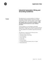
The use of the guidelines in Table B are illustrated in Figure 1.
Industrial Automation Wiring and Grounding Guidelines
4
Publication
1770-4.1 – February 1998
Figure 1
Mounting Assembly Details
Category-2
Conductors
Enclosure Wall
12618-I
I/O Block
Transformer
Use greater
spacing without
conduit
Tighter spacing
allowed
with conduit
Tighter spacing allowed
where forced by spacing
of connection points
Place modules to
comply with spacing
guidelines if possible
Category-1
Conductors
(ac Power Lines)
Category-2
Conductors
Conduit
1771 I/O Chassis
Conduit
After establishing all layouts, you can begin mounting, bonding, and
grounding each chassis. Bonding is the connecting together of metal
parts of chassis, assemblies, frames, shields, and enclosures to
reduce the effects of emi and ground noise. Grounding is the
connection to the grounding-electrode system to place equipment at
earth ground potential.
Mounting, Bonding, and
Grounding
Industrial Automation Wiring and Grounding Guidelines 5
Publication
1770-4.1 – February 1998
Mounting and Bonding the Chassis
You can mount the chassis with either bolts or welded studs.
Figure 2 shows details for:
•
stud-mounting a ground bus or chassis to the back panel of the
enclosure
•
stud-mounting a back panel to the enclosure
•
bolt-mounting a ground bus or chassis to the back panel of the
enclosure
If the mounting brackets of a chassis do not lay flat before the nuts
are tightened, use additional washers as shims so that the chassis
does not bend when you tighten the nuts.
Important: Do not bend the chassis. Bending the chassis might
damage the backplane and result in poor connections.
Figure 2
Mounting Assembly Details
If the mounting bracket is coated
with a non-conductive material
(anodized, painted, etc.), scrape
the material around the mounting
hole.
Bolt mounting of a ground bus or chassis to the back panel
Stud mounting of the back panel to the enclosure back wall
Stud mounting of a ground bus or chassis to the back panel
If the mounting bracket is coated
with a non-conductive material
(anodized, painted, etc.), scrape
the material around the
mounting hole.
Bolt
Tapped
Hole
Back Panel
Ground Bus or
Mounting Bracket
Back Panel
Nut
17664
17665
Nut
Nut
Back Panel
Welded Stud
Scrape paint
17666
Nut
If the mounting bracket is coated with
a non-conductive material (anodized,
painted, etc.), scrape the material
around the mounting hole.
Alternative bolt mounting of chassis to the back panel
Mounting Bracket
Star
Washer
Flat
Washer
Back Panel
Scrape paint
12342-I
Bolt
Tapped Hole
Use a wire brush to remove
paint from threads to allow a
ground connection.
Scrape
paint on panel and
use a star washer.
Scrape
paint on
panel
and
use star washers.
Welded
Stud
Back Wall of
Enclosure
Mounting Bracket
or Ground Bus
Flat
Washer
Star
Washer
Star
Washer
Flat
Washer
Flat
Washer
Flat
Washer
Flat
Washer
Industrial Automation Wiring and Grounding Guidelines6
Publication
1770-4.1 – February 1998
Make good electrical connection between each chassis, back-panel,
and enclosure through each mounting bolt or stud. Wherever contact
is made, remove paint or other non-conductive finish from around
studs or tapped holes.
Bonding and Grounding the Chassis
With solid-state controls, proper bonding and grounding helps
reduce the effects of emi and ground noise. Also, since bonding and
grounding are important for safety in electrical installations, local
codes and ordinances dictate which bonding and grounding methods
are permissible.
For example, for U.S. installations, the National Electrical Code
(NEC) gives you the requirements for safe bonding and grounding,
such as information about the size and types of conductors and
methods of safely grounding electrical components.
Equipment-Grounding Conductor — In addition to making good
connections through each bolt or stud, use either 1-inch copper braid
or 8 AWG minimum stranded copper wire to connect each chassis,
enclosure and central ground bus mounted on the back-panel. Figure
3 shows ground-bus connection details.
Figure 3
Ground Bus Connection Details
Equipment-
13271
grounding
Conductors
Ground
Lug
Bolt
Star
Washer
Ground Bus
Mounting
Ground Bus
Tapped Hole
Grounding-electrode conductor
to grounding-electrode system.
Figure 4 shows enclosure-wall ground connection details. Use a
steel enclosure to guard against emi. If the enclosure door has a
viewing window, it should be a laminated screen or a conductive
optical substrate to block emi. Do not rely on the hinge for electrical
contact between the door and the enclosure; install a bonding wire.
Industrial Automation Wiring and Grounding Guidelines 7
Publication
1770-4.1 – February 1998
Figure 4
Details of Ground Connection at Enclosure Wall
and use a star washer.
10020
Enclosure
Wall
Scrape
Paint
Bolt
Scrape paint on enclosure wall
Ground
Lug
Nut
Star
Washer
Equipment-
Grounding
Conductor
Connect an equipment grounding conductor directly from each
chassis to an individual bolt on the ground bus. For a chassis with
no ground stud, use a mounting bolt (Figure 5). For those chassis
with a ground stud, use the ground stud for this connection
(Figure 6).
Figure 5
Details of Ground Connection at Mounting Bracket of
Chassis with No Ground Stud
If
the mounting bracket is coated with
a
non-conductive material (anodized,
painted, etc.), scrape the material
around the mounting hole.
Mounting Bracket
Nut
Back Panel
Welded Stud
Scrape paint
17666
Flat
Washer
Flat
Washer
Star
Washer
Ground
Lug
For a power supply without a groundable power supply chassis (such
as a power-supply module or mini-processor with an integral power
supply), or a power supply (such as the 1771–P7 or 1771–PS7) with
a chassis that is not internally connected to its GND terminal, use a
14 AWG copper wire to connect its GND terminal to the ground stud
or mounting bolt connected to the ground bus. This will ensure an
adequate ground for noise immunity.
Industrial Automation Wiring and Grounding Guidelines8
Publication
1770-4.1 – February 1998
Figure 6
Typical Grounding Configuration
Enclosure Wall
I/O Chassis Wall
Nut
Ground Lug
14 AWG
14 AWG
15317
See Figure 3
See Figure 4
FLEX I/O
Modules
DIN Rail
Star
Washer
Star
Washers
Ground
Lug
Ground
Bus
Mini-processor with
built-in power supply
Power-supply
module
Grounding-
electrode
Conductor
To Grounding-
electrode
System
Equipment-grounding
Conductors 8AWG
Ground
Bus
Equipment-grounding
Conductors 14AWG
1771 Chassis
with 2 Power
Supplies
1771 Chassis
with 1771-P7
Power Supply
1756 Chassis
with 1756-PA72
Power Supply
1771-P7
Power Supply
Do not lay one ground lug directly on top of the other. This type of
connection can become loose due to compression of the metal lugs.
Sandwich the first lug between a star washer and a nut with a captive
star washer. After tightening the nut, sandwich the second lug
between the first nut and a second nut with a captive star washer.