Tài liệu Characteristics of IREDs pptx
Bạn đang xem bản rút gọn của tài liệu. Xem và tải ngay bản đầy đủ của tài liệu tại đây (40.86 KB, 3 trang )
26
Characteristics of IREDs
Measurement of Power Output
It is standard industry practice to characterize the output of IREDs in
terms of power output. Since the amount of light an IRED generates
depends on the value of the forward drive current (I
F
), the power output
is always stated for a given value of current. Also, the ambient
temperature must be specified inasmuch as the radiant power
decreases with increasing temperature, power decreases with
increasing temperature, typically -0.9%/°C.
The following two methods are used to measure light power output.
Total Power (P
O
)
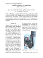
This method involves collecting and measuring the total amount of light
emitted from the IRED regardless of the direction. This measurement
is usually done by using an integrating sphere or by placing a very
large area detector directly in front of the IRED so that all light emitted
in the forward direction is collected. The total output power is
measured in units of watts.
The total power method ignores the effect of the beam pattern
produced by the IRED package. It cannot predict how much light will
strike an object positioned some distance in front of the IRED. This
information is vital for design calculations in many applications.
However, total output power measurement is repeatable and quite
useful when trying to compare the relative performance of devices in
the same type of package.
Measuring Total Power - All Light is Collected
On Axis Power (P
A
)
This method characterizes the IRED in terms of axial intensity. Many
practical applications require knowledge of what percentage of IR
power emitted is incident upon a detector located at some distance in
front of the IRED. In order to achieve repeatable and meaningful
measurement of this parameter it is necessary that the distance from
the IRED to the detector and the active area of the detector be
specified. This is because the radiation pattern observed for many
IREDs is dependent on the distance from the IRED.
For many of its emitters PerkinElmer Optoelectronics states a
minimum irradiance (E
e
), which is the average power density in
milliwatts per square centimeter (mw/cm
2
) incident onto a surface of
diameter (D) at a distance (d). The irradiance will in general not be
uniform over this whole surface, and may be more or less intense on
the optical axis. Irradiance at other distances may be determined from
the graphs showing irradiance versus distance.
The on-axis power can also be stated as a radiant intensity (I
e
) which
is the average power per unit of solid angle expressed in units of
milliwatts per steradian (mW/sr). To calculate the irradiance at any
distance the following formula is applicable.
E
e
= I
e
/d
2
(mW/cm
2
)
where:
I
e
= radiant intensity (mW/sr)
d = distance (cm)
However, it should be noted that the IRED cannot be treated as a point
source when the spacing between the IRED and receiver is small, less
than ten times the IRED package diameter. Attempts to use the inverse
square law can lead to serious errors when the detector is close to the
IRED. Actual measurements should be used in this situation.
For IREDs of any particular package type there is a direct relationship
between all three methods used for specifying power output. However,
imperfect physical packages and optical aberrations prevent perfect
correlation.
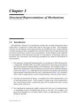
Measuring On-Axis Power
Detector is so large in area
and is so close to the IRED
that all light emitted by the
IRED is collected.
Detector or area (A) is located at
specified distance (d) in front of the
IRED being measured.
27
Characteristics of IREDs
Efficiency vs. Drive Current
As mentioned in the section What is an LED? What is an IRED?, once
injected carriers cross the junction they can recombine by a radiative
process which produces light or by a nonradiative process which
produces heat. The ratio between these two processes is dependent
on the current density (Amps/cm
2
of junction area).
At low current densities (.1A/cm
2
) the nonradiative processes
dominate and very little light is generated. As the current density is
increased the radiative mechanisms increase in efficiency so that a
larger and larger percentage of the forward current will contribute to
the generation of light. At sufficient current densities, the percentage of
forward current which produces light is almost a constant. For an IRED
of “average” junction area (0.015" x 0.015") this region of linear
operation is in the range of approximately 2 mA to 100 mA. Also, at
high forward drive currents the junction temperature of the chip
increases due to significant power dissipation. This rise in temperature
results in a decrease in the radiative recombination efficiency. As the
current density is further increased, internal series resistance effects
will also tend to reduce the light generating efficiency of the IRED.
Light Output Degradation
In normal operation, the amount of light produced by an IRED will
gradually decrease with time. The rate of decrease depends on the
temperature and the current density. IREDs driven at low forward
currents at room temperature ambient will degrade more slowly than
IREDs driven at higher forward drive currents and at elevated
temperatures. Typical degradation data is presented in the data sheet
section.
Light output degradation is caused by stress placed on the IRED chip,
be it mechanical, thermal or electrical. Stress causes defects in the
chip to propagate along the planes of the chip’s crystalline structure.
These defects in the crystalline structure, called dark line defects,
increase the percentage of non radiative recombinations. Forward
biasing the IRED provides energy which aids in the formation and
propagation of these defects. The designer using IREDs must address
the light output degradation with time characteristic by including
adequate degradation margins in his design so that it will continue to
function adequately to the end of the design life.
Peak Spectral Wavelength (λ
P
)
IREDs are commonly considered to emit monochromatic light, or light
of one color. In fact, they emit light over a narrow band of wavelengths,
typically less than 100 nm.
The wavelength at which the greatest amount of light is generated is
called the peak wavelength,
λ
P
. It is determined by the energy
bandgap of the semiconductor material used and the type of dopants
incorporated into the IRED. The peak wavelength is a function of
temperature. As the temperature increases,
λ
P
shifts towards longer
wavelengths (typically 0.2 nm/°C).
Forward Voltage (V
F
)
The current-voltage characteristics of IREDs, like any other PN
junction device, obeys the standard diode equation.
V
F
is the voltage drop across the IRED when it is forward biased at a
specific current, I
F
. It is important to note that V
F
is a function of
temperature, decreasing as temperature increases. Plots of V
F
vs. I
F
as a function of temperature are included in the data sheet section.
Reverse Breakdown Voltage (V
BR
)
This is the maximum reverse voltage that can safely be applied across
the IRED before breakdown occurs at the junction. The IRED should
never be exposed to V
BR
even for a short period of time since
permanent damage can occur. PerkinElmer IREDs are tested to a
reverse voltage specification of 5V minimum.
I
F
I
O
e
qV
F
nKT⁄
1–[]=
28
Characterizations of IREDs
Power Dissipation
Current flow through an IRED is accompanied by a voltage drop
across the device. The power dissipated (power = current x voltage)
causes a rise in the junction temperature rise is a decrease in the light
output of the IRED (approximately -0.9%/°C). If the junction
temperature becomes too high, permanent damage to the IRED will
result. The maximum power dissipation rating of a semiconductor
device defines that operating region where overheating can damage
the device.
In any practical application, the maximum power dissipation depends
on: ambient temperature, maximum (safe) junction temperature, the
type of IRED package, how the IRED package is mounted, and the
exact electrical drive current parameters.
While the IRED chip generates heat, its packaging serves to remove
this heat out into the environment. The package’s ability to dissipate
heat depends not only on its design and construction but also varies
from a maximum, if an efficient infinite heat sink is used, to a minimum,
for the case where no heat sink is present.
The thermal impedance rating of the package quantifies the package’s
ability to get rid of the heat generated by the IRED chip under normal
operation.
Thermal impedance is defined as:
θ
JA
= (T
J
– T
A
) / P
D
°C/W
where:
θ
JA
= thermal impedance, junction to ambient
T
J
= junction temperature
T
A
= ambient temperature
P
D
= power dissipation of the device
By definition
θ
JA
assumes that the device is not connected to an
external heat sink and as such represents a worse case condition in as
far as power dissipation is concerned.
For plastic packages and non-heat-sunk hermetics:
θ
JA
≡
400°C/W
Example: A hermetic LED is driven with a forward current of 20 mA dc.
At this drive current the forward voltage drop across the IRED is 1.5
volts.
P
D
= (.020 A) x (1.5 V) = .030 W
∆
T = (400°C/W) x (.030 W) = 12°C
(–0.9%/°C) x 12°C)
≅
-11%
There is an 11% decrease in the amount of light generated by the
IRED.
For hermetics with good heat sinking:
θ
JC
≅
150°C/W
where:
θ
JC
= thermal impedance, junction to case
∆
T = (150°C/W) x (.030 W) = 4.5°C
(–0.9%/°C) x (4.5°C)
≅
-4%
There is only a 4% decrease in the amount of light generated by the
IRED when a heat sink is used.
This is a clear example of the law of diminishing returns: increasing the
forward drive current will increase the amount of light generated by the
IRED. However, increasing the drive current also increases the power
dissipation in the device. This raises the IRED’s junction temperature
resulting in a decrease in the IRED’s efficiency.
One way to overcome this performance limiting characteristic is to
pulse the IRED on and off rather than driving it with a dc current.
Maximum light output is obtained because the average power
dissipated is kept small. Above 100 mA of drive current it is advisable
to limit the maximum pulse width to a few hundred microsecounds, and
a 10% duty cycle.