Tài liệu The Devices - Jan M. Rabaey ( Các thiết bị - tác giả Jan M.Rabaey ) pptx
Bạn đang xem bản rút gọn của tài liệu. Xem và tải ngay bản đầy đủ của tài liệu tại đây (889.24 KB, 49 trang )
Jan M. Rabaey
The Devices
Digital Integrated Circuits © Prentice Hall 1995
Introduction
Introduction
Goal of this chapter
• Present intuitive understanding of device operation
• Introduction of basic device equations
• Introduction of models for manual analysis
• Introduction of models for SPICE simulation
• Analysis of secondary and deep-sub-micron
effects
• Future trends
Digital Integrated Circuits © Prentice Hall 1995
Introduction
Introduction
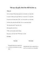
The Diode
n
p
p
n
B A
SiO
2
Al
A
B
Al
A
B
Cross-section of pn-junction in an IC process
One-dimensional
representation diode symbol
Digital Integrated Circuits © Prentice Hall 1995
Introduction
Introduction
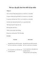
Depletion Region
hole diffusion
electron diffusion
p n
hole drift
electron drift
Charge
Density
Distance
x+
-
Electrical
x
Field
x
Potential
V
ξ
ρ
W
2
-W
1
ψ
0
(a) Current flow.
(b) Charge density.
(c) Electric field.
(d) Electrostatic
potential.
Digital Integrated Circuits © Prentice Hall 1995
Introduction
Introduction
Diode Current
Digital Integrated Circuits © Prentice Hall 1995
Introduction
Introduction
Models for Manual Analysis
V
D
I
D
= I
S
(e
V
D
/
φ
T
– 1)
+
–
V
D
+
–
+
–
V
Don
I
D
(a) Ideal diode model (b) First-order diode model
Digital Integrated Circuits © Prentice Hall 1995
Introduction
Introduction
Junction Capacitance
Digital Integrated Circuits © Prentice Hall 1995
Introduction
Introduction
Diode Switching Time
V
src
t = 0
V
1
V
2
V
D
R
src
t = T
I
D
Time
V
D
ON
OFF
ON
Space charge
Excess charge
Digital Integrated Circuits © Prentice Hall 1995
Introduction
Introduction
Secondary Effects
–25.0 –15.0 –5.0 5.0
V
D
(V)
–0.1
I
D
(A)
0.1
0
0
Avalanche Breakdown
Digital Integrated Circuits © Prentice Hall 1995
Introduction
Introduction
Diode Model
I
D
R
S
C
D
+
-
V
D
Digital Integrated Circuits © Prentice Hall 1995
Introduction
Introduction
SPICE Parameters
Digital Integrated Circuits © Prentice Hall 1995
Introduction
Introduction
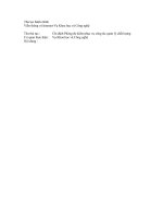
The MOS Transistor
n+n+
p-substrate
Field-Oxyde
(SiO
2
)
p+ stopper
Polysilicon
Gate Oxyde
Drain
Source
Gate
Bulk Contact
CROSS-SECTION of NMOS Transistor
Digital Integrated Circuits © Prentice Hall 1995
Introduction
Introduction
Cross-Section of CMOS
Technology
Digital Integrated Circuits © Prentice Hall 1995
Introduction
Introduction
MOS transistors
Types and Symbols
D
S
G
D
S
G
G
S
D D
S
G
NMOS
Enhancement
NMOS
PMOS
Depletion
Enhancement
B
NMOS with
Bulk Contact
Digital Integrated Circuits © Prentice Hall 1995
Introduction
Introduction
n+n+
p-substrate
Field-Oxyde
(SiO
2
)
p+ stopper
Polysilicon
Gate Oxyde
Drain
Source
Gate
Bulk Contact
CROSS-SECTION of NMOS Transistor
Transistor: No Voltages
Digital Integrated Circuits © Prentice Hall 1995
Introduction
Introduction
Introduction to VLSI Design © Steven P. Levitan 1998
Introduction
Introduction
Transistor “Off” V
gs
<V
t
V
gd
V
gs
I
ds
V
ds
I=V/R
No Channel exists:
Enhancement mode transistor
R
n+n+
p-substrate
D
S
G
B
V
GS
+
-
Depletion
Region
n-channel
V
ds
does not matter
I
ds
Threshold Voltage: Concept
n+n+
p-substrate
D
S
G
B
V
GS
+
-
Depletion
Region
n-channel
Digital Integrated Circuits © Prentice Hall 1995
Introduction
Introduction
The Threshold Voltage
Digital Integrated Circuits © Prentice Hall 1995
Introduction
Introduction
GND
Out
?
A
B
Body Effect
Introduction to VLSI Design © Steven P. Levitan 1998
Introduction
Introduction
n+n+
p-substrate
D
S
G
B
V
GS
+
-
Depletion
Region
n-channel
Channel Formation V
gs
>V
t
V
gd
V
gs
I
ds
V
ds
I=V/R
Positive Charge on Gate:
Channel exists, but no current
since V
ds
= 0
R
I
ds