Tài liệu Evolution of GSM and cdmaOne to 3G Systems pptx
Bạn đang xem bản rút gọn của tài liệu. Xem và tải ngay bản đầy đủ của tài liệu tại đây (970.79 KB, 100 trang )
Chapter 6
Evolution of GSM and cdmaOne to
3G Systems.
Chapter
6
Evolution of GSM and cdmaOne to
3G Systems
6.1 Introduction
The previous chapters have concentrated on the two leading second generation (2G) cellular
systems: GSM and IS-95. These systems are deployed in many parts of the world and will
continue to operate and evolve during the next decade as third generation (3G) systems are
rolled out. We may expect that the new 3G systems will be harmonised with their evolved
2G counterparts, and that slowly 2G spectra will be refarmed to provide extra 3G spectra.
No 3G systems are currently deployed, although trials are in progress. As a consequence,
this chapter, which deals with systems that are about to be deployed, is treated in a qual-
itative manner, describing how they will work rather than quantifying their performances.
Before getting into detail, let us briefly review how cellular communications arrived at to-
day’s position.
6.1.1 The generation game
There is no doubt that there was pent-up demand for public mobile telephony networks,
and when they arrived in the 1980s as the so-called first generation (1G) analogue cellular
networks, they grew at phenomenal rates. These networks initially offered only telephony,
but the un-tethering of people from their fixed phones meant that they and businesses could
operate in completely new ways. The Europeans identified in the early 1980s the need for a
second generation (2G) cellular system that would be totally digital. This 2G system became
GSM, and a brief history of GSM has already been provided in Section 2.1. The Europeans
have a long view in cellular radio and in 1988 they launched their RACE 1043 project with
404
GSM, cdmaOne and 3G Systems. Raymond Steele, Chin-Chun Lee and Peter Gould
Copyright © 2001 John Wiley & Sons Ltd
Print ISBN 0-471-49185-3 Electronic ISBN 0-470-84167-2
6.1. INTRODUCTION
405
the aim of identifying the services and technologies for an advanced third generation (3G)
system for deployment by the year 2000 [1, 2]. Their 3G system soon became known as
the universal mobile telecommunications system (UMTS) [3–5]. The concept was that their
1G, 2G and 3G systems would be independent, and that their deployment would overlap
such that the total access communications system (TACS), say, would slowly be replaced
by GSM, which in turn would be slowly phased out for UMTS. However, the success of
GSM has been so great that evolutionary paths from 2G to 3G needed to be considered.
Although the back-haul networks of GSM and UMTS have considerable commonality, their
radio interfaces are significantly different.
There were initially great expectations for UMTS [5,6]. It would not only be cellular, but
it would embrace other types of networks from private mobile radio (PMR) (called special
mobile radio (SMR) in the United States), to wireless local area networks (WLANs), to
mobile satellite systems (MSSs). The cardinal points were that it would operate globally,
support high bit rate services and, most importantly, be service orientated. While the Eu-
ropeans referred to the global 3G network for the turn of the century as UMTS, most of
their engineers working on UMTS expected that they would have to yield to international
agreements from the ITU to modify UMTS, but that basically UMTS would be accepted as
the global standard.
To explain this early expectation we need to point out that the ITU has been in the 3G
game from the beginning [6]. Paralleling the European Union (EU) RACE initiative, ITU
formed task group TG8/1, originally under the auspices of CCIR. This committee referred
to their 3G system as the future public land mobile telecommunications system (FPLMTS).
Europeans were, of course, also members of TG8/1, and with commercial and political pres-
sures a long way in the future, FPLMTS and UMTS seemed synonymous in terms of aims
and objectives. The important difference between TG8/1 and the happenings in Europe,
was that in Europe there was an actual research and development (R&D) 3G programme in
process, while TG8/1 was more like a forum.
The Americans did not launch concerted national R&D programmes, neither for 2G nor
3G systems. Their advanced mobile phone service (AMPS) 1G system did evolve into the
2G IS-136, and became dual-mode with IS-95. The United States also introduced the iDEN
system with its ability to offer both cellular and dispatch services. It then auctioned a large
part of its 3G spectrum for PCS licenses, and allowed GSM to enter the United States in
the form of PCS1900. This auctioning of the 3G spectrum meant that there were significant
advantages if existing 2G networks could evolve into 3G ones, preferably in a seamless
manner.
A big factor, not just in the United States, but in the world, was the advent of IS-95 [7–11].
It arrived late compared with GSM, and some engineers argued that it was a 2.5G system.
It had to fight to be born because of the lack of spectrum, and the quasi-religious attitudes
406
CHAPTER 6. EVOLUTION OF GSM AND CDMAONE TO 3G SYSTEMS
of engineers towards methods of multiple access. The meagre spectrum of 1.25 MHz at the
top of the AMPS band was just about adequate for cellular CDMA, which was just as well
because that was all there was available. CDMA entered the cellular world with a host of
technical problems, not made easier as the transceivers from day one had to be dual-mode
with AMPS. Its advocates were clear in that CDMA has a high spectral efficiency and is
well suited to the 3G multiservice environment. The real significance of IS-95 is that it won
the technical argument in that the UMTS and the Japanese Association of Radio Industries
and Businesses (ARIB) proposals have CDMA radio interfaces, albeit of wider bandwidth
systems as more bandwidth is available for 3G networks. We therefore agree that IS-95 is a
2.5G system and its evolution to 3G should be smooth. This is not so for 2G TDMA systems
which will need to migrate to 3G CDMA ones. However, as we will show in Section 6.2,
GSM with its TDMA is able to evolve closely to 3G without picking up the CDMA card.
Nevertheless there is an evolutionary route from GSM Phase 2+ to UMTS as discussed in
Section 6.2
The TG8/1 Committee discarded the unwieldy FPLMTS name for its 3G system, and
replaced it with international mobile telecommunications for the year 2000, or simply IMT-
2000. It then abandoned all hope of the difficult political objective of a single standard,
and has instead opted for a family of standards. Each member of the family had to be
able to meet a minimum specification. Sixteen proposals were accepted, ten for terrestrial
3G networks, and six for MSSs. The majority of the proposals advocated CDMA as the
multiple access method. A degree of harmonisation between the proposals ensued, and at
the time of writing the ITU has agreed that the IMT-2000 family will be composed of the
following five technologies.
IMT DS (Direct Sequence). This is widely known as UTRA FDD and W-CDMA,
where UTRA stands for the UMTS Terrestrial Radio Access, and the ‘W’ in W-
CDMA means wideband. We will refer to this system here as UTRA FDD.
IMT MC (Multicarrier). This system is the 3G version of IS-95 (now called
cdmaOne), and is also known as cdma2000. We will use the term cdma2000 as this
is its widely used name.
IMT TC (Time Code). This is the UTRA TDD, namely the UTRA mode that uses
time division duplexing.
IMT SC (Single Carrier). This is essentially a particular manifestation of GSM Phase
2+, known as EDGE, standing for Enhanced Data Rates for GSM Evolution.
IMT FT (Frequency Time). This is the digitally enhanced cordless telecommunica-
tions (DECT) system.
6.2. EVOLUTION OF GSM
407
In the authors’ opinion, the truly 3G systems are the IMT DS, IMT MC and IMT TC
systems.
6.1.2 IMT-2000 spectrum
The World Administration Radio Congress (WARC) in March 1992 assigned 200 MHz in
the 2G frequency band to IMT-2000 for world-wide use [3]. The actual frequency bands
are 1885–2025 MHz and 2110–2200 MHz. Unfortunately some parts of these bands are
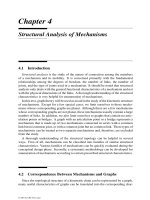
already used for other services. Figure 6.1 shows a diagram of the IMT-2000 spectrum, and
the current use of this spectrum in Europe, the United States, and Japan.
The IMT-2000 spectrum may be partitioned into seven segments. The frequency of each
segment is shown in Table 6.1
Part of Segment 1 is currently used for DECT in Europe, and is also used for PHS, PCS
and DECT in other parts of the world. Segment 2 is used at present for PCS and PHS in the
United States and Japan, respectively. Segments 3 and 6 form 60 MHz frequency division
duplex (FDD) bands. Mobile satellite services (MSS) are in Segments 4 and 7, providing
30 MHz FDD bands. Segment 4 supports the earth-to-space links; while segment 7 provides
the space-to-earth links. The 1980–1990 MHz band in Segment 4 is currently used for PCS
in the United States. Segments 1, 2 and 5 are unpaired and are suitable for time division
duplex (TDD) operation. Segment 5 may be used in the United States for earth-to-space
MSS services.
6.2 Evolution of GSM
The GSM system was initially designed to carry speech, as well as low speed data. Much
has already been discussed regarding speech, so we will concentrate here on data. The user
data rate over the radio interface using a single physical channel, i.e. a single timeslot per
Table 6.1: IMT-2000 spectrum and its segments (MSS stands for mobile satellite services).
Segment Frequency Comment
number band (MHz)
1 1885–1900 Unpaired
2 1900–1920 Unpaired
3 1920–1980 Paired with 6
4 1980–2010 MSS paired with 7
5 2010–2025 Unpaired
6 2110–2170 Paired with 3
7 2170–2200 MSS paired with 4
408
CHAPTER 6. EVOLUTION OF GSM AND CDMAONE TO 3G SYSTEMS
1700 1750 1800 1850 1900 1950 2000 2050 2100 22002150
IMT-2000 IMT-2000
MSS
MSS
ITU
Europe
GSM1800 GSM1800
DECT
PCS
SAT
SAT
USA
PHS
SAT
SAT
Japan
Reserved
Figure 6.1: IMT-2000 spectrum and the current use of this spectrum in Europe, the United States
and Japan. PCS stands for personal communication system, SAT for mobile satellite ser-
vices, DECT for digitally enhanced cordless telecommunications, and PHS for personal
handyphone system.
TDMA frame, was initially 9.6 kb/s. The maximum user data rate available on a single
physical channel has since been increased to 14.4 kb/s by reducing the power of the channel
coding on the full rate traffic channel by means of code symbol puncturing. Apart from
increasing the level of puncturing still further, the other ways to increase the user data rate
beyond 14.4 kb/s are either to allow an MS to access more than an one timeslot per TDMA
frame or to use a higher level modulation scheme (e.g. quadrature amplitude modulation,
QAM) to increase the amount of information that can be transmitted within a single timeslot.
Two new services have been introduced as part of GSM Phase 2+ which allow the user
data rate to be increased by permitting an MS to access more than one timeslot per TDMA
frame. These new services are the high speed circuit switched data (HSCSD) service and
the general packet radio service (GPRS). The HSCSD service allows an MS to be allocated
a number of timeslots per TDMA frame on a circuit-switched basis, i.e. the MS has exclu-
sive use of the allocated resources for the duration of a call [12]. In contrast, GPRS uses
packet-orientated connections on the radio interface (and within the network) whereby a
user is assigned one, or a number of traffic channels only when a transfer of information
is required [13]. The channel is relinquished once the transmission is completed. In the
following sections we will describe these two services in more detail.
6.2. EVOLUTION OF GSM
409
The second approach to increasing the user data rate by employing a higher level modu-
lation scheme is currently being studied under the Enhanced Data Rates for GSM Evolution
(EDGE) project [14]. The basic principle behind EDGE is that the modulation scheme used
on the GSM radio interface should be chosen on the basis of the quality of the radio link. A
higher level modulation scheme is preferred when the link quality is ‘good’, but the system
reverts to a lower level modulation scheme when the link quality becomes ‘poor’. At the
time of writing it appears that EDGE will use the existing Gaussian minimum shift keying
(GMSK) modulation scheme in poor quality channels and eight-level phase shift keying (8-
PSK) in good quality channels. EDGE will also include link adaption functions to allow the
MS and BS to assess the link quality and switch between the different types of modulation
as necessary.
Once developed, the EDGE technology will enhance the range of services offered by
GSM. The initial version of the EDGE technology (Phase 1) will be used to enhance the
GPRS and HSCSD services, leading to enhanced GPRS (EGPRS) and enhanced circuit-
switched data (ECSD). In later releases of EDGE (Phase 2 and beyond) further services
will be introduced which utilise the different modulation schemes [14].
In addition to the developments described above, GSM Phase 2+ contains two other im-
portant enhancements that have a significant impact on the technology from a radio point of
view. In 1993 the European railways, in the form of the Union Internationale des Chemins
de Fer (UIC), chose the GSM technology as the basis of all their future mobile radio com-
munication systems [15]. This led to the introduction of a number of advanced speech call
items (ASCI) which provide the additional functionality required for railways and other
private mobile radio (PMR) environments. The three key elements of ASCI are the voice
broadcast service (VBS), the voice group call service (VGCS) and the enhanced multi-level
precedence and pre-emption (eMLPP) service. The VBS will allow GSM users to broadcast
their voice simultaneously to a number of other users in a chosen talk group. A VBS call
will only occupy a single down-link channel in each cell within which the call is broadcast
and all ‘listening’ MSs will monitor this same channel. VBS calls are simplex in that the
call originator is the only person who can speak during the call. Many applications require
any member of the talk group to become the talker and this functionality is supported in the
VGCS. In this case any member of the talk group may become the ‘talker’ and contention
resolution schemes are included to handle situations where more that one user tries to be-
come the talker simultaneously. These PMR systems also support a facility to ensure that
important calls are successfully completed even at the expense of less important calls. The
eMLPP service allows calls to be prioritised and ensures that the most important calls are
completed, regardless of the network loading.
Another important Phase 2+ item from a radio perspective is the adaptive multi-rate
(AMR) speech coder [16]. The deployment of the GSM half-rate (HR) codec has been
410
CHAPTER 6. EVOLUTION OF GSM AND CDMAONE TO 3G SYSTEMS
somewhat limited because of concerns relating to the speech quality, but the enhanced full-
rate (EFR) codec is more popular amongst GSM operators. The basic concept behind the
AMR technology is that the speech coding rate and the degree of channel coding should
be chosen according to the channel quality. For example, in ‘good’ channels a lower rate
speech coder can be used in an HR traffic channel thereby increasing the system capacity.
However, if the link quality is ‘poor’ FR then a traffic channel will be used and the level of
channel coding increased. At the time of writing the candidate AMR codecs have not yet
been chosen.
6.2.1 High speed circuit-switched data
The HSCSD service [12] is a natural extension of the circuit-switched data services that
were supported in earlier versions of GSM. No changes to the physical layer interfaces be-
tween the different network elements are required for HSCSD. At the higher layers the MS
and the network support the additional functionality required to multiplex and demultiplex
a user’s data onto a number of traffic channels for transmission over both the Abis interface
and the radio interface. Additional functionality is also included at the radio resource man-
agement level to handle the new situation where a number of different traffic channels are
associated with the same connection. For example, when an HSCSD user is handed over
between two cells, there must be a mechanism to ensure that sufficient traffic channels are
available in the new cell before the handover occurs. An HSCSD connection is, however,
limited to a single 64 kb/s circuit on the A interface.
On call set-up the MS provides information to the network which defines the nature of the
HSCSD connection. The multislot class of the MS is used by the network to determine the
maximum number of timeslots that may be accessed by the MS, and the amount of time that
must be allowed between timeslots, e.g. for the purposes of neighbour cell measurements.
This information is used to define the MS’s capabilities for both the HSCSD and GPRS
services. The multislot classes are listed in Table 6.2 along with their associated parameters
[17].
Multislot MSs can be either type 1 or type 2 and this information is shown in the right-
hand column of Table 6.2. Type 2 MSs are required to be able to transmit and receive
simultaneously, whereas type 1 MSs are not. The ‘Rx’ and ‘Tx’ columns give the maxi-
mum number of receive and transmit timeslots that the MS may occupy per TDMA frame,
respectively. The ‘Sum’ column gives the total number of transmit and receive timeslots
the MS may access per TDMA frame. For example, for multislot class 12, ‘Sum’ is 5
which means that the maximum number of transmit and receive slots cannot exceed 5. So
if we have 3 received slots, then we cannot have more than 2 transmit slots in one TDMA
frame. The T
ta
parameter represents the time required for the MS to make a neighbour cell
measurement prior to an up-link transmission. This parameter is not applicable to type 2
6.2. EVOLUTION OF GSM
411
MSs because they are capable of making measurements and transmitting simultaneously.
When the MS is not required to make measurements on neighbouring cells, the T
tb
param-
eter defines the minimum number of timeslots that must be allowed between the end of the
previous down-link timeslot and the next up-link timeslot, or the time between two con-
secutive down-link timeslots that are on different frequencies. In other words, T
tb
is the
amount of time the MS needs to prepare to transmit on the up-link after it has received or
transmitted on a different frequency. The T
ra
parameter is the number of timeslots required
by the MS to make a neighbour cell measurement prior to the reception of a down-link
burst, whereas the T
rb
parameter is the number of timeslots required between the previous
up-link transmission and the next down-link reception, or the time between two consecutive
down-link receptions when the frequency is changed in between receptions. In addition
to its multislot class, the MS provides a range of additional information on call set-up to
allow the network to determine the most appropriate HSCSD configuration. This infor-
mation includes the fixed network user rate, i.e. the data rate that the MS would like to
achieve over the fixed network, the channel coding schemes supported by the MS, and the
maximum number of traffic channels to be used during the connection. This final param-
eter allows the user to control the call cost by limiting the number of traffic channels that
will be occupied. The final multislot configuration is chosen by the network based on the
MS capabilities and the requirements imposed by the services, e.g. whether neighbour cell
measurements are required. The HSCSD service can support both symmetric transmissions,
i.e. the same number of up-link and down-link timeslots, or asymmetric transmissions, i.e.
more timeslots are allocated in one direction. However, in the case of HSCSD connections,
only down-link biased asymmetry is allowed and the up-link timeslot numbers must be a
subset of the down-link timeslot numbers.
6.2.2 The general packet radio service
Many services do not require a continuous bi-directional flow of user data across the radio
interface. To illustrate this, consider the example of a user browsing the Worldwide Web
(WWW) on her lap-top computer using a dial-up connection via a cellular network. Once
a page of information has been downloaded, there will be a pause in the information flow
between the MS and the network as the user reads the information and before more infor-
mation is requested. Using circuit-switched connections for ‘bursty’ services of this nature
represents an inefficient use of the radio resources because a user will continue to occupy a
radio channel for the duration of a call (or browsing session) even though this channel may
only be utilised for a small fraction of the time. Inefficiencies of this type can be overcome
by carrying these services using packet-orientated connections.
The GSM system was initially designed to support only circuit-switched connections at
the radio interface level with user data rates of up to 9.6 kb/s. However, the Phase 2+
412
CHAPTER 6. EVOLUTION OF GSM AND CDMAONE TO 3G SYSTEMS
Table 6.2: The MS multislot classes.
Multislot Maximum number of slots Minimum number of slots Type
class Rx Tx Sum T
ta
T
tb
T
ra
T
rb
111 2 3242 1
221 3 3231 1
322 3 3231 1
431 4 3131 1
522 4 3131 1
632 4 3131 1
733 4 3131 1
841 5 3121 1
932 5 3121 1
10 4 2 5 3 1 2 1 1
11 4 3 5 3 1 2 1 1
12 4 4 5 2 1 2 1 1
13 3 3 NA NA a 3 a 2
14 4 4 NA NA a 3 a 2
15 5 5 NA NA a 3 a 2
16 6 6 NA NA a 2 a 2
17 7 7 NA NA a 1 0 2
18 8 8 NA NA 0 0 0 2
19 6 2 NA 3 b 2 c 1
20 6 3 NA 3 b 2 c 1
21 6 4 NA 3 b 2 c 1
22 6 4 NA 2 b 2 c 1
23 6 6 NA 2 b 2 c 1
24 8 2 NA 3 b 2 c 1
25 8 3 NA 3 b 2 c 1
26 8 4 NA 3 b 2 c 1
27 8 4 NA 2 b 2 c 1
28 8 6 NA 2 b 2 c 1
29 8 8 NA 2 b 2 c 1
NA = Not Applicable
a
=
(
1 if frequency hopping is used
0 if frequency hopping is not used
b
=
(
1 if frequency hopping is used or there is a change from Rx to Tx
0 if frequency hopping is not used and there is no change from Rx to Tx
c
=
(
1 if frequency hopping is used or there is a change from Tx to Rx
0 if frequency hopping is not used and there is no change from Tx to Rx
6.2. EVOLUTION OF GSM
413
specifications now include provision for the support of a packet-orientated service known
as the general packet radio service (GPRS) [13, 18–20]. GPRS attempts to optimise the
network and radio resources, and strict separation between the radio subsystem and the
network subsystem is maintained, although the network subsystem is compatible with the
other GSM radio access procedures. Consequently, the GSM MSC is unaffected. The
allocation of a GPRS radio channel is flexible, ranging from one to eight radio interface
timeslots in a TDMA frame. Up-link and down-link timeslots are allocated separately. The
radio interface resources are able to be shared dynamically between circuit switched and
packet services as a function of service load and operator preference. Bit rates vary from
9 kb/s to more than 150 kb/s per user. GPRS can interwork with IP and X.25 networks.
Point-to-point and multipoint services are also supported, as well as short message services
(SMS).
GPRS is able to accommodate both intermittent, bursty data transfers as well as large
continuous data transmissions. Reservation times are typically from 0.5 s to 1 s. Three
MS modes are supported, each having a different arrangement with circuit switched GSM
services. In this section we provide an overview of the GPRS technology and examine its
impact on the GSM radio interface.
6.2.2.1 The GPRS logical architecture
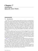
Figure 6.2 is a block diagram showing the architecture of a GSM network that supports
GPRS, and the names that have been given to the interfaces that exist between the different
network components. GPRS services require two additional network components, the gate-
way GPRS support node (GGSN), and the serving GPRS support node (SGSN). As its name
suggests, the GGSN acts as the gateway between external packet data networks (PDN), and
a GSM network that supports GPRS. The GGSN contains sufficient information to route
incoming data packets to the SGSN that is serving a particular MS and it is connected to
external networks via the Gi reference point. (We note that this point of interconnection is
referred to a ‘reference point’ and not an ‘interface’ because no GPRS-specific information
is exchanged at this point.) The SGSN is connected by the Gn interface to GGSNs belong-
ing to its own public land mobile network (PLMN) and it is connected by the Gp interface
to GGSNs belonging to other PLMNs. These two interfaces are very similar, but the Gp
supports additional security functions that are necessary for inter-PLMN communications.
The GGSN may also interface directly with the home location register (HLR) over the Gc
interface, but this is not mandatory.
A SGSN keeps track of the location information and the security information associ-
ated with the MSs that are within its service area. A SGSN communicates with GGSNs
and SGSNs in its own PLMN using the Gn interface and GGSNs in other PLMNs via the
Gp interface. Interfaces also exist between an SGSN and an MSC/VLR (Gs interface),
414
CHAPTER 6. EVOLUTION OF GSM AND CDMAONE TO 3G SYSTEMS
MS BTS BSC
MSC/
VLR
Um Abis
A
SGSN
Gb
GGSN
Gn
HLR
GcGrGs
GGSN
Gp
SGSN
Other GSM networks
D
SMS-GMSC
SMS-IWMSC
Gd
E
C
EIR
Gf
Gn
SM-SC
Gi
PDN
Signalling Interface
Signalling and Data
Transfer Interface
that support GPRS
Figure 6.2: The GPRS network architecture.
an HLR (Gr interface), an EIR (Gf interface) and a short message service gateway MSC
(SMS-GMSC) and interworking MSC (SMS-IWMSC) (Gd interface). The SMS-GMSC
and SMS-IWMSC allow the GSM short message service (SMS) to be carried on the GPRS
channels instead of by the SDCCH and the SACCH. The GPRS support nodes (i.e. the
GGSNs and SGSNs) of a PLMN are interconnected using an Internet protocol (IP) based
backbone network.
6.2.2.2 GPRS transmission plane
This is a layered protocol structure enabling user information transfer and associated con-
trol procedures such as flow control, error detection, error correction and error recovery.
The GPRS transmission plane is shown in Figure 6.3 [18, 19]. We observe in Figures 6.2
and 6.3 the entities MS, BSS (namely BTS connected via the Abis to the BSC), SGSN and
the GGSN; together with the interfaces Um, Gb, Gn and Gi. From the transmission plane
we observe that at the highest level the application is leaving the network via Gi. The GPRS
tunnelling protocol (GTP) tunnels user data and signalling between GPRS support nodes,
SGSN and GGSN, in the backbone network. The transport control protocol (TCP) carries
the GPRS tunnelling protocol (GTP) data units (PDUs) in the GPRS backbone network for
6.2. EVOLUTION OF GSM
415
protocols that need a reliable data link, such as X.25. The user datagram protocol (UDP)
conveys GTP PDUs for protocols, such as Internet protocol (IP) that do not require reliable
links. The TCP provides flow control and protection against lost and corrupted GTP PDUs.
The GPRS backbone network protocol is IP, and is used for routing user data and signalling.
The subnetwork dependent convergence protocol (SNDCP) maps network-level character-
istics onto the lower layer network. The provision of a highly reliable ciphered logical link
is achieved by the logical link control (LLC). The LLC is independent of the radio interface
protocols.
In the BSS the relay function relays LLC PDUs between the radio interface Um and the
Gb interface. In the SGSN the relay function relays packet data protocol (PDP) PDUs
between the Gb and the Gn interfaces. The BSS GPRS protocol (BSSGP) conveys routing
and quality-of-service (QoS) information between a BSS and an SGSN. It does not perform
error control. The network service (NS) layer transports BSSGP PDUs. The radio link
control (RLC) provides a radio dependent reliable link, while the medium access control
(MAC) controls the access signallings, both request and grant, for the radio channel; and
the mapping of the LLC frames onto the GSM physical channel. GSM RF is the GSM
physical layer.
6.2.2.3 High-level functions required for GPRS
Network access control function An access protocol has a set of procedures, such as
registration, authentication and authorisation, admission control, charging and so on, that
allow a user to use the services and facilities the network provides. A user may make an
access attempt, or the user may be paged. The fixed network interface, Gi, may support, at
the discretion of the PLMN operator, multiple access protocols to external networks such
as X.25 and IP.
Anonymous access The idea of anonymous access has also been introduced into GPRS
whereby an MS can access the network without being authenticated and without air-interface
encryption being required. There is also no requirement for the MS to supply its IMSI or
IMEI, although there is provision for the network to request these. One example of an ap-
plication that could make use of this facility is automatic road-tolling, whereby a road user
could use a pre-paid card, inserted into a GSM terminal, automatically to make payment as
she approaches a toll booth.
Packet routing and transfer functions A route consists of an originating network node,
and if required, relay nodes, and finally a destination node. Routing is the transmission
of messages within and between PLMNs. A node forwards data received to the next node
using the relay function. The routing function determines the network GPRS support node
416
CHAPTER 6. EVOLUTION OF GSM AND CDMAONE TO 3G SYSTEMS
Application
IP/X.25
SNDCP
LLC
GSM RF
MAC
RLC
MS
Um
Relay
RLC
MAC
GSM RF
BSSGP
Network
Services
L1 bis
Relay
SNDCP
LCC
BSSGP
Network
Services
L1 bis
Gb
BSS
GTP
UDP/
TCP
IP
L2
L1
SGSN GGSN
IP/X.25
GTP
UDP/
TCP
IP
L2
L1
Gn
Gi
Figure 6.3: GPRS transmission plane [18–20].
(GSN) where the message is sent using the destination address in the message. The routing
function also selects the transmission path to the next GSN along the route. Address transla-
tion is needed to convert one address to another when packets are routed between PLMNs.
Encapsulation is the addition of address and control information to the PDU for routing
within and between PLMNs. Encapsulation, and its reverse, are performed between the
GGSN nodes of PLMNs, and between the SGSN and an MS. The tunnelling function (see
the transmission plane) is the transfer of encapsulated PDUs within and between PLMNs
from where they are encapsulated to where they are decapsulated. There is a compression
function that removes as much overhead information as possible, prior to radio transmis-
sion. The ciphering function provides confidentiality of a user’s data, while the domain
name server function is a standard IP function that resolves any name for GSNs and other
6.2. EVOLUTION OF GSM
417
GPRS nodes within the GPRS backbone networks.
GPRS mobility management and the MS states Mobility management describes the
processes in the mobile radio system that are associated with tracking the movements of
subscribers as they travel around a network. The non-GPRS GSM system uses location
areas and location update procedures to ensure that it always knows the whereabouts of its
MSs. The GPRS uses a similar approach, but instead of using the existing location areas
(LAs) it uses routing areas (RAs). If an MS detects that it has entered a new RA it will
submit a routing area update request message to the network, which if successful, will be
acknowledged with a routing area update accept message. The decision as to whether a
GPRS-equipped MS should perform the RA update procedure as it moves between RAs
will depend on the GPRS state of the MS.
A GPRS-equipped MS may be in any one of three different states for the purposes of
mobility management. In the idle state the MS is ‘not reachable’ as far as the GPRS is
concerned. If an MS is in the idle state, the network does not hold any information regarding
the location of the MS, and hence the MS cannot be paged. It also means that the MS does
not need to perform any RA updates as it moves around the network. MSs in the idle state
cannot access the packet data services without first performing a procedure known as GPRS
attach where the MS announces its identity.
In the standby state the user is attached to the GPRS mobility management (MM). The
MS performs RA and cell selection, and may receive point-to-multipoint multicast (PTM-
M) and point-to-point multipoint group call (PTM-G) data. The SGSN may send data or
signalling information to an MS. The MM state in the MS changes to ready when an MS re-
sponds to a page, as does the state in the SGSN when the response from the MS is received.
The MM state in the MS goes to ready when data or signalling information is sent by the
MS to the network, hence the MM in the SGSN also changes to the ready state. Either the
MS or the SGSN may initiate the GPRS detach procedure to move to the idle state.
In the ready state, the MS informs the network of the selected cell by means of an identifier
included in the BSSGP header of the data packet from the MS. The MS is able to send and
receive PDP PDUs. The network initiates no pages for an MS in the ready state, but pages
for other services may be executed via the SGSN. The ready state is supervised by a timer,
and when the timer expires the MM moves from ready to standby. To move from ready to
idle states, the MS initiates the GPRS detach procedure.
Logical link management functions These are involved with link establishment, main-
tenance and release procedures between an MS and the PLMN over the radio interface.
These functions involve the co-ordination of link state information and the supervision of
data activity over the logical link.
418
CHAPTER 6. EVOLUTION OF GSM AND CDMAONE TO 3G SYSTEMS
Radio resource management functions Allocation and maintenance of radio communi-
cation channels are provided by these functions. The GSM radio resources are dynamically
shared between the circuit mode and GPRS. The GPRS radio resource management is con-
cerned with the allocation and release of timeslots for a GPRS channel; monitoring GPRS
channel utilisation; congestion control; and the distribution of GPRS channel configuration
information that is broadcast on the common control channels.
Network management functions These support operation and management functions for
GPRS.
6.2.2.4Low-level functions
The radio interface functions for GPRS are the medium access control (MAC) and radio
link control (RLC) that operate above the physical layer. The MAC function arbitrates be-
tween MSs attempting to transmit at the same time. It is therefore concerned with collision
avoidance, detection, and recovery following a collision. The MAC function may let a sin-
gle MS use several physical channels simultaneously. The multiplexing of data and control
signalling on both links is affected by the MAC function, as well as by priority scheduling.
The GPRS RLC function supports the transfer of logical link control layer PDUs (LLC-
PDU) between the LLC and MAC entities, the segmentation and reassembly of LLC-PDUs
into RLC data blocks, and backward error correction for the retransmission of uncorrectable
code words.
Packet data logical channels Although circuit switched and GPRS services use the same
physical channels, they have different logical channels. The physical channel dedicated to
packet data is called a packet data channel (PDCH). The logical channels for common con-
trol signalling for packet data are carried by the packet common control channel (PCCCH),
and there is also the packet random access channel (PRACH), an up-link-only channel used
by MSs to initiate data or signalling packet transmission. The other PCCCHs are all down-
link ones. There is the packet paging channel (PPCH) that uses paging groups of MSs
to enable discontinuous reception (DRX) to be used. PPCH can be used for both circuit
switched and packet services. The packet access grant channel (PAGCH) identifies the re-
source assignment to be used by an MS prior to packet transfer, while the packet notification
channel (PNCH) provides notification to a group of MSs that a PTM-M packet transfer is
imminent. The packet broadcast control channel (PBCCH) informs the MSs of packet data
specific information. This information may also be transmitted on the BCCH if a PBCCH
has not been allocated.
The packet data traffic channel (PDTCH) is allocated for data transmissions. It is tem-
porarily allocated to an MS (or a group of MSs in the PTM-M case). An MS may be
6.2. EVOLUTION OF GSM
419
assigned multiple PDTCHs.
There are also packet dedicated control channels. The packet associated control channel
(PACCH) conveys signalling information to a specific MS. The type of information includes
acknowledgements, power control, resource assignment and reassignment. The PACCH and
PDTCH share the resources allocated to an MS. An MS that is transferring a packet can be
paged for circuit switched services on the PACCH. Another dedicated control channel is the
packet timing advance control channel, up-link (PTCCH/U) that conveys in random access
bursts the information to allow the network to deduce the necessary timing advance for the
MS packet transmissions. There is also the packet timing advance control channel, down-
link (PTCCH/D) that transmits timing advance information updates to MSs. One PTCCH/D
is paired with several PTCCH/Us.
A number of PDCHs can share the same physical channel. They are mapped dynamically
onto a 52-multiframe consisting of 12 blocks of four consecutive frames, two idle frames
and two frames for the PTCCH, as shown in Figure 6.4. The 52-multiframe has a duration
of 240 ms, namely two 26-multiframes of the GSM TCH. The first of the 12 blocks in the
52-multiframe is B0 and its PDCH contains PBCCH. On any PDCH with PCCH, up to
12 blocks can be used for PAGCH, PNCH, PDTCH or PACCH on the down-link. On the
up-link PDCH that contains PCCCH, the blocks in the multiframe can carry the PRACH,
PDTCH or PACCH. The mapping of channels onto multiframes is controlled by parameters
broadcast on the PBCCH.
6.2.2.5 The GPRS MS classes
There are three classes of MS as far as the GPRS is concerned and these are based on
the ability of the MS to support the simultaneous use of packet-based and circuit-switched
services. The Class A MSs are able to support the simultaneous transfer of both packet-
based and circuit-switched traffic using different timeslots within the GSM TDMA frame
structure. The Class B MSs can be simultaneously ‘attached’ to both the circuit switched
and packet-based services, e.g. they can receive pages for either service; however, they
cannot transfer packet-based traffic and circuit-switched traffic at the same time. If, for
example, a Class B MS is engaged in a packet-based data transfer and a circuit-switched
connection is established, the transfer of packet data will be suspended for the duration of
Figure 6.4: Multiframe structure for PDCH.
420
CHAPTER 6. EVOLUTION OF GSM AND CDMAONE TO 3G SYSTEMS
the circuit-switched connection. However, in this example there is no requirement for the
GPRS to be deactivated for the particular MS. Class C MSs do not support any simultaneous
use of circuit-switched and packet-based services. A Class C MS can be viewed as operating
in two distinct modes, the GPRS mode and the circuit-switched mode, and it can only be
in one mode at a particular time. For example, if the class C MS is in GPRS mode (i.e. it
is engaged in a packet-based data transfer) and a circuit-switched call arrives at the PLMN
for this particular MS, then the MS will be considered ‘not reachable’ as far as the circuit-
switched call is concerned. It should be noted that the GPRS class of an MS and its multislot
class (see Table 6.2) are separate parameters and there is no direct correlation between the
two.
6.2.2.6 The GPRS quality-of-service
There are four different quality-of-service (QoS) profiles supported in GPRS and these are
dependent on the type of service. For example, an email transaction can tolerate greater de-
lays than, say, an interactive video service, and the QoS profile will be chosen appropriately
in each case. The MS and the network will agree on a particular QoS profile during the
initial service negotiation stages and, as far as possible, the network will attempt to deliver
this QoS to the MS. The QoS service profile is made up of a number of factors, including
the delay class (i.e. the average packet transmission delay), the precedence class (i.e. the
priority value attached to the packets in the event of packet erasure being required as a re-
sult of network congestion), the reliability class (i.e. the probability of errors in the received
data packet), and the peak and average throughput class (i.e. the peak and average rates at
which data are transferred through the network, respectively).
6.2.3 The enhanced data rates for GSM evolution (EDGE)
The driving force behind EDGE is to improve the data rates of GSM by means of enhanc-
ing the modulation methods [14, 21]; specifically, to increase the data rate transmission
per radio timeslot compared with GMSK modulation. Different types of enhanced modu-
lation methods have been considered starting with quaternary offset quadrature amplitude
modulation (Q-O-QAM) and binary offset quadrature amplitude modulation (B-O-QAM),
and ending with 8-level phase shift keying (8-PSK). Although the initial drivers were to
increase the user bit rates and thereby increase the range of services, EDGE has been gilded
as a 3G system and is now a member of the IMT-2000 family. EDGE’s new heady role has
a lot to do with the evolutionary strategy of IS-136, the US TDMA system that is itself an
evolution of the former analogue system, AMPS. The Universe Wireless Communications
(UWC) Consortium advocated a family of mutually compatible TDMA standards known as
UWC-136 that would be developed from the second generation IS-136. The concept was
6.2. EVOLUTION OF GSM
421
that voice services would be provided by the existing IS-136 network and by a new variant
called 136+ which would employ enhanced modulation methods, such as π
=
4 differential
quadrature phase shift keying (π
=
4 DQPSK), coherent QPSK, and coherent 8-PSK offering
a maximum user rate of 43.2 kb/s. Higher rate services would be provided by 136 HS,
which supports user rates up to 521 kb/s for pedestrian mobiles and for vehicular mobiles at
speeds up to 100 km/h. For speeds in the range of 100–500 km/h, rates of 182 kb/s would
be accommodated. In indoor environments, the maximum bit rate would be 4.7 Mb/s. For
136 HS the carrier spacing is 200 kHz (as in GSM) for outdoor/vehicular environments, and
1600 kHz for offices.
The 136 HS (outdoor/vehicular) with its 200 kHz carrier spacing, eight slots per frame,
FDD, with multilevel modulation was part of the UWC-136 IMT EDGE proposal. The
evolution of GSM to EDGE and IS-136 to EDGE is now undertaken jointly by ETSI and
the UWC Consortium. Consequently, EDGE will be compatible with both GSM and IS-
136. The plan [14] is to deploy GPRS, then enhanced GPRS (EDPRS) and enhanced circuit
switch data (ECSD). Then the high level of modulation will be deployed to realise 3G
EDGE services.
EDGE radio interface The radio interface will continue to have GMSK available, but
will be able to use 8-PSK which has three bits per symbol instead of the one-bit type symbol
of GMSK. Since the symbol rate is 271 ksymbols/s then the gross bit rates per slot (includes
overhead) is 22.8 and 69.2 kb/s for GMSK and 8-PSK, respectively. The pulse shape for
8-PSK is such that the 8-PSK spectrum fits within the GMSK spectrum mask. The normal
burst format for EDGE is the same as for GSM, except the two sets of 58 symbols now have
three bits per symbol.
Packet switched transmission The EDGE concept has both packet switched and circuit
switched modes. Indeed, EDGE is more like the grand evolutionary plan of GSM that in-
cludes both GPRS and HSCSD. The enhanced GPRS (EGPRS) differs from GPRS because
with multilevel modulation the channel coding must be improved because it is more vul-
nerable to interference and noise. Accordingly a link adaption scheme regularly estimates
link quality and selects GMSK or 8-PSK and the appropriate channel coding to provide the
highest user bit rate. At the time of writing various schemes are being considered for stan-
dardisation. The coding rate is determined by the amount of puncturing. The rate per time
slot for GMSK is 11.2, 14.5, 16.7 and 22.8 kb/s for code rates of 0.49, 0.64, 0.73, and 1.0,
respectively. For 8-PSK the rate per time slot is 22.8. 34.3, 41.25, 51.6, 57.35 and 69.2 kb/s
for code rates of 0.33, 0.50, 0.60, 0.75, 0.83 and 1.0, respectively.
The enhanced circuit switched (ECSD) mode has the data interleaved over 22 TDMA
frames. For GMSK modulation the rate per time slot is 3.6, 6, 12 and 14.5 kb/s for a code
422
CHAPTER 6. EVOLUTION OF GSM AND CDMAONE TO 3G SYSTEMS
rate of 0.16, 0.26, 0.53 and 0.64, respectively; while for 8-PSK the bit rates have the higher
values of 14.5, 29, 32 and 38.8 kb/s for code rates of 0.42, 0.46, and 0.56, respectively.
For EGPRS when QoS issues are addressed where different factors, such as priority of
packet transmissions, packet delay, packet throughput, maximum and minimum bit rates
that must be handled, and so on, need to be considered, then the maximum bearer rate
should be able to accommodate data rates of 384 kb/s for MS speeds up to 100 km/h and
144 kb/s for an MS travelling at 250 km/h. These rates require a user to make use of multiple
slots per frame if these high bit rates are to be achieved. Fewer slots are required if 8-PSK
is used. Similar comments can be made regarding bearer rates for ECSD. For low bit error
rate transmissions the maximum user bit rate is 57.6 kb/s.
Because of different user requirements there is one class of MSs where 8-PSK is used
in the down-link and only GMSK in the up-link. This provides higher bit rate down-link
transmissions than the up-link ones while at the same time decreasing the complexity of the
MS. Another class of MS will support 8-PSK transmissions on both links.
As with all the 3G standards, we await with interest to see how well they will perform
when they are deployed in operational networks.
6.3 The Universal Mobile Telecommunication System
The universal mobile telecommunication system (UMTS) is, at the time of writing, be-
ing shaped within the Third Generation Partnership Project (3GPP) [22]. The participants
have come together for the specific task of specifying a 3G system based on an evolved
GSM core network and the UTRA FDD and TDD radio interfaces. The 3GPP is composed
of organisational partners, market representation partners and observers. The organisation
partners, i.e. standards organisations, are: ARIB (Japan), CWTS (China), ETSI (Europe),
TI (USA), TTA (Korea) and TTC (Japan). The market representation partners are: Global
Mobile Suppliers Association (GSA), the GSM Association, the UMTS Forum, the Univer-
sal Wireless Communications Consortium (UWCC), and the IPv6 Forum. The observers
are TIA (USA) and TSACC (Canada). The 3GPP activity is overseen by a project coordina-
tion group (PCG). The specifications are developed by four technical specification groups
(TSGs) responsible for the core network, the radio access networks, services and system
aspects, and terminals. Each TSG has a number of working groups. There will be a roll-out
of the specifications; the initial release of the specifications is Phase 1 Release 99. New
capabilities and services will be introduced according to annual specification releases.
The UMTS terminology introduces a number of new terms, and re-names some familiar
ones. Many of these new terms will be defined as they appear in the text, but to assist the
reader give a list of UMTS abbreviations in Table 6.3. We also draw the reader’s attention
to some familiar GSM terms that are different in UMTS. These are presented in Table 6.4
6.3. THE UNIVERSAL MOBILE TELECOMMUNICATION SYSTEM
423
Table 6.3: UMTS abbreviations.
ACLR Adjacent channel leakage power ratio
AI Acquisition indicator
AICH Acquisition indication channel
BCH Broadcast control channel
CCPCH Common control physical channels
CPCH Common packet channel
CPICH Common pilot channel
DPCCH Dedicated physical control channel
DPDCH Dedicated physical data channel
DCH Dedicated channel
FACH Forward access channel
FBI Feedback information
FDD Frequency division duplex
GMSC Gateway MSC
GGSN Gateway GPRS support node
I
uCS
Interface between an RNC and an MSC
I
uPS
Interface between an RNC or BSC and an SGSN
I
ur
Interface between RNCs
MAC Medium access control
MSC Mobile switching centre
MUD Multiuser detection
Node B Base station transceiver
OVSF Orthogonal variable spreading factor
P-CCPCH Primary common physical channel
PCH Paging channel
PCPCH Physical common packet channel
P-CPICH Primary CPICH
PI Paging indicator
PICH Pilot channel
PRACH Physical random access channel
PSC Primary synchronisation code
QPSK Quadrature phase shift keying
RACH Random access channel
RNC Radio network controller (like BSC in GSM)
RNS Radio network subsystem
S-CCPCH Secondary common control physical channel
424
CHAPTER 6. EVOLUTION OF GSM AND CDMAONE TO 3G SYSTEMS
S-CPICH Secondary CPICH
SCH Synchronisation channel
SF Spreading factor
SGSN Serving GPRS (generalised packet rate service)
SSC Secondary synchronisation code
TFCI Transport format combination indicator
TPC Transmit power control
UARFCN UTRA absolute radio frequency channel number
UE User equipment
UMTS Universal mobile telecommunication system
USIM Universal subscriber identity module
UTRA UMTS terrestrial radio interface
The UMTS network architecture block diagram is displayed in Figure 6.5. The core net-
work is encased by a dotted line. The mobile switching centre (MSC) and gateway MSC
(GMSC) are for circuit-switched GSM networks. Because GSM Phase 2+ will also ac-
commodate GPRS, and therefore handle packet data, there is a serving GPRS support node
(SGSN) and a gateway GPRS support node (GGSN). The other core network elements to do
with authentication, home and visitor location registers and equipment identity registers are
essential to support both circuit-switched and packet data networks. Thus, the core network
is architecturally a GSM Phase 2+ core network that is powered up so that it can also handle
the higher volume, higher bit rate, UMTS traffic.
Shown below the core network in Figure 6.5 are two GSM base station subsystems (BSSs)
and two UMTS radio network subsystems (RNSs). The A-interface is between a base sta-
tion controller (BSC) and a mobile switching centre (MSC), and there is an I
uPS
between
a BSC and SGSN, where the subscript uPS signifies a packet switch interface. The A
bis
interface between a BTS and a BSC is also shown.
The UMTS network uses the same core network as GSM, and has interfaces between
the RNC and MSC, SGSN and RNC of I
uCS
,I
uPS
and I
ur
, respectively. The subscript uCS
Table 6.4: GSM and UMTS terminologies of some key entities.
GSM UMTS
Mobile station (MS) User equipment (UE)
Base station transceiver (BTS) Node B
Base station controller (BSC) Radio network controller (RNC)
Base station subsystem (BSS) Radio network subsystem (RNS)
Subscriber identity module (SINM) Universal subscriber identity
module (USIM)
6.3. THE UNIVERSAL MOBILE TELECOMMUNICATION SYSTEM
425
BTS
BSC
BTS Node B
RNC
Node B BTS
BSC
BTSNode B
RNC
Node B
RNS RNSBSS BSS
MSC
VLR
SGSN
GMSC GGSN
AuC
HLR
EIR
AuC = Authentication Center
HLR = Home Location Register
VLR = Visitor Location Register
EIR = Equipment Identity Register
= Traffic and Signalling
MSC = Mobile Switching Centre
SGSN = Serving GPRS Support Node
GGSN = Gateway GPRS Support Node
= Signalling Only
Modified from 3GPP TS 23.002 Version 3.1.0
Core
Network
To external networks To external networks
A
I
ubis
A
bis
I
ur
I
uCS
I
uPS
Figure 6.5: UMTS network architecture.
426
CHAPTER 6. EVOLUTION OF GSM AND CDMAONE TO 3G SYSTEMS
represents circuit-switched. The equivalent of the A
bis
in UMTS is I
ubis
.
This figure is important because it illustrates the evolutionary path from GSM Phase2+ to
UMTS. We see the different radio interfaces of GSM and UMTS plugging into a common
backbone network.
The physical channels in UMTS transfer information across the radio interface. In the
FDD version of UMTS, a physical channel is defined by its code and carrier frequency,
while in TDD it is in terms of its code, carrier frequency and timeslot. The physical layer
(layer 1) of the protocol stack supports transport channels to the medium access control
(MAC) in layer 2. The MAC layer offers logical layers, e.g. radio link control, to the higher
layers. A logical channel is characterised by the type of information transferred, e.g. it may
be handling control information of data traffic.
Figure 6.6 is a block diagram of a UMTS transmitter at the physical layer. Transport
channel data from layer 2 and above are arranged in blocks depending on the type of data.
These blocks are cyclically redundancy coded (CRC) to facilitate error detection at the
receiver. The data are segmented into blocks and channel coding ensues. The coding may
be convolutional or turbo. Sometimes channel coding is not used. Data are then interleaved
to decrease the memory of the radio channel and thereby render the channel more Gaussian-
like. The interleaved data are then segmented into frames compatible with the requirements
of the UTRA interface. Rate matching is performed next. This uses code-puncturing and
data repetition, where appropriate, so that after transport channel multiplexing the data rate
is matched to the channel rate of the dedicated physical channels. A second stage of bit
interleaving is executed, and the data are then mapped to the radio interface frame structure.
Suffice to say at this point is that there are different types of physical channels, namely
pilot channels that provide a demodulation reference for other channels; synchronisation
channels that provide synchronisation to all UEs within a cell; common channels that carry
information to and from any user equipment (UE); and dedicated channels that carry infor-
mation to and from specific UEs.
The physical layer procedures include cell search for the initial synchronisation of a UE
with a nearby cell; cell reselection which involves a UE changing cells while not engaged in
a call; access procedure that allows a UE to initially access a cell; power control to ensure
that a UE and a BS transmit at optimum power levels; and handover, the mechanism that
switches a serving cell to another cell during a call.
6.3.1 The UTRA FDD mode
The UMTS terrestrial radio interface (UTRA) frequency duplex (FDD) mode is the W-
CDMA radio interface of the UMTS, and is designated by the ITU as IMT DS. Referring to
Table 6.1, the UTRA FDD mode uses segment 3 for up-link transmission, and segment 6 for
down-link transmission, i.e. from node B to UE communications. These two segments are
6.3. THE UNIVERSAL MOBILE TELECOMMUNICATION SYSTEM
427
Transport
Channel
Data From
Higher
Layers
CRC
Attachment
Block
Concatenation/
Segmentation
Channel
Coding
1
st
Interleaving
Radio Frame
Segmentation
Rate
Matching
Traffic Channel
Multiplexing
Physical
Channel
Segmentation
2
nd
Interleaving
Physical
Channel
Mapping
To radio interface
Convolutional Coding
Turbo Coding
No Coding
Other
Channels
Figure 6.6: Block diagram of a UMTS transmitter at the physical layer.
called band A. (There is a band B for PCS services in the United States, where 1850–1910
and 1930–1990 MHz are for the up-link and down-link transmission, respectively).
For the UTRA FDD the duplex spacing, i.e. the frequency separation between paired
channels, is in the range 134.8 MHz to 245.2 MHz, and all UE must support a duplex
spacing of 190 MHz. The nominal spacing between radio carriers is 5 MHz, with a chan-
nel raster of 0.2 MHz. This means that the carrier separation may be adjusted in steps of
0.2 MHz, e.g. the carrier spacing may be 4.8 MHz.
The carrier frequency is defined by the UTRA absolute radio frequency channel number
(UARFCN). This number is defined over a frequency band from 0 to 3.7 GHz, and it is the
transmission frequency multiplexed by five. Consequently, the UARFCN, which we denote
as N
u
and N
d
for the up-link and down-link, respectively, will always be an integer because
of the raster frequency of 0.2 MHz. Note that the radio channels in the UTRA FDD are not
necessarily paired as they are in GSM.
Transmitted spectrum The CDMA chip rate is 3.84 Mchips/s, and the transmitted spec-
trum must conform to, i.e. be within, a spectrum mask [23]. As an example, the mask for a
BS with a maximum output power of
43 dBm is shown in Figure 6.7. The abscissa is the
frequency offset,
4
f , from the carrier. The carrier is at
4
f
=
0, not shown in the figure,
and the adjacent carrier would be positioned at
4
f
=
5 MHz. The lightly shaded part of
the figure corresponds to the left-hand ordinate, which is the power measured by a spectral