Tài liệu Enumeration of Kinematic Structures According to Function P2 doc
Bạn đang xem bản rút gọn của tài liệu. Xem và tải ngay bản đầy đủ của tài liệu tại đây (702.32 KB, 26 trang )
Chapter 2
Basic Concepts of Graph Theory
In this chapter we introduce some fundamental concepts of graph theory that are
essential for structure analysis and structure synthesis of mechanisms. Readers are
encouraged to refer to Gibsons [1] and Harary [2] for more detailed descriptions of
the theory.
2.1 Definitions
A graph consists of a set of vertices (points) together with a set of edges or lines.
The set of vertices is connected by the set of edges. Let the graph be denoted by
the symbolG, the vertex by setV , and the edge by setE. We call a graph withv
vertices and e edges a (v, e) graph. Edges and vertices in a graph should be labeled
or colored, otherwise they are indistinguishable.
Each edge of a graph connects two vertices called the end points. We specify an
edge by its end points; that is, e
ij
denotes the edge connecting vertices i and j .An
edge is said to be incident with a vertex, if the vertex is an end point of that edge.
The two end points of an edge are said to be adjacent. Two edges are adjacent if they
are incident to a common vertex. For the (11, 10) graph shown in Figure 2.1a,e
23
is
incident at vertices 2 and 3. Edges e
12
, e
23
, and e
25
are adjacent.
2.1.1 Degree of a Vertex
The degree of a vertex is defined as the number of edges incident with that vertex.
A vertex of zero degree is called an isolated vertex. We call a vertex of degree two
a binary vertex, a vertex of degree three a ternary vertex, and so on. For the graph
shown in Figure 2.1a, the degree of vertex 2 is three, the degree of vertex 10 is one,
and vertex 11 is an isolated vertex.
© 2001 by CRC Press LLC
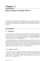
FIGURE 2.1
Graph, subgraph, component, and tree.
2.1.2 Walks and Circuits
A sequence of alternating vertices and edges, beginning and ending with a vertex,
is call a walk. A walk is called a trail if all the edges are distinct and a path if all
the vertices and, therefore the edges are distinct. In a path, no edge may be traversed
more than once. The length of a path is defined as the number of edges between the
beginning and ending vertices. If each vertex appears once, except that the beginning
and ending vertices are the same, the path forms a circuit or cycle. For the graph
shown in Figure 2.1a, the sequence(2,e
23
, 3,e
34
, 4,e
45
, 5) is a path, whereas the
sequence (2,e
23
, 3,e
34
, 4,e
45
, 5,e
52
, 2) is a circuit.
2.1.3 Connected Graphs, Subgraphs, and Components
Two vertices are said to be connected, if there exists a path from one vertex to the
other. Note that two connected vertices are not necessarily adjacent. A graph G is
said to be connected if every vertex in G is connected to every other vertex by at least
one path. The minimum degree of any vertex in a connected graph is equal to one.
© 2001 by CRC Press LLC
For example, the graph shown in Figure 2.1b is connected, whereas the one shown in
Figure 2.1a is not.
A subgraph of G is a graph having all the vertices and edges contained in G.In
other words, a subgraph of G is a graph obtained by removing a number of edges
and/or vertices from G. The removal of a vertex from G implies the removal of all
the edges incident at that vertex, whereas the removal of an edge does not necessarily
imply the removal of its end points although it may result in one or two isolated
vertices.
A graph G may contain several pieces, called components, each being a connected
subgraph of G. By definition, a connected graph has only one component, otherwise it
is disconnected. For example, the graph shown in Figure 2.1a has three components;
the graph shown in Figure 2.1b is a subgraph, but not a component of Figure 2.1a;
whereas the graphs shown in Figures 2.1c and d are components of Figure 2.1a.
2.1.4 Articulation Points, Bridges, and Blocks
An articulation point or cut point of a graph is a vertex whose removal results in an
increase of the number of components. Similarly, a bridge is an edge whose removal
results in an increase of the number of components. A graph is called a block, if it is
connected and has no cut points. The minimal degree of a vertex in a block is equal
to two. For the graph shown in Figure 2.1a, vertices 7 and 9 are cut points, whereas
e
67
,e
78
,e
79
, and e
9,10
are bridges.
2.1.5 Parallel Edges, Slings, and Multigraphs
Two edges are said to be parallel, if the end points of the two edges are identical.
A graph is called a multigraph if it contains parallel edges. A sling or self-loop is
an edge that connects a vertex to itself. Figure 2.2a shows a multigraph, whereas
Figure 2.2b shows a graph with a sling. A graph that contains no slings or parallel
edges is said to be a simple graph. In this text, we shall use the term graph to imply
a simple graph unless it is otherwise stated.
2.1.6 Directed Graph and Rooted Graph
When a direction is assigned to every edge of a graph, the graph is said to be a
directed graph. A rooted graph is a graph in which one of the vertices is uniquely
identified from the others. This unique vertex is called the root. The root is commonly
used to denote the fixed link or base of a mechanism, and it is symbolically represented
by two small concentric circles. Figure 2.3 shows a directed graph in which vertex 1
is identified as the root.
© 2001 by CRC Press LLC
FIGURE 2.2
A multigraph and a graph with a sling.
FIGURE 2.3
A directed graph.
2.1.7 Complete Graph and Bipartite
If every pair of distinct vertices in a graph are connected by one edge, the graph is
called a complete graph. By definition, a complete graph has only one component.
A complete graph of n vertices contains n(n − 1)/2 edges and it is denoted as a K
n
graph. Figure 2.4a shows aK
5
graph.
A graph G is said to be a bipartite if its vertices can be partitioned into two subsets,
V
1
and V
2
, such that every edge of G connects a vertex in V
1
to a vertex in V
2
.
Furthermore, the graph G is said to be a complete bipartite if every vertex of V
1
is
connected to every vertex of V
2
by one edge. A complete bipartite is denoted by K
i,j
,
where i is the number of vertices in V
1
andj the number of vertices inV
2
. Figure 2.4b
shows a K
3,3
complete bipartite.
© 2001 by CRC Press LLC
FIGURE 2.4
K
5
and K
3,3
graphs.
2.1.8 Graph Isomorphisms
Two graphs, G
1
and G
2
, are said to be isomorphic if there exists a one-to-one cor-
respondence between their vertices and edges that preserve the incidence. It follows
that two isomorphic graphs must have the same number of vertices and the same
number of edges, and the degrees of the corresponding vertices must be equal to one
another. Figure 2.5 shows a(6, 9) graph that is isomorphic with theK
3,3
graph shown
in Figure 2.4b.
FIGURE 2.5
A (6, 9) graph.
© 2001 by CRC Press LLC
2.2 Tree
A tree is a connected graph that contains no circuits. Let T be a tree with v vertices.
T possesses the following properties:
1. Any two vertices of T are connected by one and precisely one path.
Proof: Since T is connected, there exists at least one path between any two
vertices, j and k. Assume that two distinct paths, P and Q, exist between
vertices j and k. Following these two paths from vertex j to k, let them first
diverge at vertex j
and then converge at vertex k
. Then, that section of P
from j
to k
and that section of Q from j
to k
form a circuit. This leads to a
contradiction since T contains no circuit. Therefore, there exists one and only
one path between any two vertices of T .
2. T contains (v − 1) edges.
Proof: We prove this property induction. Clearly v = e + 1 holds for a
connected graph of one or two vertices. Assume that v = e + 1 holds for
a tree of fewer than v vertices. If T has v vertices, the removal of any edge
disconnects T in exactly two components because of the first property. By
the induction hypothesis, each component contains one more vertex than edge.
Therefore, the total number of edges in T must be equal to v − 1.
3. Connecting any two nonadjacent vertices of a tree with an edge leads to a graph
with one and only circuit.
Proof: Since every two nonadjacent vertices are connected by a path, walking
from the first vertex to the second along the existing path and returning to the
first vertex by the added edge completes a circuit.
Figure 2.6 shows a family of trees with six vertices.
2.3 Planar Graph
A graph is said to be embedded in a plane when it is drawn on a plane surface such
that all edges are drawn as straight lines and no two edges intersect each other. A
graph is planar if it can be embedded in a plane. Specifically, if G is a planar graph,
there exists an isomorphic graph G
such that G
can be embedded in a plane. G
is
said to be the planar representation ofG. The graph shown in Figure 2.7a is a planar
graph since it can be embedded in a plane as shown in Figure 2.7b. However, the
complete graph and the complete bipartite shown in Figure 2.4 are not planar.
Planar representation of a graph divides the plane into several connected regions,
called loops or circuits. Each loop is bounded by several edges of the graph. The
© 2001 by CRC Press LLC
FIGURE 2.6
A family of trees with six vertices.
FIGURE 2.7
A graph and its planar embedding.
region external to the graph is called the external loop or peripheral loop. For example,
Figure 2.8 shows a planar graph with four loops (including the peripheral loop).
The following theorem can be proved by using a mapping known as the stereo-
graphic projection.
THEOREM 2.1
A graph is embeddable in a plane, if and only if it is embeddable on a sphere.
© 2001 by CRC Press LLC
FIGURE 2.8
A planar graph.
COROLLARY 2.1
The planar embedding of a graph can be transformed into a different planar embed-
ding such that any specified loop becomes the external loop.
Obviously, the nature of planarity of a graph is not affected either by dividing an
edge into two by the insertion of a vertex, or by the reverse process. Two graphs are
said to homeomorphic if one can be made isomorphic to the other by applying this
process. The following theorem, known as Kuratowski’s theorem, can be applied for
identification of planar graphs [3].
THEOREM 2.2
A graph is planar, if and only if it contains no subgraph homeomorphic to the K
5
or
K
3,3
graph.
2.4 Spanning Trees and Fundamental Circuits
A spanning tree, T , is a tree containing all the vertices of a connected graph G.
Clearly, T is a subgraph of G. Corresponding to a spanning tree, the edge set E of G
can be decomposed into two disjoint subsets, called the arcs and chords. The arcs of
G consist of all the elements of E that form the spanning tree T , whereas the chords
consist of all the elements of E that are not in T . The union of the arcs and chords
constitutes the edge set E.
In general, the spanning tree of a connected graph is not unique. The addition
of a chord to a spanning tree forms one and precisely one circuit. A collection
of all the circuits with respect to a spanning tree forms a set of independent loops
or fundamental circuits. The fundamental circuits constitute a basis for the circuit
© 2001 by CRC Press LLC
space. Any arbitrary circuit of the graph can be expressed as a linear combination of
the fundamental circuits using the operation of modulo 2, i.e., 1 + 1 = 0.
Figure 2.9a shows a (5, 7) graphG, Figure 2.9b shows a spanning treeT , and
Figure 2.9c shows a set of fundamental circuits with respect to the spanning treeT .
The arcs of G consist of edges e
15
,e
25
,e
34
, and e
35
. The chords of G consist of
e
12
,e
23
, ande
14
. Figure 2.9d shows a circuit obtained by a linear combination of two
fundamental circuits.
FIGURE 2.9
A spanning tree and the corresponding fundamental circuits.
© 2001 by CRC Press LLC
2.5 Euler’s Equation
Let L denote the number of independent loops of a planar connected graph and
˜
L
represent the total number of loops. Then
˜
L = L + 1 . (2.1)
Euler’s equation, which relates to the number of vertices, the number of edges, and
the number of loops of a planar connected graph can be written as
˜
L = e − v + 2 . (2.2)
In terms of the number of independent loops, we have
L = e − v + 1 . (2.3)
2.6 Topological Characteristics of Planar Graphs
In this section, we explore some fundamental properties of planar connected graphs
that are essential for structure analysis and structure synthesis of mechanisms.
Let d
i
denote the degree of a vertex i, and e denote the number of edges in a graph
G. Since each edge is incident with two end vertices, it contributes 2 to the sum of
the degrees of the vertices. Therefore, the sum of the degrees of all vertices in a graph
is equal to twice the number of edges:
i
d
i
= 2e. (2.4)
For the (8, 10) graph shown in Figure 2.8, we haved
1
= d
2
= d
3
= d
4
= 3, and
d
5
= d
6
= d
7
= d
8
= 2. Therefore,
8
i=1
d
i
= 4 × 3 + 4 × 2 = 2 × 10 .
Let the vertices be partitioned into two groups: one consists of even-degree vertices
and the other odd-degree vertices. Then, Equation (2.4) can be rearranged as
i
d
i
(even-degree vertices) +
i
d
i
(odd-degree vertices) = 2e. (2.5)
© 2001 by CRC Press LLC