Tài liệu GSM, cdmaOne and 3G systems P2 doc
Bạn đang xem bản rút gọn của tài liệu. Xem và tải ngay bản đầy đủ của tài liệu tại đây (1.26 MB, 86 trang )
Chapter
2
The GSM System
2.1 Introduction
In 1982, the main governing body of the European telecommunication operators, known
as CEPT (Conf´erence Europ´eene des Postes et T´el´ecommunications), created the Groupe
Sp´ecial Mobile (GSM) committee and tasked it with specifying a pan-European cellular
radio system to operate in the 900 MHz band. The system was conceived to overcome
the perceived capacity limitations of the successful analogue systems already deployed in
several European countries (e.g. the Nordic Mobile Telephone system, NMT, in the Nordic
countries). The pan-European cellular standard would support international roaming and
provide a boost for the European telecommunications industry. The power centres behind
the proposed system were the 12 countries of the European Economic Community (EEC),
the 26 countries involved in CEPT and the French and German PTTs. There was also strong
support from the Nordic countries and the UK Government and industry. The French and
German alliance, formed in 1983, was joined by Italy in 1985, and in 1986 the UK joined
to form the Quadripartite [1].
After initial discussions, three working parties (WPs) were created to deal with specific
aspects of the system definition, and later on a fourth WP was added. In 1986, a permanent
nucleus was set up in Paris to co-ordinate the efforts of the working parties and also manage
the generation of the system recommendations. The WPs were required to define the system
interfaces that would allow a mobile, in the form of either a hand-held or vehicular mounted
unit, to roam throughout the countries where the new system had been deployed and have
access to the full range of services. Compared with the existing analogue systems, the
new system was required to have a higher capacity, comparable or lower operating costs
and a comparable or better speech quality. The system was also required to co-exist with
the analogue systems. A common pan-European bandwidth allocation for the new system
65
GSM, cdmaOne and 3G Systems. Raymond Steele, Chin-Chun Lee and Peter Gould
Copyright © 2001 John Wiley & Sons Ltd
Print ISBN 0-471-49185-3 Electronic ISBN 0-470-84167-2
66
CHAPTER 2. THE GSM SYSTEM
of 890–915 MHz and 935–960 MHz was agreed; however, by the time the system was to
be deployed, parts of this band would be occupied by analogue cellular systems in some
countries (e.g. the Total Access Communications System, TACS, in the United Kingdom).
In these countries only a portion of the band would be used initially for GSM.
Although studies in various European countries had concluded that digital systems were
to be preferred over analogue systems, the choice of the multiple access scheme was not
as clear-cut. It was decided that a number of different system proposals, put forward by
companies and consortia from a number of different European countries, should be evalu-
ated in prototype form. There were eight different system proposals. The MATS-D system
proposed by TEKADE incorporated three different multiple access schemes, namely code
division multiple access (CDMA), frequency division multiple access (FDMA) and time
division multiple access (TDMA). The CD900 system proposed by SEL was a wideband
TDMA system in conjunction with spectral spreading [2, 3]. The remaining six proposals
were all based on narrow-band TDMA. The SFH900 system proposed by LCT used fre-
quency hopping in combination with Gaussian minimum shift keying (GMSK) modulation,
Viterbi equalisation and Reed–Solomon channel coding. Bosch proposed the S900-D sys-
tem, which used four-level frequency shift keying (FSK) modulation, and Ericsson proposed
the DMS90 system which used frequency hopping, GMSK modulation and an adaptive de-
cision feedback equaliser (DFE). The Mobira system and the MAX II system proposed by
Televerket were similar to the DMS90 system. Finally, the system proposed by ELAB of
Norway employed adaptive digital phase modulation (ADPM) and a Viterbi equaliser to
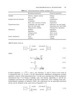
combat the effects of intersymbol interference (ISI). Some of the basic features of the eight
different systems are given in Table 2.1 [4].
The different systems were trialled in Paris at the end of 1986 and the most spectrally effi-
cient (and ‘unofficial winner’) was the system proposed by ELAB. During 1987 the results
of the trial were discussed and eventually agreement was reached on the main characteris-
tics of the new system. The wideband solutions advocated by the French and Germans were
not adopted for a number of reasons, including the probability that the 1 µm VLSI technol-
ogy, needed to support the complex baseband signal processing required by these systems,
might not be available within the proposed time-scales. By June 1987 there was complete
agreement that the system should employ narrow-band TDMA and that it would have many
of the features of the ELAB system. The system would initially support eight channels per
carrier with eventual evolution to 16 channels per carrier.
The speech codec was chosen based on a subjective comparison of six different codecs at
16 kb/s. The two codecs which performed significantly better than the others were a residual
excited linear prediction (RELP) codec and a multipulse excitation linear prediction codec
(MPE-LPC). These two designs were merged to produce a regular pulse excitation LPC
(RPE-LPC) with a net bit rate of 13 kb/s.
2.1. INTRODUCTION
67
Tabl e 2 .1: Some basic features of the GSM prototype systems.
Multiple Transmission Carrier Modulation Channels
access bit rate spacing scheme per
method (kb/s) (kHz) carrier
CD-900 CDMA/TDMA 7980 4500 4-PSK 63
MATS-D CDMA/TDMA 2496 1250 QAM 32
FDMA 19.5 25 GTFM 1
ELAB TDMA 512 600 ADPM 12
DMS90 TDMA 340 300 GMSK 10
MOBIRA TDMA 252 250 GMSK 9
SFH-900 TDMA 200 150 GMSK 3
S900-D TDMA 128 250 4-FSK 10
MAX II TDMA 104.7 50 8-PSK 4
The success of the ELAB system in the Paris trials focused attention on the Viterbi
equaliser, which out-performed the DFE used in other systems. Although Reed–Solomon
channel coding was heavily favoured amongst the prototype systems, the high levels of syn-
ergism between the Viterbi equaliser and the convolutional decoder, which also employs the
Viterbi algorithm, meant that convolutional channel coding was chosen for the new system.
The adaptive digital phase modulation (ADPM) scheme employed by the ELAB system
was initially chosen as the main candidate for the new system. However, GMSK was later
preferred because of its improved spectral efficiency.
The initial drafts of the GSM specifications became available around the middle of 1988
and by the end of that year the GSM working parties and the associated expert groups
had completed a substantial part of the specifications of the pan-European system. Around
this time it became clear that it would not be possible to fully specify every feature of the
proposed system in time for the launch in 1991. For this reason, the system specification was
divided into two phases. The most common services (e.g. call forwarding and call barring)
were included in the Phase 1 specifications which were frozen in 1990. The remaining
services (e.g. supplementary services and facsimile) were delayed until the Phase 2 release.
The second phase was also used to rectify faults in, and improve the performance of, the
Phase 1 system.
At the request of the United Kingdom, a version of GSM, operating in the 1800 MHz
band, was included in the specification process, tailored to the requirements of the emerg-
ing Personal Communications Networks (PCN). This system became known as the Digital
Cellular System at 1800 MHz (DCS1800). From this point onwards we shall use the term
GSM900 to describe the system operating in the 900 MHz band to distinguish it from the
1800 MHz system. The term GSM will be used to refer to both systems. It is important to
68
CHAPTER 2. THE GSM SYSTEM
note that the term GSM1800 is also commonly used to refer to the DCS1800 system. The
DCS1800 system adaptation began in 1990 and, in 1991, Phase 1 of the DCS1800 system
specifications were frozen and were subsequently released as a set of amendments to the
GSM900 Phase 1 specifications. The amendments were termed delta recommendations or
∆-recs. In Phase 2 of the specifications, which were frozen in June 1993, the GSM900
system and the DCS1800 system were combined into the same set of documents.
During the development of the Phase 2 specifications it became clear that the task of
revising the specifications for a third time would be huge. For this reason it was decided
that beyond Phase 2 the GSM system should gradually evolve as new features arrive and this
continual evolution has become known as Phase 2+. Some of the more significant features
proposed for Phase 2+ included the half-rate speech coder, an increase in the maximum
mobile speed for reliable communications and a higher power 4 W mobile for the DCS1800
system.
In 1988, GSM became a Technical Committee of the newly created European Telecom-
munications Standards Institute (ETSI). Each of the four working parties became Sub-
Technical Committees (STCs). At the end of 1991 the scope of the GSM Technical Com-
mittee was widened to include the specification of a successor to GSM and, for this reason,
the technical committee was renamed the Special Mobile Group (SMG) with the STCs be-
coming SMG1 to 4. SMG5 was added with the task of specifying the Universal Mobile
Telecommunication System (UMTS), GSM’s successor [5]. Several other STCs have been
added and their responsibilities are summarised in Table 2.2. The term GSM is still used to
describe the system, but it has been renamed ‘The Global System for Mobile Communica-
tions’. SMG5 has since been discontinued and the task of developing the specifications for
UMTS has been distributed among the other committees.
In this chapter we give an overview of GSM. We have concentrated our description on the
GSM radio interface, since this has a direct impact on the capacity of a cellular system. The
reader wishing to learn more about GSM is either referred to books that are solely dedicated
to describing the system [6, 7], or the complete GSM specifications themselves which run
to some 5000 pages and describe all the complexities of GSM.
2.2 An Overview of the GSM Network Architecture
In this section we briefly examine the different components that together make up a GSM
network. Many of these components are common to any cellular network; however, a few
are peculiar to GSM. We also note that GSM sometimes uses its own terminology to de-
scribe familiar components. A block diagram showing the simplified hierarchical structure
of the GSM public land mobile network (PLMN) is given in Figure 2.1.
2.2. AN OVERVIEW OF THE GSM NETWORK ARCHITECTURE
69
Tabl e 2 .2: Responsibilities of SMG committees within ETSI.
SMG Responsibilities
1 Definition of the services and facilities
of the systems within the scope of SMG
(i.e. GSM900, DCS1800, UMTS)
2 Specification of the physical layer
of the radio interface of GSM900,
DCS1800 and UMTS
3 Specification of the network aspects
of GSM900, DCS1800 and UMTS
4 Specification of the data and telematics
services for GSM900, DCS1800 and UMTS
5 Co-ordination of the specification of
UMTS (discontinued)
6 Specification of the network management
functions of GSM900, DCS1800 and UMTS
7 Specification of the mobile station
conformity requirements for GSM900 and
DCS1800
8 Development of base station system
testing procedures for GSM900, DCS1800
and UMTS
9 Specification of the subscriber
identity module and mobile equipment
interface for GSM900, DCS1800 and UMTS
10 Specification of the security aspects
of GSM900, DCS1800 and UMTS
11 Specification of the speech coding
aspects of GSM900, DCS1800 and UMTS
12 Specification of the system architecture
aspects of GSM900, DCS1800 and UMTS
2.2.1 The mobile station
A subscriber will use a mobile station (MS) to make and receive calls via the GSM network.
The MS is composed of two distinct functional entities, the subscriber identity module
(SIM), which is a removable smart card containing information that is specific to a particular
subscriber, and the mobile equipment (ME), which is essentially the mobile phone itself
without the SIM.
The ME may be sub-divided into three functional blocks. The first is the terminal equip-
ment (TE) and this performs functions that are specific to a particular service, for example
a fax machine. The TE does not handle any functions that are specific to the GSM system.
The second functional block is the mobile termination (MT) and this carries out all the func-
70
CHAPTER 2. THE GSM SYSTEM
GATEWAY
MSC
OMC
ADC
NMC
AUC
VLR
HLR
MSC
EIR
MSC & SUPPORT
BSS
BSS
MS
MS
MS
MS
MS
MTTE
A
A
A
BTS
A-bis
BSC
BTS
A-bis
BTS
A-bis
BSS
U
m
U
m
Other networks
Figure 2.1: GSM network architecture.
tions relating to the transmission of information over the GSM radio interface. Finally, the
third functional block is the terminal adapter (TA), which is used to ensure compatibility
between the MT and the TA. For example, a TA would be required to interface between an
ISDN-compatible MT and a TA with a modem interface.
The SIM is a ‘credit-card’ size (or smaller, in the case of some handheld units) smart card
which can be used by a subscriber to ‘personalise’ an ME. We emphasize that, in GSM
terminology, the term MS refers to the combination of a SIM and an ME. The SIM has an
area of non-volatile memory which is used to store information specific to a particular sub-
scriber [8] and this includes the subscriber’s unique international mobile subscriber identity
(IMSI) number. This number is used to identify each individual subscriber within the GSM
network and it consists of not more than 15 decimal digits. The first three digits of the IMSI
form the mobile country code (MCC) and this is used to identify the country of the partic-
ular subscriber’s home network, i.e. the network with which the subscriber is registered.
The subscriber will always be billed through her home network, even when she incurs call
charges on other networks.
The next two digits of the IMSI form the mobile network code (MNC) and this identifies
2.2. AN OVERVIEW OF THE GSM NETWORK ARCHITECTURE
71
the subscriber’s home PLMN within the country indicated by the MCC. The MNCs are
allocated by a relevant authority within each country. The remaining digits of the IMSI
are the mobile subscriber identification number (MSIN) which is used to uniquely identify
each subscriber within the context of their home PLMN. From this discussion it is clear that
the IMSI is unique to each individual subscriber and it may also be used to determine the
subscriber’s home network.
The SIM will also contain the subscriber’s secret authentication key, K
i
, the authentication
algorithm, A3, and the cipher key generation algorithm, A8. The functions of each of these
items will be examined in detail in Section 2.5, suffice to say at this point that they are
used to implement the security features of GSM and they are stored in the SIM under heavy
protection. The language preference indicator is also located in the SIM and this is used to
indicate the language to be used on the MS screen.
The items described above are mandatory and must be present in any SIM that conforms
to the GSM specifications. The SIM may also contain a number of optional items which
will include the subscriber’s abbreviated dialling numbers. This is a list of the subscriber’s
commonly used telephone numbers that may be accessed using short numeric codes or using
a system of menus. The SIM may also contain a list of the last number(s) that the subscriber
has dialled and an area of storage for the subscriber’s short messages. GSM provides the
facility for a subscriber to send and receive short alpha-numeric text messages from their
MS and this facility has been termed the short message service (SMS).
Inserting an SIM card into an ME effectively personalises the equipment to the partic-
ular subscriber. Any incoming calls for the subscriber will be routed to the ME and any
charges incurred using the ME will be billed to the subscriber’s account. This feature al-
lows subscribers easily to switch between different MEs when, for example, their ME has
been returned for repair and a different ME must be used temporarily.
One of the major motives behind the development of the GSM system was to allow sub-
scribers the freedom to roam throughout Europe whilst maintaining the ability to make and
receive calls using the same MS. This is only possible where compatible networks exist
in each country and it is not possible to roam between GSM900 and DCS1800 networks
using the same MS, unless the MS has a dual-mode capability allowing it to operate with
the 900 MHz and 1800 MHz systems. However, the SIM card has also introduced the
concept of ‘SIM roaming’ whereby a subscriber may roam between different, incompatible
networks by renting an appropriate ME and personalising it with her SIM card. This facility
has become particularly attractive with the introduction in the United States of the PCS1900
system (or GSM1900 as it is commonly called), which is a derivative of the GSM system
operating in the US 1900 MHz PCS band. Although GSM900 and DCS1800 equipment
will be incompatible with the PCS1900 system, a GSM900 subscriber from Europe could
rent a PCS1900 ME whilst visiting the United States and, by inserting her SIM card into the
72
CHAPTER 2. THE GSM SYSTEM
rented equipment, would be able to receive calls via her normal telephone number and have
the resulting charges billed to her home account. The ability to perform normal roaming or
SIM card roaming will be subject to the existence of an appropriate roaming agreement be-
tween the subscriber’s home network operator and a network operator in the country where
the subscriber would like to roam.
In first generation analogue cellular systems, a user’s unique electronic serial number
(ESN) is programmed directly into the subscriber unit (i.e. the mobile phone). In the
event that a subscriber decides to switch to a different network, the mobile phone must
be exchanged or reprogrammed. The introduction of the SIM card allows the subscriber
complete freedom to switch between different networks without the need to exchange or
reprogramme the ME itself. For example, if a GSM900 subscriber wishes to switch from
Network 1 to Network 2, the old SIM card can be replaced with a new one obtained from
the operator of Network 2 and the same GSM900 mobile phone may be used on the new
network.
The situation is slightly more complicated in some countries (e.g. the United Kingdom)
where the handsets are subsidised by the network operator and this subsidy must be re-
turned if a subscriber decides to change networks. In this case a locking mechanism will be
included such that a handset cannot be used with an SIM from a different network operator
until an unlocking code has been entered. The subscriber must make a payment to the ex-
isting network operator to receive this unlocking code and this represents the repayment of
the handset subsidy. The interface between the SIM and the ME is fully defined in the spec-
ifications and is referred to as the SIM–ME interface. This ensures compatibility between
the SIMs and MEs of different manufacturers.
2.2.2 The base station subsystem
An MS communicates with a base transceiver station (BTS) via the radio interface, U
m
.
A BTS performs all the transmission and reception functions relating to the GSM radio
interface along with a degree of signal processing. In some ways a BTS can be considered
to be a complex radio modem that takes the up-link radio signal from an MS and converts
it into data for transmission to other machines within the GSM network, and accepts data
from the GSM network and converts it into a radio signal that can be transmitted to the MS.
The BTSs are used to form the coverage cells in GSM and it is their position that determines
the network’s coverage and capacity.
Although a BTS is concerned with transmission and reception over the radio interface, it
plays only a minor role in the way the radio resources are allocated to the different MSs.
Instead, the management of the radio interface is performed by a base station controller
(BSC). The management functions include the allocation of radio channels to MSs on call
set-up, determining when a handover is required and identifying a suitable target BTS and
2.2. AN OVERVIEW OF THE GSM NETWORK ARCHITECTURE
73
controlling the transmitted power of an MS to ensure that it is just sufficient to reach its
serving BTS. BSCs vary from manufacturer to manufacturer, but a BSC might typically
control up to 40 BTSs. In addition to its processing capacity, a BSC will also have a limited
switching capability, enabling it to route calls between the different BTSs under its control.
The interface between a BSC and an associated BTS is known as the A-bis interface and it
is fully defined by an open, or public, specification. In theory this allows a network operator
the freedom to procure their BSCs and BTSs from different equipment manufacturers. The
BTS and BSC are collectively known as the base station subsystem (BSS).
2.2.3 The mobile services switching centre
Referring to Figure 2.1, we see that each BSS is connected to a mobile services switching
centre (MSC). The MSC is concerned with the routing of calls to and from the mobile
users. It possesses a large switching capability that varies between manufacturers, but a
typical MSC will control a few tens of BSCs and it will have a capacity of several tens of
thousands of subscribers. The MSC is similar to the switching exchange in a fixed network.
However, it must include additional functions to cope with the mobility of the subscribers,
e.g. functions to cope with location registration and handover. The GSM specifications use
the term MSC area to describe the part of a network that is covered by a particular MSC
and its associated BSCs and BTSs. The interface between the MSC and BSS is known
as the A interface and it is fully defined in the specifications, giving the network operator
the freedom to choose their MSCs and BSCs from different manufacturers. The interface
between different MSCs is called the E interface.
The network operator may also select one or a number of MSCs to act as gateway MSCs
(GMSC). As its name would suggest, the GMSC provides the interface between the PLMN
and external networks. In the event of an incoming call from another network, the GMSC
communicates with the relevant network databases to ensure that the call is routed to the
appropriate MS.
2.2.4The GSM network databases
In the previous sections we have examined the various components within the GSM network
that are used to form the communication path between an MS and another MS or a user on
another network, e.g. the public switched telephone network (PSTN). Equally important in a
commercial network are the means of charging and billing subscribers, maintaining accurate
subscription records and preventing fraudulent network access. In a cellular network where
subscribers are free to roam throughout the coverage area, the network must also possess
some way to track MSs so that it is able successfully to route incoming calls to them. All
of these functions are supported using a combination of databases or registers.
74
CHAPTER 2. THE GSM SYSTEM
The home location register (HLR) is used to store information that is specific to each sub-
scriber. It will contain details of a particular user’s subscription, e.g. the services to which
they have access, and some information relating to the location of each subscriber, e.g. the
details of the MSC area within which the subscriber is currently registered. The information
contained within the HLR may be accessed using either the subscriber’s IMSI or mobile sta-
tion international ISDN (MSISDN) number, which is essentially the subscriber’s telephone
number. Every GSM subscriber will have an entry in the HLR of their home network. The
interface between an HLR and an MSC is called the C interface.
Another GSM database that is very closely associated with the HLR is the authentication
centre (AuC). The AuC is solely used to store information that is concerned with GSM’s
security features, i.e. user authentication and radio path encryption. It will contain the
subscriber’s secret K
i
key and the A3andA8 security algorithms. The functions of the K
i
key and the security algorithms are described in detail in Section 2.5. The AuC will only
ever communicate with the HLR and it does this using the H interface.
Another important database used in the GSM system is the visitor location register (VLR).
A VLR is associated with one or a number of MSCs and it contains information relating
to those subscribers that are currently registered within the MSC area(s) of its associated
MSC(s). The area that is served by a particular VLR is termed the VLR area.Itistermedthe
visitor location register because it holds information on those subscribers that are visiting
its VLR area. The main function of the VLR is to provide a local copy of the subscriber’s
information for the purposes of call handling and it removes the need to continually access
the HLR to retrieve information about a particular subscriber. This becomes important
in a system such as GSM where subscribers may use networks in countries other than the
country of their home network. The VLR also contains information that enables the network
to ‘find’ a particular subscriber in the event of an incoming call.
The process of locating a subscriber is facilitated by subdividing the network’s coverage
area into a number of location areas, each consisting of one or a number of cells or sectors.
The VLR will contain the details of the location area in which each subscriber is registered.
In the event of an incoming call, an MS will be paged in each of the cells within its loca-
tion area and this means that the MS may move freely between the cells of a location area
without having to inform the network. However, when an MS moves between cells belong-
ing to different location areas, it must register in the new area using the location updating
procedure. Where a subscriber moves between location areas controlled by different VLRs,
its details are copied from the HLR to the new VLR. The HLR will also ensure that the
subscriber’s details are removed from the old VLR. The interface between the HLR and the
VLR is called the D interface and the interface between an MSC and its associated VLR is
called the B interface. An interface also exists between different VLRs and this is termed
the G interface.
2.2. AN OVERVIEW OF THE GSM NETWORK ARCHITECTURE
75
The introduction of the SIM card in GSM means that tracking a subscriber no longer im-
plies the tracking of a piece of equipment, and vice versa. For this reason the equipment
identity register (EIR) has been introduced to allow the network operator to track stolen and
malfunctioning MEs. Each ME is assigned a unique 15-digit international mobile equip-
ment identity (IMEI) at the point of manufacture. Each model of ME must undergo a
process known as type approval, wherein a number of its features are tested using a GSM
system simulator. The type approval testing is carried out by accredited laboratories that
are independent of any manufacturing or operating companies and it is used to ensure that
all GSM ME models meet a minimum standard, regardless of the manufacturer. Once an
ME model has been type approved it will be assigned a six-digit type approval code (TAC)
and this forms the first six digits of an ME’s IMEI. The next two digits of the IMEI rep-
resent the final assembly code (FAC) and this is assigned by the manufacturer to identify
the place where the ME was finally assembled or manufactured. The next six digits of the
IMEI represent the ME’s serial number (SNR) and this will be unique to every MS for a
given combination of TAC and FAC. The remaining digit of the 15-digit IMEI is defined as
‘spare’.
The EIR is used to store three different lists of IMEIs. The white list contains the series of
IMEIs that have been allocated to MEs that may be used on the GSM network. The black
list contains the IMEIs of all MEs that must be barred from using the GSM network. This
will contain the IMEIs of stolen and malfunctioning MEs. Finally, the network operator
may also use a grey list to hold the IMEIs of MEs that must be tracked by the network for
evaluation purposes.
During an access attempt or during a call, the network has the ability to command an MS
to supply its IMEI at any time. If the IMEI is on the black list or it is not on the white list, the
network will terminate the call or access attempt and the subscriber will be sent an ‘illegal
ME’ message. Once an MS has failed an IMEI check it will be prevented from making any
further access attempts, location updates or paging call responses. However, this MS may
still be used to make emergency calls. The IMEI check is performed within the EIR and the
IMEI is passed to the EIR by the MSC that is currently serving the MS. The results of the
IMEI check are then returned by the EIR to the relevant MSC. The interface between the
EIR and the MSC is termed the F interface.
2.2.5 The management of GSM networks
From an operator’s viewpoint, an effective network management system is an important part
of any telecommunications network. It is essential for the network operator to be able to
identify problems in the network at an early stage and correct them quickly and efficiently.
It is also important for the network operator to be able to make changes to the network
configuration with a minimum of effort and without affecting the service provided to its
76
CHAPTER 2. THE GSM SYSTEM
subscribers. The functional blocks associated with the management of the GSM network,
as shown in Figure 2.1, are the operations and maintenance centre (OMC), the network
management centre (NMC) and the administration centre (ADC).
The OMC provides the means by which the operator controls the network. Each OMC
will typically be in charge of a subsystem, e.g. the BSS or the Network Switching Subsys-
tem, NSS (i.e. the MSC, HLR, VLR, etc.) The NMC is concerned with the management of
the entire network and it generally has a wider operational role than an OMC. The ADC is
concerned, as its name would suggest, with the administrative functions required within the
network.
2.3 The GSM Radio Interface
The radio interface provides the means by which an MS communicates with the BTSs of a
GSM network whilst it moves within the coverage area. The performance of the radio inter-
face, and particularly its ability to provide acceptable speech links in the face of co-channel
interference from other users within the system, acutely affects the overall capacity of a cel-
lular system. In this section we examine the features of the GSM radio interface. Figure 2.2
shows a simplified block diagram of the GSM radio link. In the following sections we will
examine the function and operation of each of these blocks in some detail. It is difficult to
keep to a strict top-down or bottom-up description of the GSM radio interface because, in
some cases, in order to appreciate the reason for a particular feature of the radio interface,
it is necessary to understand some features associated with a higher or lower layer protocol.
For this reason we have adopted a somewhat unconventional approach to the description
of the radio interface. We will begin by examining the modulation scheme and the carrier
frequencies used in GSM. Then we will discuss the construction of the TDMA bursts, or
packets, and the way in which these may be demodulated in the presence of intersymbol
interference (ISI) caused by the radio channel and the modulation process itself. Follow-
ing this we will discuss the different channels that are available in GSM and the manner in
which the radio resources are allocated to each of the channels. At this point we will have
effectively built up a picture of the radio interface as a ‘bit pipe’ where data are applied to
the transmitter and the same data, possibly with a number of errors, are recovered at the
receiver.
We will then turn our attention to the coding, interleaving and ciphering processes that
occur on the GSM radio interface. These processes are different for speech information,
user data (e.g. fax transmissions) and signalling information and, therefore, we will deal
with each of these different types of information separately. Finally, we will bring the two
halves of our radio interface description together by describing the manner in which the
coded, interleaved and ciphered, or encrypted, data are mapped onto the TDMA bursts.
2.3. THE GSM RADIO INTERFACE
77
Figure 2.2: Block diagram of a GSM transmitter and receiver.
2.3.1 The GSM modulation scheme
The modulation scheme used in GSM is Gaussian minimum shift keying (GMSK) with
a normalised bandwidth product, BT, of 0.3 and the modulation symbol rate is around
271 kb/s. For the reader not familiar with GMSK modulation we will include a brief de-
scription of its fundamentals. GMSK is based on a simpler modulation scheme known as
minimum shift keying (MSK) in which the carrier amplitude remains constant and the in-
formation is carried in the form of phase variations. A logical ‘1’ will cause the carrier
phase to increase by 90
over a bit period and a logical ‘0’ will cause the carrier phase to
decrease by the same amount. This phase change is produced by instantaneously switching
the carrier frequency between two different values, f
1
and f
2
, according to the input data
and, therefore, MSK is a special case of FSK modulation. The frequencies f
1
and f
2
are
given by
f
1
=
f
c
+
R
b
=
4
f
2
=
f
c
R
b
=
4
(2.1)
where R
b
is the modulation symbol rate (
271 kb/s in GSM) and f
c
is the nominal car-
rier frequency. It is interesting to note that, in MSK, the carrier frequency, f
c
,isnever
transmitted.
This shows that MSK requires instanteous changes in the carrier frequency and, conse-
quently, the modulated spectrum is, in theory, infinitely wide. The spectrum of an MSK
modulated signal may be compressed by filtering the modulating baseband pulses to pro-
78
CHAPTER 2. THE GSM SYSTEM
duce much smoother changes in frequency, thereby compressing the bandwidth of the mod-
ulated signal. The type of filter used has a Gaussian impulse response and the resulting
modulation scheme is called Gaussian MSK or GMSK. The relative bandwidth of the Gaus-
sian filter defines the spectrum compression that is achieved, i.e. a smaller filter bandwidth
results in a narrower modulated spectrum. Unfortunately, the Gaussian filter also introduces
ISI whereby each modulation symbol spreads into adjacent symbols.
The ith data bit, d
i
, is differentially encoded by performing a modulo-2 addition of the
current and previous bits. This is expressed as
ˆ
d
i
=
d
i
d
i
1
(2.2)
where
ˆ
d
i
is the differentially encoded ith data bit, d
i
may take the value 0 or 1 and
denotes modulo-2 addition [9]. The modulating data at the input to the GMSK modulator,
α
i
,isgivenby
α
i
=
1
2
ˆ
d
i
ˆ
d
i
=
0
1
(2.3)
where α
i
may take the values
1. The process detailed in Equation( 2.3) has the effect of
mapping the differentially encoded data bits,
ˆ
d
i
, onto the logical levels
1suchthat
ˆ
d
i
=
0
!
α
i
= +
1
ˆ
d
i
=
1
!
α
i
=
1
:
(2.4)
The modulating data, α
i
, are then passed through a linear filter with a Gaussian-shaped
impulse response, h
(
t
)
,givenby
h
(
t
)=
1
p
2πσT
e
t
2
2σ
2
T
2
:
(2.5)
where
σ
=
p
ln
(
2
)=
2πBT
(2.6)
T is the bit period and B is the 3 dB filter bandwith. The BT product is the relative bandwidth
of the baseband Gaussian filter and in GSM it is set to 0.3. This effectively means that each
bit is spread over (or has an effect on) three modulation symbols. The resulting ISI must be
removed at the receiver using an equaliser. The impulse response, h
(
t
)
, and the frequency
response, H
(
f
)
, of this filter are shown in Figure 2.3(a) and (b), respectively. We note that
in each figure the amplitude has been normalised to give a maximum value of 1, the time
axis in Figure 2.3(a) has been normalised to T and the frequency axis in Figure 2.3(b) has
been normalised to 1
=
T .
The pulse response of this filter, g
(
t
)
, i.e. the signal that appears at the output of the filter
when a pulse of width T is applied to the input, is given by
g
(
t
)=
h
(
t
)
rect
(
t
=
T
)
(2.7)
2.3. THE GSM RADIO INTERFACE
79
0
0.2
0.4
0.6
0.8
1
1.2
-2.5 -2 -1.5 -1 -0.5 0 0.5 1 1.5 2 2.5
time, t/T
h(t)
(a) Impulse response
0
0.2
0.4
0.6
0.8
1
1.2
-2.5 -2 -1.5 -1 -0.5 0 0.5 1 1.5 2 2.5
frequency, fT
H(f)
(b) Frequency response
Figure 2.3: The impulse and frequency responses of the Gaussian filter used on GMSK.
80
CHAPTER 2. THE GSM SYSTEM
where rect(t
=
T )isdefinedas
rect
(
t
=
T
)=
(
1
=
T
j
t
j<
T
=
2
0
otherwise
(2.8)
and
denotes convolution. The pulse response, g
(
t
)
, is shown in Figure 2.4 and we note
that it extends for approximately three bit periods, T . We have normalised the amplitude of
g
(
t
)
to a maximum value of 1 and we have normalised the time axis to T .
The signal at the output of the filter is the sum of the pulse responses for each input data
bit, as shown in Figure 2.5 for a data sequence of 0010. This signal is used to modulate the
frequency of the carrier. The phase of the modulated signal, ϕ
(
t
)
, may be determined by
integrating the signal at the output of the filter, i.e.
ϕ
(
t
)=
∑
i
α
i
πm
Z
t
iT
∞
g
(
u
)
du
(2.9)
where the modulation index, m, is 1/2 (i.e. the maximum phase change over a data interval
is π
=
2 radians). Given Equation (2.9), the modulated RF carrier signal may be expressed as
x
(
t
)=
r
2E
c
T
cos
(
2π f
0
t
+
ϕ
(
t
)+
ϕ
0
)
(2.10)
where E
c
is the energy per modulating bit, f
0
is the carrier frequency and ϕ
0
is a random
phase offset that will remain constant for the duration of a single TDMA burst.
An example of the spectrum of a GSM carrier is shown in Figure 2.6. We observe that the
power has only decreased by some 35 dB at an offset of 200 kHz from the centre frequency,
which represents the centre of the adjacent carrier. This results in a significant amount of
adjacent channel interference between GSM carriers and the specifications [10] define that
a receiver will only perform satisfactorily if the wanted channel is no more than 9 dB less
than the adjacent channel. Coupled with the effects of shadow fading and power control,
this precludes the use of adjacent channels in the same cell. The specifications define a
number of transmitted spectrum masks to ensure that the radio transmitters do not generate
unacceptable levels of adjacent channel interference. An example of one of these masks
is given in Figure 2.7. The transmitted signal must remain below the mask (shown by a
dark line) at each frequency offset from the carrier. For example, at a 400 kHz offset from
the centre frequency the transmitted power must be 60 dB less than the power at the centre
frequency.
2.3.2 The GSM radio carriers
GSM uses a combined time division multiple access (TDMA) and frequency division mul-
tiple access (FDMA) scheme. The available spectrum is partitioned into a number of bands,
2.3. THE GSM RADIO INTERFACE
81
0
0.2
0.4
0.6
0.8
1
1.2
-2.5 -2 -1.5 -1 -0.5 0 0.5 1 1.5 2 2.5
time, t/T
g(t)
Figure 2.4: The pulse response of the GMSK filter.
Data bits
Resultant signal used
to frequency modulate
carrier
t
Figure 2.5: The output of the baseband filter.
each 200 kHz wide. Each of these bands may be occupied by a GMSK modulated RF
carrier supporting a number of TDMA time slots. The RF carriers are paired to allow a
simultaneous data flow in both directions, i.e. full duplex. The GSM900 frequency bands
defined in Phase 1 of the specifications [10] are 890 MHz to 915 MHz for the up-link (i.e.
MS to BTS) and 935 MHz to 960 MHz for the down-link (i.e. BTS to MS), respectively. In
Phase 2 of the specifications an extension frequency band has been added to allow GSM900
operators to provide more capacity in urban areas. For this reason, the frequency bands
described above are sometimes called the primary GSM900 bands (P-GSM900). The ex-
tended GSM900 bands (E-GSM900) are 880 MHz to 890 MHz and 925 MHz to 935 MHz
for the up-link and down-link, respectively. In the case of the DCS1800 system, the Phase 2
specifications define the 1710 MHz to 1785 MHz frequency band for the up-link transmis-
82
CHAPTER 2. THE GSM SYSTEM
Frequency in kHz
Relative Power in dB
0
-20
-40
-60
-80
-100
-800 -600 -400 -200 0 200 400 600 800
Figure 2.6: A typical GMSK modulated spectrum.
Frequency offset from carrier (kHz)
Relative power (dB)
-80
-70
0
-50
-60
-40
200 400
-10
-30
-20
0
10
1200600
Figure 2.7: The modulated spectrum mask.
2.3. THE GSM RADIO INTERFACE
83
sions and the 1805 MHz to 1880 MHz frequency band for the down-link transmissions.
There is a guard band of 200 kHz at the lower end of each frequency band and it is
likely that the RF channels at either end of the allocations will not be used. Each RF
carrier frequency pair is assigned an absolute radio frequency channel number (ARFCN).
In the specifications [10], Fl
(
n
)
is used to describe the frequency of the carrier in the lower
up-link frequency band with an ARFCN of n,andFu
(
n
)
is used for the upper down-link
frequency band. Using this notation the relationship between frequency and ARFCN is
given in Table 2.3, where all frequencies are in MHz.
In addition to the frequency separation between the duplex carriers, which is 45 MHz
for GSM900 and 95 MHz for DCS1800, the down-link and up-link bursts of a duplex link
are separated by three timeslots. This removes the necessity for the MS to transmit and
receive simultaneously. Where the propagation delay between the MS and BTS is very
small, the MS will receive a down-link burst from the BTS, retune to the up-link frequency
and transmit an up-link burst three timeslots later. The timing schedule at the BTS is shown
in Figure 2.8. This shows that each duplex carrier supports a number of timeslots that are
15/26 ms (
577 µs) in duration. These are arranged into TDMA frames consisting of eight
time slots with a duration of 60/13 ms (
4.615 ms). Each timeslot within a TDMA frame
is numbered from zero to seven and these numbers repeat for each consecutive frame. The
time slot and frame durations are derived from the fact that 26 TDMA frames are transmitted
in 120 ms. The reasons for choosing these particular numbers will become clear when we
examine GSM’s complex frame structure. Suffice to say at this point that the TDMA frame
duration is
120
26
ms
=
60
13
ms (2.11)
and the timeslot duration is
120
26
8
ms
=
15
26
ms
:
(2.12)
Tabl e 2 .3: Absolute radio frequency channel numbers.
Band Frequency Channel
numbers
P-GSM900 Fl
(
n
)=
890
+
0
:
2nFu
(
n
)=
Fl
(
n
)
1
n
124
+
45
E-GSM900 Fl
(
n
)=
890
+
0
:
2nFu
(
n
)=
Fl
(
n
)
0
n
124
Fl
(
n
)=
890
+
0
:
2
(
n
1024
) +
45 975
n
1023
DCS1800 Fl
(
n
)=
1710
:
2
+
0
:
2
(
n
512
)
Fu
(
n
)=
Fl
(
n
)
512
n
885
+
95
84
CHAPTER 2. THE GSM SYSTEM
577us
1 TDMA Time Slot
5 760
BTS Receive
21 345
BTS Transmit
0 21345670
067 21 543 6
1 TDMA Frame
4.615ms
321 45 076 1
Figure 2.8: Burst schedule at the BTS.
2.3.3 The GSM power classes
Having examined the modulation scheme used in GSM and described the way in which the
radio carriers are used by transmitting a burst within a particular time slot, we now look at
the transmitted power of these bursts at the MS and the BTS.
The specifications define five classes of MS for GSM900 and two classes for DCS1800
based on their output power capabilities. These classes are shown in Table 2.4 [10]. The
typical handheld units are Class 4 for GSM900 and Class 1 for DCS1800 and the typical
GSM900 vehicular unit is Class 2. Each MS has the ability to reduce its output power in
steps of 2 dB from its maximum down to a minimum of 5 dBm (3.2 mW) for a GSM900 MS
and 0 dBm (1 mW) for a DCS1800 MS in response to commands from a BTS. This facility
is used to implement up-link power control, whereby an MS’s transmitted power is adjusted
to ensure that it is just sufficient to provide a satisfactory up-link quality. This process is
used to conserve MS battery power and also reduce the up-link interference throughout the
system.
Tabl e 2 .4: Mobile station power classes.
Power Class Maximum output Maximum output
power GSM900 power DCS1800
1 20 W (43 dBm) 1 W (30 dBm)
2 8 W (39 dBm) 0.25 W (24 dBm)
3 5 W (37 dBm)
4 2 W (33 dBm)
5 0.8 W (29 dBm)
2.3. THE GSM RADIO INTERFACE
85
In Phase 1 of the GSM specifications, eight classes of GSM900 BTS were defined, with
maximum output powers ranging from 2.5 W up to 320 W, and four classes of DCS1800
BTS were defined with maximum output powers ranging from 2.5 W up to 20 W. Three low
power BTS classes were included in Phase 2 for each system and these are termed micro-
BTSs, as they are intended for use in smaller cells, e.g. microcells. The BTS classes defined
in Phase 2 of the specifications are summarised in Table 2.5 [10]. The actual output power
of the BTS may be adjusted in at least six steps of around 2 dB to allow a fine adjustment
of the coverage by the network operator. The BTS output power may also be adjusted by
up to 15 steps, each of 2 dB, to allow power control to be implemented on the down-link.
2.3.4The GSM bursts
As we have already seen, each GSM RF carrier supports eight timeslots and the data are
transmitted in the form of bursts that are designed to fit within these slots. In this section
we will examine the content of these bursts. The GSM specifications define five different
bursts, four of which are shown in Figure 2.9.
The normal burst (NB) is the most commonly used burst in GSM. It consists of a 26-bit
training sequence surrounded by two 58-bit information blocks. Three tail bits are added at
the beginning and the end of the burst. The total duration of the burst is 148 bits leaving a
guard period equivalent in duration to 8.25 bits. The training sequence is used to ‘sound’ the
radio channel and produce an estimate of its impulse response at the receiver. This estimate
is used in the demodulation process to equalise the effects of multipath propagation. The
channel estimate will only be accurate at the instant the sounding is taken and, for this
reason, the training sequence is placed in the centre of each burst to minimise the error in
the information bits farthest from the training sequence. Consequently the first section of
the burst must be stored before demodulation can proceed. The training sequence consists
of a 16-bit sequence extended in both directions by copying the first five bits at the end of
the sequence and the last five bits at the beginning. The central 16 bits are chosen to have
a highly-peaked autocorrelation function, following GMSK modulation, and the repeated
bits at either end ensure that the resulting channel estimate may be up to five bits wide
before being corrupted by the information bits. The specifications [11] define eight different
training sequences for use in the normal burst, each with low cross-correlation properties
following GMSK modulation. Each training sequence is described by a training sequence
code (TSC). A list of these sequences is given in Table 2.6. Potential co-channel cells
will use different training sequences to prevent the channel estimate being corrupted by an
interfering signal. The tail bits in the normal burst are always set to zero to ensure that the
Viterbi decoder begins and ends in a known state.
The frequency correction burst (FB) is used by the MS to detect a special carrier which
is transmitted by every BTS in a GSM network. This carrier is called the broadcast control
86
CHAPTER 2. THE GSM SYSTEM
Tabl e 2 .5: BTS power classes.
Maximum output power
BTS power class GSM900 DCS1800
1 320–(
<
640) W 20–(
<
40) W
2 160–(
<
320) W 10–(
<
20) W
3 80–(
<
160) W 5–(
<
10) W
4 40–(
<
80) W 2.5–(
<
5) W
5 20–(
<
40) W -
6 10–(
<
20) W -
7 5–(
<
10) W -
8 2.5–(
<
5) W -
Micro-BTS 1 (
>
0.08)–0.25 W (
>
0.5)–1.6 W
Micro-BTS 2 (
>
0.03)–0.08 W (
>
0.16)–0.5 W
Micro-BTS 3 (
>
0.00)–0.03 W (
>
0.05)–0.16 W
012345 6 7
Tail Bits
3
Information Bits
58
Training Sequence
26
Information Bits
58
Tail Bits
3
Guard Period
8.25
Tail Bits
3
142
Guard Period
Tail Bits
3 8.25
Information Bits
39
Information BitsTail Bits
339
Training Sequence
64
Guard Period
Tail Bits
3 8.25
Information BitsTail Bits
836
Training Sequence
41
Guard PeriodTail Bits
3 68.25
Figure 2.9: The GSM bursts.
2.3. THE GSM RADIO INTERFACE
87
Tabl e 2 .6: The GSM training sequences.
Training
sequence
code (TSC) Training sequence bits (b61, b62, ..., b86)
0 (0,0,1,0,0,1,0,1,1,1,0,0,0,0,1,0,0,0,1,0,0,1,0,1,1,1)
1 (0,0,1,0,1,1,0,1,1,1,0,1,1,1,1,0,0,0,1,0,1,1,0,1,1,1)
2 (0,1,0,0,0,0,1,1,1,0,1,1,0,1,0,0,0,1,0,0,0,1,1,1,1,0)
3 (0,1,0,0,0,1,1,1,1,0,1,1,0,1,0,0,0,1,0,0,0,1,1,1,1,0)
4 (0,0,0,1,1,0,1,0,1,1,1,0,0,1,0,0,0,0,0,1,1,0,1,0,1,1)
5 (0,1,0,0,1,1,1,0,1,0,1,1,0,0,0,0,0,1,0,0,1,1,1,0,1,0)
6 (1,0,1,0,0,1,1,1,1,1,0,1,1,0,0,0,1,0,1,0,0,1,1,1,1,1)
7 (1,1,1,0,1,1,1,1,0,0,0,1,0,0,1,0,1,1,1,0,1,1,1,1,0,0)
channel (BCCH) carrier and we will examine its uses later in this chapter. Suffice to say at
this point that it acts as a form of beacon and MSs will search for BCCH carriers to detect
the presence of a GSM network. The frequency correction burst is also used by MSs as a
frequency reference for their internal timebases. Every bit in the frequency correction burst
(including the tail bits) is set to zero and, after GMSK modulation, this results in a pure
sinewave at a frequency around 68 kHz (1625/24 kHz) higher than the RF carrier centre
frequency.
The synchronisation burst (SB) carries 78 bits of coded data formed into two blocks of
39 bits on either side of a 64-bit training sequence. As its name suggests, this burst carries
details of the GSM frame structure and allows an MS to fully synchronise with the BTS. The
synchronisation burst is the first burst that the MS has to demodulate and, for this reason,
the training sequence is extended to 64 bits. This extended sequence provides a larger
autocorrelation peak than the 26-bit sequence of the normal burst. It also allows larger
multipath delay spreads to be resolved. All synchronisation bursts use the same training
sequence for bit number 42 to bit number 105 in the burst. The arrangement of the training
sequence is as shown below
b42, b43, ..., b105
= (
1
0
1
1
1
0
0
1
0
1
1
0
0
0
1
0
0
0
0
0
0
1
0
0
0
0
0
0
1
1
1
1
0
0
1
0
1
1
0
1
0
1
0
0
0
1
0
1
0
1
1
1
0
1
1
0
0
0
0
1
1
0
1
1
):
An MS can use this training sequence to synchronise to the BTS transmissions to within a
quarter-bit accuracy.
88
CHAPTER 2. THE GSM SYSTEM
The final GSM burst shown in Figure 2.9 is the access burst (AB). This consists of a
41-bit training sequence followed by 36 information bits. The access burst is used by the
MS to access the network initially and it is the first up-link burst that a BTS will have to
demodulate from a particular MS. As with the synchronisation burst, the training sequence
is extended to ease the demodulation process. The number of tail bits at the beginning of
the burst is increased to eight. The extended tail bits at the front of the burst are
b0, b1, b2, ..., b7
= (
0
0
1
1
1
0
1
0
):
This is followed by the training sequence,
b8, b9, ..., b48
= (
0
1
0
0
1
0
1
1
0
1
1
1
1
1
1
1
1
0
0
1
1
0
0
1
1
0
1
0
1
0
1
0
0
0
1
1
1
1
0
0
0
):
The tail bits at the end of the burst are all set to zero. We note that the AB is much shorter
than the other bursts and this results in a large guard period of 68.25 bit periods. This guard
period is included to compensate for the propagation delay between the MS and BTS. Once
a duplex link has been established, a closed loop timing advance mechanism is activated to
ensure that the MS up-link bursts arrive at the BTS within the correct time slots. However,
this is not possible on the AB. Accordingly, a guard period of 68.25 bit periods, equivalent
to 252 µs, allows the MS to be up to 38 km from the BTS before its up-link bursts will spill
into the next time slot.
We will later describe how the maximum timing advance of the MS decides the maximum
range of a BTS, although there are ways to increase the maximum range at the expense of
BTS capacity. As a result of its small size, the AB carries relatively little information and
this has an impact on the access procedure.
The fifth type of burst is not shown in Figure 2.9. It is the dummy burst (DB) and is
similar to the NB in that it has the same structure and uses the same training sequences. The
main difference between the DB and the NB is that the information bits on either side of the
training sequence are set to a predefined sequence in the DB. The DB is used to fill inactive
time slots on the BCCH carrier, which must be transmitted continuously and at a constant
power.
The RF output spectrum of the transmitted signals in a TDMA system is not only deter-
mined by the modulation process, but also by the switching transients that occur when the
bursts of RF energy are transmitted. The switching transients tend to widen the spectrum of
the transmitted signal, although this effect can be reduced by ramping the output power up
and down when transmitting a burst, instead of just keying the transmitter on and off. The
2.3. THE GSM RADIO INTERFACE
89
information transmitted in the burst must not be affected by the process of power ramping,
which is performed at the beginning and end of the time slot. As we have already seen,
the active part of an NB is 148 bit periods in duration. The useful part of a burst in all
cases is one bit period shorter than the active part and it begins halfway through the first bit
period. During that part of the burst when information is transmitted, the amplitude of the
modulated RF signal must stay approximately constant. The power ramping mask, namely
the variation in transmitted power with time, for the NB is shown in Figure 2.10(a). The
amplitude of the transmitted signal must remain between the two thick lines, i.e. it must be
to the non-hatched side of each thick line. This same mask also applies to the FB and SB.
The AB has a similar power ramping mask; however, in this case the useful part is reduced
to 87 bits. This mask is shown in Figure 2.10(b). Observe that the 70 dB power ramp-up
occurs during a 28 µs period which corresponds to 7.6 bit periods, while ramp-down takes
place in 18 µs, i.e. 4.9 bit periods.
2.3.5 The GSM receiver
Although the GSM specifications do not define the manner in which the transmitted in-
formation should be recovered at the BTS or MS receiver, the bursts have been specifically
designed with the Viterbi equaliser in mind. In this section we will discuss the way in which
the Viterbi equaliser may be used to recover the information from each GSM burst in the
presence of the ISI caused by the radio channel and the GMSK modulation process. We
will also examine how the performance of the GSM receiver is tested such that a minimum
performance standard may be maintained across all GSM type-approved equipment.
2.3.5.1 The channel equaliser
Figure 2.11 shows the block diagram of a typical GSM baseband link. The term base-
band is used to indicate that the RF portion has been excluded and the effects of the radio
channel and the RF portions of the transmitter and receiver are modelled using an equiva-
lent baseband channel. The figure shows that the bursts, which contain both the data and
the training sequence, are passed through a baseband modulator at the transmitter and then
through the baseband channel before arriving at the receiver. The received waveform will
contain ISI caused by the radio transmission channel and the GMSK modulation process.
At the receiver the burst is demultiplexed to give the training sequence and the data bits.
The training sequence is used to estimate the impulse response of the radio channel in the
channel estimator.
The entire demodulation process is accomplished using digital signal processing tech-
niques. After the signal has passed through the RF front-end at the receiver, it is sampled to
produce a complex digital representation of the baseband signal. In Figure 2.11 the flow of