Tài liệu Các mạng UTMS và công nghệ truy cập vô tuyến P4 doc
Bạn đang xem bản rút gọn của tài liệu. Xem và tải ngay bản đầy đủ của tài liệu tại đây (2.34 MB, 105 trang )
The UMTS Network and Radio Access Technology: Air Interface Techniques for Future Mobile Systems
Jonathan P. Castro
Copyright © 2001 John Wiley & Sons Ltd
Print ISBN 0-471-81375-3 Online ISBN 0-470-84172-9
T
HE
UTRA P
HYSICAL
L
AYER
D
ESIGN
The UTRA design is comprised basically of three parts, i.e. radio aspects corresponding
primarily to the physical layer, radio interface aspects incorporating layers two and three,
and network aspects inter-working directly with the core network. This chapter describes
the UTRA physical layer including both FDD and TDD modes, as well as spreading and
modulation, multiplexing and channel coding, and physical layer procedures.
4.1 S
UMMARY OF
F
EATURES
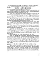
Figure 4.1 illustrates the relationship of the physical layer (L1) and the upper layers
(L2–L3). L1 interfaces the Medium Access Control (MAC) sub-layer of L2 and the
Radio Resource Control (RRC) portion of L3. L1 offers different transport channels to
the MAC and the MAC offers different logical channels to the Radio Link Control
(RLC) sub-layer of L2. Thus, there are Service Access Points (SAPs) between the dif-
ferent layer/sub-layers. A transport channel is characterized by the way information is
transferred over the radio interface. The type of information transferred characterizes a
logical channel.
Two types of physical channels are defined in L1, i.e. Frequency Division Duplex (FDD)
and Time Division Duplex (TDD). The first (FDD) mode is characterized by code, fre-
quency and in the uplink by the relative phase (I/Q); the 2nd (TDD) mode has in addition
a time slot characterization. The Radio Resource Control (RRC) manages L1.
5DGLR5HVRXUFH&RQWURO55&
0HGLXP $FFHVV &RQWURO 0$&
0$&
UhÃpuhry
3K\VLFDOOD\HU
0HDVXUHPHQWV&RQWURO
/
GtvphyÃpuhry
/
/
TrvprÃ6pprÃQv
TrvprÃ6pprÃQv
Figure 4.1 A radio interface protocol architecture around L1.
The data transport services offered to higher layers by L1 occurs through the use of
transport channels via the MAC sub-layer. Table 4.1 illustrates some of the L1 or physi-
cal layer services. Through inter-working (e.g. a UE) provision of compatible bearers is
assured.
86
The UMTS Network and Radio Access Technology
Based on the types of physical channels L1 has two multiple access techniques:
a Direct-Sequence Code Division Multiple Access (DS-CDMA) with the informa-
tion spread within 5 MHz bandwidth, also referred to as Wide-band CDMA
(WCDMA; and
a Time Division Multiple Access (TDMA) + CDMA often denoted as TDMA/
CDMA or TD/CDMA resulting from the extra slotted feature.
Table 4.1 Main Functions of the UTRA Physical Layer
1. Macro-diversity distribution/combining
and soft handover execution
2. Power weighting and combining of
physical channels
3. Error detection on transport channels and
indication to higher layers
4. Modulation and spreading/
demodulation and de-spreading of
physical channels
5. FEC encoding/decoding of transport chan-
nels
6. Frequency and time (chip, bit, slot,
frame) synchronization
7. Multiplexing of transport channels and de-
multiplexing of coded composite transport
channels
8. Radio characteristics measurements
including FER, SIR, interference
power, etc., and indication to higher
layers
9. Rate matching (data multiplexed on DCH) 10. Inner-loop power control
11. Mapping of coded composite transport
channels on physical channels
12. RF processing
The two access schemes afford UTRA two transmission modes, i.e. Frequency Division
Duplex (FDD) corresponding to WCDMA operating with pair bands, and Time Divi-
sion Duplex (TDD) corresponding to TD/CDMA operating with unpaired bands. The
flexibility to operate in either FDD or TDD mode allows efficient spectrum utilization
within the frequency allocation in different regions, e.g. Europe, Asia, etc.
The FDD mode or WCDMA is thus a duplex method where uplink and downlink
transmissions use two different radio frequencies separated, e.g. by 190 MHz. The TDD
mode is a duplex method where uplink and downlink transmissions occur over the same
radio frequency by using synchronized time intervals. In the TDD, time slots in a physi-
cal channel are divided into transmission and reception parts. Information on uplink and
downlink are transmitted reciprocally. The UTRA has QPSK as modulation scheme. In
the WCDMA or FDD mode the spreading (and scrambling) process is closely associ-
ated with modulation. The different UTRA families of codes are:
channelization codes derived with a code tree structure to separate channels from
same the source, and codes to separate different cells;
Table 4.2 illustrates the harmonized parameters of the two UTRA modes.
A 10 ms radio frame divided into 15 slots (2560 chip/slot at the chip rate 3.84 Mcps)
applies to two modes. A physical channel is therefore defined as a code (or number of
codes) and additionally in TDD mode the sequence of time slots completes the defini-
tion of a physical channel. The information rate of the channel varies with the symbol
rate being derived from the 3.84 Mcps chip rate and the spreading factor.
We derive the symbol rate from the 3.84 Mcps chip rate and the spreading factor to ob-
tain a variable rate in the channel. The information rate of the channel, e.g. varies with
The UTRA Physical Layer Design 87
spreading factors from 256 to 4 for FDD uplink, from 512 to 4 for FDD downlink; and
from 16 to 1 for TDD uplink and downlink. Consequently, modulation symbol rates
vary from 960 k symbols/s to 15 k symbols/s (7.5 k symbols/s) for FDD uplink (down-
link) respectively, and for TDD the momentary modulation symbol rates varies from
3.84 M symbols/s to 240 k symbols/s.
The UTRA has QPSK as modulation scheme. In the WCDMA or FDD mode the
spreading (and scrambling) process is closely associated with modulation. The different
UTRA families of codes are:
Table 4.2 UTRA FDD and TDD Harmonized Parameters
Parameters UTRA TDD UTRA FDD
Multiple access
TDMA, CDMA (inherent FDMA)
CDMA (inherent FDMA)
Duplex method TDD FDD
Channel spacing and carrier
chip rate
5 MHz (nominal) and 3.84 Mcps
Time slot and frame length 15 slots/frame and 10 ms
Spreading factor 1,2,4,8,16 4…512
Channel allocation Slow and fast DCA supported No DCA required
Types of burst Traffic bursts, random access
and synchronization burst
DTX time mask defined,
burst not applicable
Multi-rate concept Multi-code, multi-slot and or-
thogonal variable spreading
Multi-code and orthogonal
variable spreading
Forward error correction
(FEC) codes
Convolutional coding R=1/2 or 1/3 constraint length K=9,
turbo coding (8-state PCCC R=1/3) or service specific coding
Interleaving Inter-frame interleaving (10, 20, 40 and 80 ms)
Modulation QPSK
Detection Coherent, based on midamble Coherent, based on pilot
symbols
Dedicated channel power
control
UL: open loop; 100 or 200 Hz
DL: closed loop; rate 800 Hz
Fast closed loop;
rate = 1500 Hz
Intra-frequency handover Hard handover Soft and softer handovers
Inter-frequency handover Hard handover
Intra-cell interference can-
cellation
Support for joint detection Support for advanced re-
ceivers at base station
gold codes with 10 ms period (38400 chips at 3.84 Mcps) used in the FDD mode,
with the actual code itself length 2
18
–1 chips, and scrambling codes of length 16
used in the TDD mode;
User Equipment (UE) separating codes: gold codes with 10 ms period, or alternatively
S(2) codes 256 chip period for FDD mode, and codes with period of 16 chips and mid-
amble sequences of different length depending on the environment for the TDD mode.
The key physical layer procedures involved with UTRA operation are:
power control, with both inner loop and slow quality loop for FDD mode, and for
TDD mode open loop in uplink and inner loop in downlink;
cell search operation.
88
The UMTS Network and Radio Access Technology
Measurements reported to higher layers and network containing radio characteristics
like FER, SIR, interference power, etc. are:
handover measurements within UTRA, e.g. determination of relative strength of a
cell. In the FDD mode, identification of timing relation between cells to support
asynchronous soft handover;
other measurement procedures are: preparation for HO to GSM900/1800/1900; UE
procedures before random access process; and procedures for Dynamic Channel
Allocation (DCA) in the TDD mode.
4.2 D
EDICATED AND
C
OMMON
T
RANSPORT
C
HANNELS
Transport channels are defined by how and with what features data is transferred over
the air interface. The generic classification of transport channels includes two groups,
i.e. dedicated and common channels. The first group uses inherent UE addressing, while
the second uses explicit UE addressing when addressing is required.
4.2.1 Dedicated Transport Channels
There is primarily one transport Dedicated Channel (DCH) for up- or downlink in the
FDD and TDD modes, which is used to carry user or control information between the
UTRAN and a UE. The DCH is transmitted over the entire cell or over only a part of
the cell using, e.g. beam-forming antennas.
4.2.2 Common Transport Channels
While the intrinsic function of each common transport channel may not necessarily be
identical in the FDD and TDD modes, both sets have basically the same function and
acronym. Table 4.3 summarizes the essential definitions for the two modes.
Table 4.3 Summary of Common Transport Channels
FDD mode TDD mode
BCH – Broadcast Channel BCH – Broadcast Channel
Downlink transport channel that is used to broadcast system- and cell-specific information.
The BCH is always transmitted over the entire cell and has a single transport format.
FACH – Forward Access Channel FACH – Forward Access Channel(s)
Downlink transport channel used to carry control information to a mobile station when the
system knows the cell location of the mobile station. In the FDD, it can be transmitted over the
entire cell or over only a part of the cell using, e.g. beam-forming antennas, and it can also be
transmitted using slow power control. In the TDD may carry short user packets.
PCH – Paging Channel PCH – Paging Channel
Downlink transport channel transmitted always over the entire cell, used to carry control in-
formation to a mobile station when the system does not know the location cell of the mobile
station. In the FDD mode transmission of the PCH is associated with the transmission of
physical-layer generated paging indicators, to support efficient sleep-mode procedures.
RACH – Random Access Channel RACH – Random Access Channel
Uplink transport channel, always received from the entire cell, used to carry control informa-
tion from the mobile station. In FDD, the RACH is characterized by a collision risk and by
using open loop power control for transmission. In TDD it may also carry short user packets.
The UTRA Physical Layer Design 89
CPCH – Common Packet Channel USCH – Uplink Shared Channel
Uplink transport channel associated with a dedi-
cated channel on the downlink, which provides
power control and CPCH control commands
(e.g. emergency stop). It is characterized by
initial collision risk and by using inner loop
power control for transmission.
Uplink transport channel shared by several
UEs carrying dedicated control or traffic
data.
DSCH – Downlink Shared Channel DSCH - Downlink Shared Channel
Downlink transport channel shared by several UEs carrying dedicated control or traffic data. In
FDD it is associated with one or several downlink DCH(s). It may be transmitted over the
entire cell or over only a part of the cell using e.g. beam-forming antennas.
Both FDD and TDD have a similar number of transport channels; however, the FDD
mode does not have an Uplink Shared Channel (USCH) and the TDD mode does not
have a Common Packet Channel (CPCH).
The CPCH transport channel in FDD performs essential power control commands,
which may not be required in TDD. Likewise, the USCH transport channel performs
essential commands in TDD, which may not be required in FDD.
4.3 C
ONFIGURATION OF
FDD P
HYSICAL
C
HANNELS
Physical channels in FDD inherit primarily a layered structure of radio frames and time
slots. A radio frame is a processing unit consisting of 15 slots with a length of 38 400
chips, and slot is a unit consisting of fields containing bits with a length of 2560 chips.
The slot configuration varies depending on the channel bit rate of the physical channel;
thus, the number of bits per slot may be different for different physical channels and
may, in some cases, vary with time. The basic physical resource is the code/frequency
plane, and on the uplink, different information streams may be transmitted on the I and
Q branches. Thus, a physical channel corresponds to a specific carrier frequency, code,
and on the uplink there is in addition a relative phase (0 or
p
/2) element.
4.3.1 Uplink and Downlink Modulation
The uplink modulation uses a chip rate of 3.84 Mcps, where the complex-valued chip
sequence generated by the spreading process has QPSK modulation as seen in
Figure 4.2. The pulse-shaping characteristics are described in [3].
T
XS
DT
XS
SrT
XS
p
w
8yrhyrq
puvÃrrpr
sÃrhqvt
rhv
v
w
Qyr
uhvt
Qyr
uhvt
Tyv
rhyÃÉ
vht
h
U
'/
DU
'/
SrU
'/
Figure 4.2 Uplink/downlink modulation process.
90
The UMTS Network and Radio Access Technology
The downlink modulation also has a chip rate of 3.84 Mcps, with a QPSK modulated
complex-valued chip sequence generated by the spreading process. Figure 4.2 does also
represent the downlink modulation process. However, the DL pulse-shaping
characteristics are described in [4].
4.3.2 Dedicated Uplink Physical Channels
The two types of uplink dedicated physical channels, i.e. Dedicated Physical Data
Channel (DPDCH) and Dedicated Physical Control Channel (DPCCH) are I/Q code
multiplexed within each radio frame. The uplink DPDCH carries the DCH transport
channel, while the uplink DPCCH carries L1 control information such as: known pilot
bits to support channel estimation for coherent detection, Transmit Power Control
(TPC) commands, Feedback Information (FBI), and an optional Transport Format
Combination Indicator (TFCI).
The TFCI informs the receiver about the instantaneous transport format combination of
the transport channels mapped to the uplink DPDCH transmitted simultaneously. There
is one and only one uplink DPCCH on each radio link; however, there may be zero,
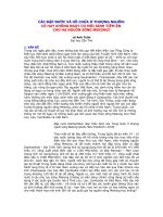
one, or several uplink DPDCHs on each radio link. Figure 4.3 illustrates the frame
structure of the uplink dedicated physical channels, where each frame has 10 ms length
split into 15 slots (T
slot
) of 2560 chips length, corresponding to one power control
period.
Parameter k in Figure 4.3 determines the number of bits per uplink DPDCH slot. It is
related to the spreading factor defined as SF = 256/2
k
, which may range from 256 down
to 4. The SF in the uplink DPCCH is always equal to 256 corresponding to 10 bits per
uplink DPCCH slot. Table 4.4 illustrates the exact number of bits in the uplink DPDCH,
while Table 4.5 shows the different uplink DPCCH fields (i.e. N
pilot
, N
TFCI
, N
FBI
, and
N
TPC
). The pilot patterns are given Table 4.6 and the TPC bit pattern is given in Table
4.8. Upper layers configure the slot format. The channel symbol rate and SF for all
cases in Table 4.5 are 15 and 256, respectively. Channel bit and symbol rates illustrated
in Tables 4.4 and Table 4.5 reflect rates before spreading.
Qvy)ÃI
SLORW
Ãiv UQ8)ÃI
73&
Ãiv
U
VORW
Ã2Ã!$%Ãpuvà Ãiv
ÃhqvÃshr)ÃU
I
Ã2Ã Ã
'3'&+
'3&&+
A7D)ÃI
)%,
ÃivUA8D)ÃI
7)&,
Ãiv
U
VORW
Ã2Ã!$%ÃpuvÃI
GDWD
Ã2Ã !
N
Ãiv
Ã
x2%
9hh)ÃI
GDWD
Ãiv
Tyà #TyÃ$Tyà TyÃ
Figure 4.3 Uplink frame structure DPDCH/DPCCH.
The UTRA Physical Layer Design 91
The FBI bits (S field and D field) support the techniques requiring feedback from the
UE to the UTRAN access point, including closed loop mode transmit diversity and Site
Selection Diversity Transmission’ (SSDT). The open SSDT signalling uses the S field
and the closed loop mode transmit diversity signalling uses the D field. The S field con-
sists of 0, 1 or 2 bits while the D field consists of 0 or 1 bit. Table 4.5 shows the total
FBI field size, i.e. the N
FBI
. Simultaneous use of SSDT power control and closed loop
mode transmit diversity requires that the S field consists of 1 bit. The use of the FBI
fields is described in detail in [5].
Table 4.4 DPDCH Fields
Slot
format #i
Channel bit
rate (kbps)
Channel symbol
rate (ksps)
SF Bits/frame Bits/slot N
data
0 15 15 256 150 10 10
1 30 30 128 300 20 20
2 60 60 64 600 40 40
3 120 120 32 1200 80 80
4 240 240 16 2400 160 160
5 480 480 8 4800 320 320
6 960 960 4 9600 640 640
There are two types of uplink dedicated physical channels; those that include TFCI (e.g.
for several simultaneous services) and those that do not include TFCI (e.g. for fixed-rate
services). These types are reflected by the duplicated rows of Table 4.5. It is the UT-
RAN that determines if a TFCI should be transmitted and it is mandatory for all UEs to
support the use of TFCI in the uplink. The mapping of TFCI bits onto slots is described
in [3]. In compressed mode, DPCCH slot formats with TFCI fields are changed. There
are two possible compressed slot formats for each normal slot format. They are labelled
A and B and the selection between them is dependent on the number of slots that are
transmitted in each frame in compressed mode.
Table 4.5 DPCCH Fields
Slot
format #i
Channel bit
rate (kbps)
Bits/
frame
Bits/s
lot
N
pilot
N
TP
C
N
TFCI
N
FBI
Slots/
frame
0 15 150 10 6 2 2 0 15
0A 15 150 10 5 2 3 0 10
–
14
0B 15 150 10 4 2 4 0 8–9
1 15 150 10 8 2 0 0 8–15
2 15 150 10 5 2 2 1 15
2A 15 150 10 4 2 3 1 10–14
2B 15 150 10 3 2 4 1 8–9
3 15 150 10 7 2 0 1 8–15
4 15 150 10 6 2 0 2 8–15
5 15 150 10 5 1 2 2 15
5A 15 150 10 4 1 3 2 10–14
5B 15 150 10 3 1 4 2 8–9
92
The UMTS Network and Radio Access Technology
The pilot bit patterns are described in Tables 4.6 and 4.8. The shadowed column part of
pilot bit pattern is defined as FSW, which can be used to confirm frame synchroniza-
tion. (The value of the pilot bit pattern other than FSWs shall be ‘1’.)
Table 4.6 Pilot Bit Patterns for Uplink DPCCH with N
pilot
= 3, 4, 5 and 6
Slot N
pilot
= 3 N
pilot
= 4 N
pilot
= 5 N
pilot
= 6
%LW
0 1 1 1 1 1 1 1 1 1 1 1 0 1 1 1 1 1 0
1 0 0 1 1 0 0 1 0 0 1 1 0 1 0 0 1 1 0
2 0 1 1 1 0 1 1 0 1 1 0 1 1 0 1 1 0 1
3 0 0 1 1 0 0 1 0 0 1 0 0 1 0 0 1 0 0
4 1 0 1 1 1 0 1 1 0 1 0 1 1 1 0 1 0 1
5 1 1 1 1 1 1 1 1 1 1 1 0 1 1 1 1 1 0
6 1 1 1 1 1 1 1 1 1 1 0 0 1 1 1 1 0 0
7 1 0 1 1 1 0 1 1 0 1 0 0 1 1 0 1 0 0
8 0 1 1 1 0 1 1 0 1 1 1 0 1 0 1 1 1 0
9 1 1 1 1 1 1 1 1 1 1 1 1 1 1 1 1 1 1
10 0 1 1 1 0 1 1 0 1 1 0 1 1 0 1 1 0 1
11 1 0 1 1 1 0 1 1 0 1 1 1 1 1 0 1 1 1
12 1 0 1 1 1 0 1 1 0 1 0 0 1 1 0 1 0 0
13 0 0 1 1 0 0 1 0 0 1 1 1 1 0 0 1 1 1
14 0 0 1 1 0 0 1 0 0 1 1 1 1 0 0 1 1 1
Table 4.7 presents the relationship between the TPC bit pattern and transmitter power
control command.
Table 4.7 TPC Bit Pattern
TPC bit pattern
N
TPC
= 1 N
TPC
= 2
Transmitter power
control command
1
0
11
00
1
0
While there is only DPCCH per radio link, several parallel DPDCHs using different
channelization codes [4] can be transmitted for the multi-code operation in the uplink
dedicated physical channels.
Table 4.8 Pilot Bit Patterns for Uplink DPCCH with N
pilot
= 7 and 8
Slot # N
pilot
= 7 N
pilot
= 8
%LW
0 1 1 1 1 1 0 1 1 1 1 1 1 1 1 0
1 1 0 0 1 1 0 1 1 0 1 0 1 1 1 0
2 1 0 1 1 0 1 1 1 0 1 1 1 0 1 1
3 1 0 0 1 0 0 1 1 0 1 0 1 0 1 0
4 1 1 0 1 0 1 1 1 1 1 0 1 0 1 1
5 1 1 1 1 1 0 1 1 1 1 1 1 1 1 0
6 1 1 1 1 0 0 1 1 1 1 1 1 0 1 0
7 1 1 0 1 0 0 1 1 1 1 0 1 0 1 0
The UTRA Physical Layer Design 93
8 1 0 1 1 1 0 1 1 0 1 1 1 1 1 0
9 1 1 1 1 1 1 1 1 1 1 1 1 1 1 1
10 1 0 1 1 0 1 1 1 0 1 1 1 0 1 1
11 1 1 0 1 1 1 1 1 1 1 0 1 1 1 1
12 1 1 0 1 0 0 1 1 1 1 0 1 0 1 0
13 1 0 0 1 1 1 1 1 0 1 0 1 1 1 1
14 1 0 0 1 1 1 1 1 0 1 0 1 1 1 1
4.3.2.1 Spreading DPCCH/DPDCH
In the uplink spreading principle of DPCCH and DPDCHs real-valued sequences of +1
and –1 represent the binary values ‘0’ and ‘1’, respectively. We spread the DPCCH to
the chip rate by the channelization code c
c
, and the nth DPDCH (or DPDCH
n)
to the
chip rate by the channelization code c
d,n
. As illustrated in Figure 4.4, we can transmit
one DPCCH and up to six parallel DPDCHs simultaneously, i.e. 1
n
6 [8].
,
S
M
F
G
b
G
6
'3&+Q
,M4
'3'&+
4
F
G
b
G
'3'&+
F
G
b
G
'3'&+
F
G
b
G
'3'&+
F
G
b
G
'3'&+
F
G
b
G
'3'&+
F
F
b
F
'3&&+
S
6
Figure 4.4 Spreading for uplink DPCCH and DPDCHs.
After channelization, gain factors
b
c
for DPCCH and
b
d
for all DPDCHs weight the
real-valued spread signals, where at every instant in time, at least one of the values
b
c
and
b
d
have the amplitude 1.0. Likewise after the weighting, we sum the stream of real-
valued chips on the I- and Q-branches and then treat them as a complex-valued stream
of chips. After we scramble these streams by the complex-valued scrambling code
S
dpch.n
, the scrambling code application aligns with the radio frames, i.e. the first scram-
bling chip corresponds to the beginning of a radio frame.
94
The UMTS Network and Radio Access Technology
Table 4.9 illustrates quantization steps of the
b
-values quantized into 4 bit words. After
the weighting, we sum the stream of real-valued chips on the I- and Q-branches and
then treat them as a complex-valued stream of chips. After we scramble these streams
by the complex-valued scrambling code S
dpch,n
. The scrambling code application aligns
with the radio frames, i.e. the first scrambling chip corresponds to the beginning of a
radio frame.
Table 4.9 The Quantization of the Gain Parameters
Signalling values for b
c
and
b
d
Quantized amplitude ratios
b
c
and b
d
15 1.0
14 0.9333
13 0.8666
12 0.8000
11 0.7333
10 0.6667
9 0.6000
8 0.5333
7 0.4667
6 0.4000
5 0.3333
4 0.2667
3 0.2000
2 0.1333
1 0.0667
0 Switch off
4.3.3 Common Uplink Physical Channels
4.3.3.1 Physical Random Access Channel - PRACH
The PRACH carries the Random Access Channel (RACH).
$ !Ãpuv
hqvÃshr)Ã Ã hqvÃshr)Ã Ã
6pprÃy
ShqÃ6pprÃUhvv
ShqÃ6pprÃUhvv
ShqÃ6pprÃUhvv
ShqÃ6pprÃUhvv
Figure 4.5 RACH access slot numbers and spacing.
The UTRA Physical Layer Design 95
4.3.3.1.1 The Random-access Transmission Structure
The random-access transmission uses a slotted ALOHA technique with fast acquisition
indication. The UE can start the random-access transmission at the beginning of a num-
ber of well-defined time intervals, denoted access slots as illustrated in Figure 4.5.
There are 15 access slots per two frames and they are spaced 5120 chips apart. The in-
formation about the type of access slots available for random-access transmission
comes from the upper layers.
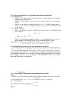
Figure 4.6 illustrates the random-access transmission structure, where the transmission
consists of one or several preambles of length 4096 chips and a message of length
10 ms or 20 ms. Each preamble has 256 repetitions of 16 chips signature. Thus, there is
a maximum of 16 available signatures, see [4] for more details.
0HVVDJHSDUW
3UHDPEOH
FKLSV
ÃÃ ÃhqvÃshr
3UHDPEOH 3UHDPEOH
0HVVDJHSDUW
!ÃÃÃhqvÃshr
Figure 4.6 Structure of the random-access transmission.
4.3.3.1.2 The RACH Message Part
Figure 4.7 illustrates the random-access message part radio frame structure, where the
10 ms message part radio frame is split into 15 slots, each having a length T
slot
= 2560
chips. Furthermore, each slot consists of two parts, i.e. a data part to which the RACH
transport channel is mapped and a control part that carries Layer 1 control information;
they are transmitted in parallel.
3LORW
1
SLORW
ELWV
'DWD
1
GDWD
ELWV
6ORW 6ORW 6ORWL 6ORW
7
VORW
FKLSV
N
ELWVN
0HVVDJHSDUWUDGLRIUDPH7
5$&+
PV
'DWD
&RQWURO
7)&,
1
7)&,
ELWV
Figure 4.7 Random-access message part radio frame structure.
96
The UMTS Network and Radio Access Technology
A 10 ms message part consists of one message part radio frame, while a 20 ms message
part consists of two consecutive 10 ms message part radio frames. The message part
length can be determined from the used signature and/or access slot, as configured by
higher layers. Table 4.10 illustrates data and control fields of the random access mes-
sage.
Table 4.10 Random Access Message Data and Control Fields
Slot
format #i
Channel bit
rate (kbps)
Channel symbol
rate (ksps)
SF Bits/
frame
Bits/
slot
N
pilot
N
data
0 15 15 256 150 10 10
1 30 30 128 300 20 20
2 60 60 64 600 40 40
3 120 120 32 1200 80 80
Control fields N
TFCI
0 15 15 256 150 10 8 2
The data part consists of 10 × 2
k
bits, where k = 0,1,2,3. This corresponds to a spreading
factor of 256, 128, 64, and 32 for the message data part, respectively.
The control part consists of 8 known pilot bits to support channel estimation for coher-
ent detection and 2 TFCI bits. This corresponds to a spreading factor of 256 for the
message control part. The pilot bit pattern is described in Table 4.11. The total number
of TFCI bits in the random-access message is 15 × 2 = 30.
The TFCI of a radio frame indicates the transport format of the RACH transport channel
mapped to the simultaneously transmitted message part radio frame. In the case of a
20 ms PRACH message part, the TFCI is repeated in the second radio frame.
Table 4.11 Pilot Bit Patterns for RACH Message Part with N
pilot
= 8
Slot # N
pilot
= 8
Bit # 0 1 2 3 4 5 6 7
0 1 1 1 1 1 1 1 0
1 1 0 1 0 1 1 1 0
2 1 0 1 1 1 0 1 1
3 1 0 1 0 1 0 1 0
4 1 1 1 0 1 0 1 1
5 1 1 1 1 1 1 1 0
6 1 1 1 1 1 0 1 0
7 1 1 1 0 1 0 1 0
8 1 0 1 1 1 1 1 0
9 1 1 1 1 1 1 1 1
10 1 0 1 1 1 0 1 1
11 1 1 1 0 1 1 1 1
12 1 1 1 0 1 0 1 0
13 1 0 1 0 1 1 1 1
14 1 0 1 0 1 1 1 1
The UTRA Physical Layer Design 97
4.3.3.2 Physical Common Packet Channel (PCPCH)
The Physical Common Packet Channel (PCPCH) carries the CPCH. The CPCH trans-
mission is based on the Digital Sense Multiple Access – Collision Detection (DSMA-
CD) technique with fast acquisition indication. The UE can start transmission at the
beginning of a number of well-defined time-intervals, relative to the frame boundary of
the received BCH of the current cell. The access slot timing and structure are identical
to those defined for the RACH. Figure 4.8 illustrates the structure of the CPCH access
transmission. The PCPCH access transmission consists of one or several Access Pream-
bles [A-P] of length 4096 chips, one Collision Detection Preamble (CD-P) of length
4096 chips, a DPCCH Power Control Preamble (PC-P) which is either 0 slots or 8 slots
in length, and a message of variable length Nx10 ms.
#(%Ãpuv
3
3
3
M
3
M
8yyvvÃ9rrpv
Qrhiyr
6pprÃQrhiyr Ã8yÃQh
9hhÃh
ÃÃ'Ãy
I Ãrp
HrhtrÃQh
Figure 4.8 Structure of the CPCH access transmission.
4.3.3.2.1 CPCH Access –Power Control and Detection Preamble Parts
Like in the RACH, the access CPCH preamble uses signature sequences, but the
number of sequences can be lower. The scrambling codes may differ from the gold
codes segment used in the RACH or could be the same scrambling code.
Table 4.12 defines the DPCCH fields form the CPCH PC-P part. The power control
preamble length parameter takes the values 0 or 8 slots, as set by the higher layers.
When the power control preamble length is set to 8 slots, pilot bit patterns from slot
#0 to slot #7 defined in Table 4.8 shall be used for CPCH PC-P.
Table 4.12 DPCCH Fields for CPCH Power Control Preamble Segment
Slot
format
#
i
Chan-
nel bit
rate
(kbps)
Channel
symb. rate
(ksps)
SF Bits/
Fram
e
Bits/
Slot
N
pilot
N
TPC
N
TFCI
N
FBI
0 15 15 256 150 10 6 2 2 0
1 15 15 256 150 10 8 2 0 0
2 15 15 256 150 10 5 2 2 1
3 15 15 256 150 10 7 2 0 1
4 15 15 256 150 10 6 2 0 2
5 15 15 256 150 10 5 1 2 2
98
The UMTS Network and Radio Access Technology
Also like in the RACH, the detection CPCH preamble uses signature sequences.
However, the scrambling code set differs from the gold code segment used to form
the RACH scrambling code.
4.3.3.2.2 CPCH Message Part
With similar message part structure of the RASH, each CPCH message part consists of
up to N_Max_frames
1
10 ms frames, with a 10 ms frame split into 15 slots, each having
T
slot
= 2560 chips length. In addition, every slot consists of a data part that carries higher
layer information and a control part that carries Layer 1 control information. The data
and control parts are transmitted in parallel.
The DPDCH field entries defined in Table 4.4 apply also to the data part of the CPCH
message part. The control part of the CPCH message part has a spreading factor of 256,
and it uses the same slot format as the control part of the CPCH PC-P. The pilot bit pat-
terns defined in Tables 4.6 and 4.8 apply also to the pilot bit patterns of the CPCH mes-
sage part.
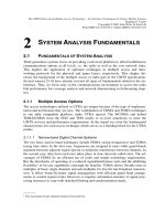
Figure 4.9 illustrates the uplink common packet physical channel frame structure. Each
frame of length 10 ms is split into 15 slots having T
slot
= 2560 chips length correspond-
ing to one power-control period.
Qvy
I
SLORW
Ãiv
9hh
I
GDWD
Ãiv
TyÃÆ TyÃÆ TyÃÆv TyÃÆ #
U
VORW
Ã2Ã!$%Ãpuvà !
N
ÃivÃx2%
ÃhqvÃshr)ÃU
I
Ã2Ã Ã
'DWD
&RQWURO
A7D
ÃI
)%,
Ãiv
UA8D
I
7)&,
Ãiv
UQ8
ÃI
73&
Ãiv
Figure 4.9 Frame structure for uplink data and control parts associated with PCPCH.
The data part consists of 10 × 2
k
bits, where k = 0, 1, 2, 3, 4, 5, 6, corresponding to
spreading factors of 256, 128, 64, 32, 16, 8, 4, respectively.
4.3.3.3 Spreading Common Uplink Physical Channels
4.3.3.3.1 PRACH
The PRACH preamble part consists of a complex-valued code and the message part
includes the data and control parts, Figure 4.10 illustrates its spreading principle. In the
message part, real-value sequences represent the binary control and data parts i.e. the
binary value ‘0’ maps to the real value +1, while the binary value ‘1’ maps to the real
_______
1
N_Max_frames is a higher layer parameter.
The UTRA Physical Layer Design 99
value –1. The channelization code c
c
spreads the control part, while channelization code
c
d
spreads the data part.
After channelization, gain factor
b
c
for the control part and
b
d
for the data part weight
the real-valued spread signals, where at least every instant in time one of the value
b
c
and
b
d
have the amplitude 1.0. Table 4.9 illustrates quantization steps of the
b
-values
quantized into 4 bit words.
Once the weighting takes place, we treat the stream of real-valued chips on the I- and
Q-branches as a complex-valued stream of chips. Then the complex-valued scrambling
code S
r-msg,n
scrambles this complex-valued signal. The 10 ms scrambling code applica-
tion aligns with the 10 ms message part radio frames, i.e. the first scrambling chip cor-
responds to the beginning of a message part radio frame [8].
w
b
F
p
F
p
G
b
G
T
UPVJQ
DwR
QS68CÃrhtr
pyÃh
QS68CÃrhtr
qhhÃh
R
D
6
Figure 4.10 Spreading of PRACH message part.
4.3.3.3.2 PCPCH
As in the PRACH, the PCPCH preamble part consists of a complex-valued code, and
the PCPCH message part includes data and control parts, Figure 4.11 illustrates its
spreading principle.
w
b
F
p
F
p
G
b
G
T
FPVJQ
DwR
Q8Q8CÃrhtr
pyÃh
Q8Q8CÃrhtr
qhhÃh
R
D
6
Figure 4.11 Spreading of PCPCH message part.
In the message part, real-value sequences represent the binary control and data parts, i.e.
the binary value ‘0’ maps to the real value +1, while the binary value ‘1’ maps to the
100
The UMTS Network and Radio Access Technology
real value –1. The channelization code c
c
spreads the control part, while channelization
code c
d
spreads the data part. Channelization and weighting follows the same pattern as
in the PRACH.
4.3.4 Uplink Channelization Codes
The Orthogonal Variable Spreading Factor (OVSF) channelization codes preserve or-
thogonality between a user’s different physical channels. A tree illustrated in Figure
4.12 defines these codes.
6)
6)
6)
&
pu Ã
&
pu!Ã
&
pu! Ã
&
pu#Ã
&
pu# Ã
&
pu#!Ã
&
pu#"Ã
««
Figure 4.12 Orthogonal Variable Spreading Factor (OVSF) code-tree generation.
The channelization codes in the OVSF tree have a unique description as C
ch,SF,k
, where
SF is the spreading factor of the code and k is the code number, 0
k
SF – 1. Each
level in the code tree defines channelization codes of length SF, corresponding to a
spreading factor of SF. From [8] the generation method for the channelization code is
defined as:
FK
& =
FK
FK FK
FK FK
FK
&
&&
&&
&
ÎÞ
ÎÞ
ÎÞ
==
Ïß
Ïß
Ïß
-
-
Ïß
Ðà
Ðà
Ðà
()
()
()
()
()()
()()
FK
FK FK
FK
FK FK
FK FK
FK
FK
FK
FK FK
FK
Q
Q
QQQ
Q
FK
QQ QQ
FK
FK
&
&&
&
&&
&
&&
&&&
&&
&
&
&
+
+
+
+
++
--
-
++
-
-
ÎÞ
Ïß
-
Ïß
Ïß
Ïß
Ïß
=
-
Ïß
Ïß
Ïß
Ïß
Ïß
Ïß
Ïß
Ðà
FK
&
-
ÎÞ
Ïß
Ïß
Ïß
Ïß
Ïß
Ïß
Ïß
Ïß
Ïß
Ïß
Ïß
-
Ïß
Ðà
The UTRA Physical Layer Design 101
The leftmost value in each channelization code word corresponds to the chip transmit-
ted first in time.
4.3.4.1 DPCCH/DPDCH Code Allocation
According to [8] for the DPCCH and DPDCHs the following applies: the DPCCH is
always a code c
c
= C
ch,256,0
as spread; and when we transmit only one DPDCH, the
DPDCH
1
has code c
d,1
= C
ch,SF,k
as spread, where SF is the spreading factor of DPDCH
1
and k = SF/4. However, when we transmit more than one DPDCH, all DPDCHs have
spreading factors equal to 4. The DPDCH
n
is spread by the code c
d,n
= C
ch,4,k
, where
k = 1 if n
³
{1, 2}, k = 3 if n
³
{3, 4}, and k = 2 if n
³
{5, 6}.
4.3.4.2 PRACH Message Part Code Allocation
The preamble signature s, 0
s
15, points to one of the 16 nodes in the code tree that
corresponds to channelization codes of length 16. To spread the message part we use
the sub-tree below a specified node, while to spread the control part we use the chan-
nelization code c
c
with SF = 256 in the lowest branch of the sub-tree, i.e. c
c
= C
ch,256,m
where m = 16
s + 15. The data part uses any of the channelization codes from spread-
ing factor 32 to 256 in the upper-most branch of the sub-tree. More exactly, we spread
the data part by channelization code c
d
= C
ch,SF,m
, SF is the data part spreading factor
and m = SF
s/16 [8].
4.3.4.3 PCPCH Message Part Code Allocation
For the control part and data part the following applies: the control part has always code
c
c
=C
ch,256,0
as spread; and the data part has code c
d
= C
ch,SF,k
as spread, where SF is the
spreading factor of the data part and k = SF/4. The data part may use the code from
spreading factor 4 to 256, and a UE can increase SF during a message transmission on
frame by frame basis [8].
Finally, the same channelization code of the message control part applies to the PCPCH
power control preamble.
4.3.5 Uplink Scrambling Codes
All uplink physical channels use a complex-valued scrambling code. While either long
or short scrambling codes apply to the DPCCH/DPDCH, to the PRACH and PCPCH
message parts only long scrambling codes apply. Higher layers assign the 2
24
long and
2
24
short uplink scrambling codes.
4.3.5.1 Long Scrambling Sequence
The long scrambling sequences c
long,1,n
and c
long,2,n
result from the position wise modulo
2 sum of 38 400 chip segments and two binary m sequences generated by means of two
generator polynomials of degree 25. The 1st m sequences, i.e. x comes from the primi-
tive (over GF (2)) polynomial X
25
+ X
3
+ 1; while the 2nd m sequences, i.e. y comes
from the polynomial X
25
+ X
3
+ X
2
+ X + 1. The resulting sequences constitute a seg-
102
The UMTS Network and Radio Access Technology
ment set of gold sequences, where the sequence c
long,2,n
is a 16 777 232 chip shifted
version of the sequence c
long,1,n
[8]. Figure 4.13 illustrates a configuration of long uplink
scrambling sequence generator.
For completeness in the following we include an extract of the long scrambling se-
quence definition from [8]. Where n
23
…n
0
= 24 bit binary representation of the scram-
bling sequence number n with n
0
as the least significant bit, x sequence which depends
on the chosen scrambling sequence number n is denoted x
n
, x
n
(i) and y(i) denote the ith
symbol of the sequence x
n
and y, respectively. Then m sequences x
n
and y can be de-
fined as:
QQ Q Q Q
[Q[Q[ Q[ Q[== = = =K
Ã
\\ \ \=== = =L
where x
n
(0) and y(0) are the initial conditions.
The recursive definition of subsequent symbols include:
PRG
QQQ
[L [L [L L+= ++ = -
K
PRG \L \L \L \L \L L+=++++++ = -
K
The binary gold sequence z
n
can be defined as:
PRG
]L [L \L L=+ = -
K
then the real valued gold sequence Z
n
is defined by:
LI
IRU
LI
Q
Q
Q
]L
=L L
]L
+=
Ñ
==-
Ò
-=
Ó
K
Now, the real-valued long scrambling sequences c
long,1,n
and c
long,2,n
are defined as:
ORQJ
FL=LL== -K
and
ORQJ
PRG
FL=L L=+ - = -K
Finally, we define the complex-valued long scrambling sequence C
long,n
, as
()
()
( )
ORQJ ORQJ ORQJ
L
QQ Q
&LF L M F L=+-
Ïß
Ðà
where i = 0,1,…,2
25
– 2 and
Ð
à
denotes rounding to the nearest lower integer.
The UTRA Physical Layer Design 103
F
ORQJQ
F
ORQJQ
06%
/6%
Figure 4.13 Configuration of the uplink long scrambling sequence generator.
4.3.5.2 Short Scrambling Sequence
The short scrambling sequences c
short,1,n
(i) and c
short,2,n
(i) originate from a family se-
quence of periodically extended S(2) codes, where n
23
n
22
…n
0
= 24 bit binary represen-
tation of the code number n. We obtain the nth quaternary S(2) sequence z
n
(i), 0
n
1677721 by modulo 4 addition of three sequences, a quaternary sequence a(i) and two
binary sequences b(i) and d(i), where the initial loading of the three sequences comes
from the code number n. The sequence z
n
(i) of length 255 results from the following
relation:
PRG
Q
]L DL EL GL L=+ + =K
where we obtain the quaternary sequence a(i) recursively through the polynomial g
0
(x)=
x
8
+ x
5
+ 3x
3
+ x
2
+ 2x + 1 as
PRG DQ=+
PRG
L
DL Q L==K
PRG DL DL DL DL DL DL L=-+-+-+-+- =K
and the binary sequence b(i) comes also recursively from the polynomial g
1
(x)=
x
8
+ x
7
+ x
5
+ x + 1 as
PRG
L
EL Q L
+
==K
PRG EL EL EL EL EL L=-+-+-+- = K
and the binary sequence d(i) is again generated recursively by the polynomial g
2
(x)=
x
8
+ x
7
+ x
5
+ x
4
+ 1 as
104
The UMTS Network and Radio Access Technology
PRG
L
GL Q L
+
==K
PRG GL GL GL GL GL L=-+-+-+- = K
We extend the sequence z
n
(i) to length 256 chips by setting z
n
(255) = z
n
(0).
Table 4.13 defines the mapping from z
n
(i) to the real-valued binary sequences c
short,1,n
(i)
and c
short,2,n
(i), i = 0,1,…,255.
Table 4.13 Mapping from z
n
(i) to c
short,1,n
(i) and c
short,2,n
(i), i = 0,1,…,255
z
n
(i) c
short,1,n
(i) c
short,2,n
(i)
0 +1 +1
1 –1 +1
2 –1 –1
3 +1 –1
Finally, we define the complex-valued short scrambling sequence C
short,n
, as:
() ( )
( )
( )
VKRUW VKRUW VKRUW
PRG PRG
L
QQ Q
&LF L M F L=+-
Ïß
Ðà
Figure 4.14 illustrates an implementation of the short scrambling sequence generator for
the 255 chip sequence extension by one chip.
&
#
qÃQÃhqqvv
qv
!"$%
!
qÃ!
&
#
iv
!"$%
!
qÃ!
qÃ#
yvyvphv
Q
v
& # !"$%
qÃ#
0DSSHU
p
VKRUWQ
v
hv
p
VKRUWQ
v
Figure 4.14 255 chip sequence uplink short scrambling sequence generator.
4.3.5.3 Scrambling Codes in Uplink Dedicated Physical Channels
The uplink DPCCH/DPDCH may use either long or short scrambling codes with differ-
ent constituent codes in each case.
The UTRA Physical Layer Design 105
From [8], when using long scrambling codes we define the nth uplink DPCCH/DPDCH
scrambling code denoted S
dpch,n
, as
GSFK ORQJ
6L&LL==
K
where the lowest index corresponds to the chip transmitted first in time and Section
4.3.5.1 defines C
long,n
. Likewise, when using short scrambling codes we define the nth
uplink DPCCH/DPDCH scrambling code denoted S
dpch,n
, as
GSFK VKRUW
6L&LL==
K
where the lowest index corresponds to the chip transmitted first in time and Section
4.3.5.2 defines C
short,n
.
4.3.5.4 PRACH and PCPCH Message Part Scrambling Code
The PRACH message part uses 10 ms long scrambling code, and there are 8192 possi-
ble PRACH scrambling codes. From [8] we define the nth PRACH message part
scrambling code, denoted S
r-msg,n
, where n = 0,1,…,8191, based on the long scrambling
sequence as
UPVJ ORQJ
6L&L L=+ =
K
where the lowest index corresponds to the chip transmitted first in time and Section
4.3.5.1 defines C
long,n
.
The message part scrambling code has a one-to-one correspondence to the scrambling
code utilized in the preamble part. For one PRACH, we use the same code number in
both scrambling codes, i.e. if the PRACH preamble scrambling code uses S
r-pre,m
then
the PRACH message part scrambling code uses S
r-msg,m
, where the number m is the
same for both codes [8].
As in PRACH, PCPCH uses 10 ms long scrambling codes in the message part. They are
cell-specific and each scrambling code has a one-to-one correspondence to the signature
sequence and the access sub-channel utilized by the access preamble part. Both long
and short scrambling codes may scramble the PCPCH message part. We define up to 64
uplink-scrambling codes per cell and up to 32768 different PCPCH scrambling codes in
the system. For the long scrambling sequence we define the nth PCPCH message part
scrambling code (S
c-msg,,n
, n = 8192,8193,…,40959) as:
FPVJ ORQJ
6L&LL==
K
where the lowest index corresponds to the chip transmitted first in time and Section
4.3.5.1 defines C
long,n
. For the short scrambling codes we have
FPVJ VKRUW
6L&LL==
K
A total of 512 groups each containing 64 codes comprise the 32768 PCPCH scrambling
codes. The group of PCPCH preamble scrambling codes in a cell and the primary
106
The UMTS Network and Radio Access Technology
scrambling code used in the downlink of the cell match one-to-one. S
c-msg,n
as defined in
the preceding paragraphs with n = 64
m + k + 8176, is the kth PCPCH scrambling
code within the cell with downlink primary scrambling code m, where k =16,17,…,79
and m = 0,1,2,…,511 [8].
4.3.5.5 Scrambling Code in the PCPCH Power Control Preamble
The PCPCH power control preamble uses the same scrambling code as the PCPCH
message part (Section 4.3.2.1), where the phase of the scrambling code is such that the
end of the code aligns with the frame boundary at the end of the power control pream-
ble.
4.3.5.6 PRACH Preamble Codes
Complex valued sequence constitutes the random access preamble code C
pre,n,
. It origi-
nates from a preamble scrambling code S
r-pre,n
and a preamble signature C
sig,s
as:
SUH USUH VLJ
H[S
Q VQV
&N6N&N M N N
ÎppÞ
ËÛ
= + =
ÌÜ
Ïß
ÍÝ
Ðà
K
where k = 0 corresponds to the chip transmitted first in time and we define S
r-pre,n
and
C
sig,s
next. A total of 8192 PRACH preamble part scrambling codes result from the long
scrambling sequences. We define the nth preamble scrambling code, n = 0,1,…,8191,
as:
USUH ORQJ
6LF LL==
K
Ã
Ã
where Section 4.3.5.1 defines the sequence c
long,1,n
.
As for the PCPCH, we divide the 8192 PRACH preamble scrambling codes in 512
groups with 16 codes in each. And again as in the earlier scrambling codes, we have
one-to-one correspondence between the group of PRACH preamble scrambling codes in
a cell and the primary scrambling code used in the downlink of the cell. S
r-pre,n
(i) as de-
fined in equation (4.28) with n = 16
m + k, represents the kth PRACH preamble
scrambling code within the cell with downlink primary scrambling code m, k = 0,1,2,…,
15 and m = 0,1,2,…,511.
The preamble signature s has 256 repetitions of the signature P
s
(n) from the set of 16
Hadamard codes of length 16 (Table 4.14), where n = 0,…,15. The specifications in [8]
define it as:
VLJ
PRG
VV
&L3L L==
K
The UTRA Physical Layer Design 107
Table 4.14 Preamble Signatures
Value of n Preamble
signature
0 1 2 3 4 5 6 7 8 9 10 11 12 13 14 15
P
0
(n) 1 1 1 1 1 1 1 1 1 1 1 1 1 1 1 1
P
1
(n) 1 –1 1 –1 1 –1 1 –1 1 –1 1 –1 1 –1 1 –1
P
2
(n) 1 1 –1 –1 1 1 –1 –1 1 1 –1 –1 1 1 –1 –1
P
3
(n) 1 –1 –1 1 1 –1 –1 1 1 –1 –1 1 1 –1 –1 1
P
4
(n) 1 1 1 1 –1 –1 –1 –1 1 1 1 1 –1 –1 –1 –1
P
5
(n) 1 –1 1 –1 –1 1 –1 1 1 –1 1 –1 –1 1 –1 1
P
6
(n) 1 1 –1 –1 –1 –1 1 1 1 1 –1 –1 –1 –1 1 1
P
7
(n) 1 –1 –1 1 –1 1 1 –1 1 –1 –1 1 –1 1 1 –1
P
8
(n) 1 1 1 1 1 1 1 1 –1 –1 –1 –1 –1 –1 –1 –1
P
9
(n) 1 –1 1 –1 1 –1 1 –1 –1 1 –1 1 –1 1 –1 1
P
10
(n) 1 1 –1 –1 1 1 –1 –1 –1 –1 1 1 –1 –1 1 1
P
11
(n) 1 –1 –1 1 1 –1 –1 1 –1 1 1 –1 –1 1 1 –1
P
12
(n) 1 1 1 1 –1 –1 –1 –1 –1 –1 –1 –1 1 1 1 1
P
13
(n) 1 –1 1 –1 –1 1 –1 1 –1 1 –1 1 1 –1 1 –1
P
14
(n) 1 1 –1 –1 –1 –1 1 1 –1 –1 1 1 1 1 –1 –1
P
15
(n) 1 –1 –1 1 –1 1 1 –1 –1 1 1 –1 1 –1 –1 1
4.3.5.7 PCPCH Preamble Codes
Like in PRACH, PCPCH access preamble codes C
c-acc,n,s
, have complex value se-
quences. We define them from the preamble scrambling codes S
c-acc,n
and a preamble
signature C
sig,s
as:
FDFF FDFF VLJ
H[S
Q VQV
&N6N&N M NN
ÎppÞ
ËÛ
= + =
ÌÜ
Ïß
ÍÝ
Ðà
K
where S
c-acc,n
and C
sig,s
are defined in the sequel.
Code generation takes place as in PRACH, resulting in 32768 PCPCH scrambling codes
in total. We define nth PCPCH access preamble scrambling code, where n = 8192,
8193,…,40959, as:
FDFF ORQJ
6LF LL==
K
where the sequence Section 4.3.5.1 defines c
long,1,n
.
When PRACH and PCPCH share access resources, the scrambling codes applied in
PRACH preamble apply also to PCPCH preamble; and as in the PRACH part we divide
the 32768 PCPCH preamble scrambling codes into 512 groups with 64 codes in each
group. There exists a one-to-one correspondence between the group of PCPCH access
preamble scrambling codes in a cell and the primary scrambling code used in the down-
link of the cell. The kth PCPCH scrambling code within the cell with downlink primary
scrambling code m, k = 16,17,…,79 and m = 0,1,2,…,511, corresponds to S
c-acc,n
as de-
fined in Section 4.3.5.7 with n = 64
m + k + 8176.
108
The UMTS Network and Radio Access Technology
When PCPCH and PRACH share scrambling code resources and the index k is less than
16, the corresponding PRACH formulae apply. Otherwise, if the index k is greater than
or equal to 16, the formula in this section applies. The CPCH-access burst preamble part
carries one of the 16 different orthogonal complex signatures identical to the ones used
by the preamble part of the random-access burst [8].
4.3.5.7.1 Collision Detection(CD) Preamble
As in PRACH, the PCPCH CD preamble codes C
c-cd,n,s
have complex valued sequences.
We define these preamble codes from the preamble scrambling codes S
c-cd,n
and a pre-
amble signature C
sig,s
as:
FFG FFG VLJ
H[S
Q VQV
&N6N&N M NN
ÎppÞ
ËÛ
= + =
ÌÜ
Ïß
ÍÝ
Ðà
K
where we define S
c-cd,n
in the sequel and C
sig,s
in Section 4.3.5.6.
The 32768 PCPCH CD preamble-scrambling code originates from the same scrambling
code utilized in the CPCH access preamble.
We define the nth PCPCH CD access pre-
amble scrambling code, where n = 8192,8193,…,40959, as:
ORQJ
FFGQ Q
6LF LL==
K
Ã
Ã
where Section 4.3.5.1 defines the sequence c
long,1,n
.
When RACH and CPCH share scrambling code resources, RACH preamble scrambling
codes will also apply to the CPCH CD preamble. As in the cases above, we divide the
32768 PCPCH scrambling codes into 512 groups with 64 codes each. There exists also
a one-to-one correspondence between the group of PCPCH CD preamble scrambling
codes in a cell and the primary scrambling code used in the downlink of the cell. The
kth PCPCH scrambling code within the cell with downlink primary scrambling code m,
k = 16,17,…,79 and m = 0,1,2,…,511, corresponds to S
c-cd, n
as defined in equation
(4.33) with n = 64
m + k + 8176.
When PCPCH and PRACH share scrambling code resources, and the index k is less
than 16 the corresponding PRACH formula applies. Otherwise, when the index k is
greater than or equal to 16, the preceding formulae apply. The CD preamble part of the
CPCH access burst carries one of 16 different orthogonal complex signatures identical
to the ones utilized by the preamble part of the random access burst [8].
4.3.6 Uplink Power Control Procedure
The FDD mode has unique procedures compared to the TDD. These include fast power
control and soft handover procedures. Other procedures are synchronization and ran-
dom access.
The UTRA Physical Layer Design 109
4.3.6.1 PRACH and DPCCH/DPDCH Power Control
The uplink PRACH message part applies gain factors to manage the control/data part
relative power similar to the uplink dedicated physical channels. Thus, power control
steps in the dedicated physical channels apply also to the RACH message part, with the
differences that [11]:
b
c
is the gain factor for the control part (similar to DPCCH);
b
d
is the gain factor for the data part (similar to DPDCH);
no inner or fast loop power control is performed, but open loop power control.
Before the uplink power control procedure simultaneously controls the power of a
DPCCH and its corresponding DPDCHs when present, high layers set the initial uplink
DPCCH transmit power. The network determines this relative transmit power offset
between DPCCH and DPDCHs using the gain factors signalled to the UE. The inner or
fast power control loop operation adjusts the power of the DPCCH and DPDCHs in
steps of 1 dB or multiples of one and smaller steps through emulation at 1500 Hz com-
mand rate. The DPCCH uplink transmit power takes place immediately before the start
of its pilot field. This change occurs with respect to its previous value derived by the
UE, i.e.
D
DPCCH
(in dB). The previous DPCCH power value corresponds to the one used
in the previous slot, except in the event of an interruption in transmission due to the use
of compressed mode. In the latter case, the previous value corresponds to the one used
in the last slot before the transmission gap. While in power control, the UE transmit
power will not exceed a maximum allowed value, i.e. the lowest out of the terminal
maximum output power and the one set by higher layer signalling. If the UE transmit
power falls below the required minimum output power and the derived value of
D
DPCCH
< 0, the UE may reduce the
D
DPCCH
magnitude [11].
4.3.6.1.1 The transmit power control function
The uplink inner-loop power control adjusts the UE transmit power to keep the received
uplink signal-to-interference ratio (SIR) at a given target, i.e. SIR
target
. The serving cells
in the active set estimate signal-to-interference ratio (SIR
est
) of the received uplink
DPCH. Then they generate TPC commands and transmit them once per slot according
to the following rules: if SIR
est
> SIR
target
then the TPC command enables transmission
of ‘0’, otherwise if SIR
est
< SIR
target
then the TPC command enables transmission of ‘1’.
Upon receipt of one or more TPC commands in a slot, the UE derives a single TPC
command, TPC_cmd, for each slot, i.e. it combines multiple TPC commands if more
than one is received in a slot. The UTRAN uses two algorithms supported by the UE
2
to
realize a TPC_cmd.
Algorithm 1
1. UE not in soft handover,
each slots receives only one TPC command, then:
If the received TPC_cmd = 0 then TPC_cmd for that slot = –1.
_______
2
The step size
D
TPC
is a UE specific parameter, under UTRAN control , which can have values 1 dB or 2 dB.