Tài liệu Hệ thống 3G và mạng không dây thông minh P4 pdf
Bạn đang xem bản rút gọn của tài liệu. Xem và tải ngay bản đầy đủ của tài liệu tại đây (5.32 MB, 102 trang )
Third-Generation Systems and Intelligent Wireless Networking
J.S. Blogh, L. Hanzo
Copyright © 2002 John Wiley & Sons Ltd
ISBNs: 0-470-84519-8 (Hardback); 0-470-84781-6 (Electronic)
Adaptive Arrays in an
FDMARDMA Cellular Network
4.1
Introduction
Cellular networks are typically interference limited, with co-channel interference arising
from cellular frequency reuse, ultimately limiting the quality and capacity of wireless networks [280,281]. However, Adaptive Antenna Arrays (AAAs)are capable of exploiting the
spatial dimension in order to mitigate this co-channel interference and thus to increase the
achievable network capacity [3,6,38,242,250,282]. Sincean AAA may receive signals with
a high gain from one direction, whilst nulling, signals arriving from other directions, it is
inherently suited to a CCI-limitedcellular network. Thus a beammay be formedto communicate with the desired mobile, whilst nulling interfering mobiles [6]. Assuming that each
mobile station is uniquely identifiable, it is a relatively simple task to calculate the antenna
array’s receiver weights, so as to maximise the received SINR. The use of adaptive antenna
arrays in a cellular network is an area of intensive research and adaptive antenna array’s
have been studied widely
in the context of both interference rejection and in single-cell situations [ 1,15,18,261,267,268]. More recently, work has been expandedto cover the analysis
and performancebenefits of using base stations equipped with adaptive antennaarrays across
the whole of a cellular network [2,265,283].
A further approach to improving the network performance the
is employment of Dynamic
Channel Allocation (DCA) techniques [284-2921, which offer substantially improved callblocking, packet dropping, and grade-of-service performance
in comparison to Fixed Channel Allocation (FCA). A range of so-called distributed DCA algorithms were investigated
by Cheng and Chuang [290] where a given physical channel could be
invoked anywhere in
the network, provided that the associated channelquality was sufficiently high. As compromise schemes,locally optimised distributed DCA algorithms were proposed,
for example, by
Delli Priscoli et al. [293,294], where the system imposed an exclusion zone for reusing a
given physical channel around
the locality, where it was already assigned.
In Sections 4.2.1-4.2.3 we briefly consider how an adaptive antennaarray may be mod193
194
CHAPTERCELLULAR
4.NETWORKS
ADAPTIVE
ARRAYS
IN
elled for employmentin a networklevel simulator, followed by a short overview of a variety
of channel allocation schemes in Section 4.3. This section also provides abrief performance
summary of the various channel allocation schemes based on our previous work [23,295],
which suggested for the scenarios considered [23,295]that the Locally OptimisedLeast Interference Algorithm (LOLIA) provided
the best overall compromise in network performance
terms. Section 4.4 presents atheoretical analysis of the performance of an adaptive antenna
in a cellular network. A summaryof several multipath propagation models given
is
inSection
4.5, with particular emphasis on the Geometrically Based Single-Bounce Statistical Channel
Model [296,297]. Thepotential methods of cellular network performance evaluation
are described in Section 4.3.3.4, as are the parameters of the network simulated in later sections.
Simulation results for Fixed Channel Allocation (FCA) and two Dynamic Channel
Allocation
(DCA) schemes usingsingle element antennas,as well as two- and four-element adaptiveantenna arrays for Line-Of-Sight (LOS) scenarios
are presented and analysed
in Section 4.6.2. l .
Furthermore, simulation-specific details of the multipath model are given in Section 4.6.1,
with the associated results obtained for the FCA and the LOLIA in the context of two, four
and eight element adaptive antennaarrays presented in Section 4.6.2.2. Performance results
for a network using power
control over a multipath channel
in conjunction with two andfour
element adaptive antennaarrays are provided in Section 4.6.2.3, followed by the description
of a network using Adaptive Quadrature Amplitude Modulation
(AQAM) in Section 4.6.2.4.
Performance results were also obtained for AQAM and the FCA algorithm as well as
the LOLIA, with both two- and four-element adaptive antenna arrays. Results using the
‘wraparound’ technique, describedin Section 4.6.1, which removes the cellular edge effects
observed at the simulation area perimeter of a ‘desert-island’ scenario, are then presented
in Sections 4.6.3.1-4.6.3.4. Finally, a performance summaryof the investigated networks is
given in Section 4.7.
4.2 Modelling Adaptive Antenna Arrays
The interference rejection cability of an antenna array is determined by both the direction of
arrival of the interference and the angle of arrival of the desired signal and therefore ultimately
by the angular separation between the two. The direction of arrival and angle of arrival
may be used interchangably throughout ourdiscussions. The numberof interferers and their
signal strengths also affects the achievable attenuation of each of the interferers. This section
attempts to derive a simplerelationship between these factors for low-complexity modelling
of an adaptive antennaarray.
4.2.1 Algebraic Manipulation with Optimal Beamforming
Given that the steering vector associated with the direction 8i of the ith source can be described by an L-dimensional complex vector
si as [242],
where L is the number of elements in the antenna array, and ti is the time delay experienced
by a plane wave arriving from the i th source direction, O i , and measured from the antenna
4.2. MODELLING ADAPTIVE ANTENNA ARRAYS
195
element at the origin. Then the correlation matrix, R, of the steering vector si, may be
expressed as [242]:
where pi is the power of the ith source, a: is the noise power and I is the identity matrix.
Assuming optimal beamforming under the constraint of a unit response in the wanted
user's direction, then the weight vectorof the AAA is [242]:
The array factor, F ( 8 ) ,in the direction 8 may be formulatedas [38]:
L
F(8)=
C
ZL'le-jWtl (01,
(4.4)
1=1
Therefore, giventhat the desired signal arrives from the direction 80, and aninterfering signal
arrives from the angle 81, the corresponding array responses are F ( & ) and F ( & ) , respectively. Hence, the level ofinterference rejection, F(&,) - F ( & ) , when one desiredsignal and
one interfering signal are received at a two-element antenna array, may be calculated using
Equation 4.4to be:
where the terms interference rejection is definedas the difference between the array response
in the direction of the desired signal source andthat in the directions of the interfering source.
As can be seen from this equation, there is a non-linear relationship between the two
angles of arrival and the achievable interference rejection. Furthermore, the achievable interference rejection is independent of the desired signal's received power, po, and it is solely
dependent upon the power of the interfering signal, p l . Expanding this technique to either
an antenna array having more elements or
to catering for moreinterfering sources, or to multiple incident beams, led to overly complicated expressionswhich would be too complex to
evaluate in real-time. In order to avoid the associated complexity, the quantities required
for interference rejection in a given scenario couldbe stored in lookup tables. However, the
size of the table required to store all of the information would be impractical. For example, for the desired source, one dimension would be required for the angle of arrival and
then another one for every interference source. Two further table dimensions would be required to store the angle of arrival and interference power. Therefore, the simple situation
involving just oneinterferer, with a received power dynamic rangeof 40 dB, would require
an array of 180 x 180 x 40 = 1,296,000 elements, at an angular resolution of l", and
an interferer power resolution of 1 dB. For two interference sources this figure increases to
180 x 180 x 40 x 180 x 40 = 0.3312 x lo9 elements, which is clearly excessive.
CHAPTER 4. ADAPTIVE
ARRAYS
196
IN CELLULAR
NETWORKS
l
-60
-30
0
30
SO
Q0
l
-90
Source angle (degrees)
(a) Desired signal SNR = 3.0 dB, Interference SNR = 3.0 dB
-60
-30
0
30
so
90
Source angle (degrees)
(b) Desired signal SNR = 3.0 dB, Interference SNR = 12.0 dB
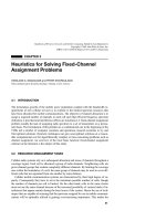
Figure 4.1: Contour plots of interference rejection achieved using a four element antenna array with
an inter-element spacing of X/2 using SMI beamforming with a reference signal length
of 16 bits. The angles of arrival of the signals from the desired source and the interfering
source were sweptover the range, -90 degrees to +90 degrees.
4.2.2 Using Probability Density Functions
Due to the inherent complexities of performing large-scale network simulations, whilst invoking the required beamforming operations, we conducted an investigation into the probability distribution of the interference rejection ratio achieved by an adaptive antenna array.
For our initial studies a two element antenna array with the elements located A/2 apart was
considered, with one desired source and one interfering source. Therefore, the average interference rejection achieved in decibels, for a given source-direction and power as well as
interferer-direction and power could be determined. Unfortunately, as it can be seen from
Figure 4.1 (a), the achievable interference rejection was not based upon a linear relationship
between the twoangles of arrival. Furthermore, Figure 4.l(b) illustrates that the interference
rejection achieved was also related to the power, or the Signal-to-Noise Ratio (SNR), of the
undesired interference source, which was 3 dB or 12 dB. As it was found in Section 4.2.1,
attempting to construct a model or probability density function to cater for these parameters
was not easily achievable. Rather than attempting to find the Probability Density Function
(PDF) relating the two angles of arrival and interference power to the interference rejection
achieved, a brief study was initiated for determining the PDF of the interference rejection
achieved with respect to the angular separation between the desired signal and interfering
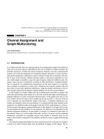
signal. Figure 4.2 shows the probability density function of interference rejection achieved
for one interference source and one desired source versus their angular separation. As this
figure shows, the distributionof the interferencerejection varies significantly, as the separation between the sources changes. As a consequence of the PDF's dependence on the angular
separation encountered, modelling the achievable interference rejection expressed in decibels
4.2. MODELLING ADAPTIVE
ARRAYS
ANTENNA
197
0.0 16
c
Separation
0.014
0 5'
0 10'
0
0.012
A 20'
X 40'
3
h 0.01
.*
Y
8 0.008
Q
h
5 0.006
.*
%
a"
0.004
0.002
0.0
0
10
20
30
40
Interference rejection, dB
50
l
t
60
Figure 4.2: The PDF of the interference rejection (dB) achieved for various angular separations of the
desired signal and the interfering signal. The angles of arrival of both signals were varied
over the range of -90 to +90 degrees and were of equal power. The antenna array consisted
of two elements separated by X/2.
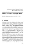
is an arduous task. Due to the complex natureof the PDF illustrated in Figure 4.2, an analysis
of a smaller rangeof angles of arrival was conducted, in order to construct a piecewisevalid
model. The results are displayed in Figures 4.3(a) and 4.3(b) for angle of arrival spreads of
f30" and *lo", respectively. While these PDFs appearto be considerably simplerthan that
in Figure 4.2, it was not possible to match the PDFs to any commonly known distributions.
Additionally, no information was available with regard to the correlation between successive interference rejection values. For these reasons, and due to the difficulties associated
with adding multipath, it was decided to cease work on constructing a suitable interference
rejection model and instead to implement an actual SMI beamformer within the simulation
program as described in the following section.
.8
4.2.3 Sample Matrix Inversion Beamforming
The processof defining asuitable model of an adaptive antenna array
was becoming increasingly complex, resulting in the decision to implement an SMI beamformer in the simulation
software. The SMI beamforming algorithm of Section 3.3.2.3 was chosen due to its inde-
CHAPTER 4. ADAPTIVE
ARRAYS
198
IN CELLULAR
NETWORKS
0.016
E
Separation
0.014
0
0 loo
0
.e
'j
E
0.012
A 20'
x 40'
z
,x 0.01
.e
0.008
Q
x
3 0.006
2
5 0.004
a
0.002
0.0
(a)
0.016
Angular s p r e a d = i 3 0 ° .
1
l
I
0
10
20
30
40
60
50
Interference rejection, dB
(b) Angular s p r e a d = f l O O
Figure 4.3: The PDF of the interference rejection achieved for the desired signal and the interfering
signal angular separations of 5, 10 and 20 degrees. The desired signal and the interfering
signal were of equal power. The antenna array consisted of two elements separated by X/2.
4.3. CHANNEL ALLOCATION TECHNIQUES
199
pendence from the received signal strengths, as well as due to its fast convergence with the
aid of fewdata samples andfor the sake of its good overall performance in terms of its interference rejection capability. The reference signal was chosen to be eight bits in length as a
compromise betweenthe quality of the sample correlation matrix, R, and the computational
complexity required. Since a cellular network is an interference limited system, the addition
of noise to the received signal vector was neglected. A result of this was that occasionally
the correlation matrix, R, was non-invertible, which wasremedied by diagonally augmenting
the matrix with a positive constant as it was suggested in [15,271,272]. The addition of
multipaths simply requiredthe direction of arrival, and the strength of the multipath rays at
the antenna array to be determined before adding these received signal vectors to the total
received signal vector of the antenna array. In both the line-of-sight and the multipath scenarios, the transmidreceive channelwas assumed to be frequency invariant, thus allowingthe
same antennapattern to be used in both the uplink andthe downlink.
4.3 ChannelAllocationTechniques
P.J. Cherriman, L. Hanzo'
Channel assignment is the process of allocating a finite number of channels to the various
base stations and mobile phones in the cellular network. In a system using fixed channel
assignment, the channels are assigned to different cells during the network planning stage,
and the assignment is rarely altered to reflect changes in traffic levels. A channelis assigned
to a mobile at the commencement of the call and the mobile communicates with its base
station on this channel until either the call terminates or the mobile leaves the current cell.
Dynamic channelallocation, however, assigns a channelthat best meets the channel selection
criteria, which may be the channel experiencingthe minimum interference level, depending
upon the cost function used.
With the growth in the number of subscribers to mobile telecommunications systems
worldwide and the expected introductionof multimedia services in handheld wireless terminals, a tremendous demandfor bandwidth hasarisen. Since bandwidthis scarce and becoming increasingly expensive,it must be utilized in an efficient manner.
The main limiting factor in radio spectrum reuse is co-channel interference. In reduced
cell-size micro/picocellular architectures, the frequency reuse distance is reduced, thereby
increasing the capacity and area spectral efficiency of the system. However, as the channel reuse distanceis reduced, the co-channel interference increases. CO-channel interference
caused by frequency reuse is the most severe limiting factor of the overall system capacity
of mobile radio systems. The
most important techniquefor reducing co-channelinterference
is power control, an issue, which will be discussed in detail in the context of adaptive modulation during our further discourse. Interference cancellation techniques [298] or adaptive
antennas [299-3011 can also be used to reduce co-channel interference. However, a simpler
and moreeffective technique used incurrent systems is employing sectorized antennas [302].
Although handoversare necessary in mobile radio systems, they often cause several problems, and they constitute the major cause of calls being forcibly terminated. As the cell size
is decreased, the average sojourn time or
cell-crossing time for a useris reduced. Thisresults
' This section isbased on [ 15 l ]
200
CHAPTERCELLULAR
4. NETWORKS
ADAPTIVE
ARRAYS
IN
in an increased number of handovers, requiring more rapid handover completion. In practice a seamless handover is not always possible exceptwhen soft-handovers [303] are used
in CDMA-based systems. Rapid and numerous handovers require a fast backbone network
between the base stations and the mobile switchingcenters, or they necessitate an increased
number of mobile switching centers. Clearly, the handover process is crucial with regard to
the perceived Gradeof Service (GOS), and a wide range
of different complexity techniques
have been proposed, for example, by Tekinay and Jabbari [304] and Pollini [305]for the
forthcoming future systems. The related issue of time-slot reassignment was investigated by
Bernhardt [306].
4.3.1
Overview of Channel Allocation
The purposeof channel allocation algorithms is to exploit the variability of the radio channel
propagation characteristics in order to allow increased efficiency radio spectrum utilisation,
while maintaining requiredsignal quality. The most commonly used signal quality measure
is the signal-to-interference ratio (SIR), also known as the carrier-to-interference ratio (CIR).
The signal quality measure that we have usedpreviously was the signal-to-interference+noise
ratio (SINR). The SINRis approximately equalto the signal-to-noise ratio (SNR) in a noiselimited environment and approximately equalto the SIR in an interference-limited environment.
The radio spectrum is dividedinto sets of noninterfering physicalradio channels, which
can be achieved using orthogonal timeor frequency slots, orthogonal user signature codes,
and so on. The channel allocation algorithm attempts to assign these physical channels to
mobiles requesting a channel, such
that the required signal quality constraints are met. There
are three main techniques for dividing the radio spectrum into radio channels. The first is
frequency division (FD), in which the radio spectrum is divided into several nonoverlapping
frequency bands. However, in practice the spectral spillage from one frequencyband to another causes adjacent channelinterference, which can be reduced by introducing frequency
guard bands.However, these guard bandswaste radio spectrum,and hence there is a compromise between adjacent channelinterference and frequency band-packingefficiency. Tighter
filtering can help reduce adjacent channel interference, allowing the guard bands to be reduced.
The second techniqueis time division (TD), in which the radio spectrum is divided into
disjunct timeperiods, which are usually termed time-slots. However, using straight-forward
rectangular windowingof the time-domain signal corresponds to convolving the signal spectrum with a frequency-domainsinc-function, resulting in Gibbs-oscillation. Hence, in practical systems a smooth time-domain ramp-up
and ramp-down function associatedwith a timedomain guard period is employed. Therefore,
there is a trade-off between complex synchronisation, time-domain guardperiods, and adjacent channelinterference.
The third technique for dividing the radio spectrum into channels is code division (CD).
Code division multiple access (CDMA)[3941,307] has been used in military applications,
in the IS-95 mobile radio system [308], and in the recently standardized Universal Mobile
Telecommunications System (UMTS)[307,309]. In code division, the physical channelsare
created by encoding different users with different user signature sequences.
Inmost systemsacombination of these techniques is used. Forexample, the PanEuropean GSM system [28] uses frequency division duplexing for up- and down-link trans-
NIQUES
ALLOCATION
4.3. CHANNEL
201
Channel Assignment Strategies
Fixed
Dynamic
I
Flexible
Dynamicchannels
Locally Distributed
Static borrowing
Simple borrowing
Hybrid
borrowlng
e.g., LP-DDCA,
LOLIA,
LOMIA
J
Figure 4.4: Family tree of channel allocation algorithms.
missions, while accommodating eight TDMA users per carrier. In this chapter, the term
“channel” typically implies a physical channel,constituted by a time-slot of a given carrier
frequency.
A widevariety of channel allocation algorithms have been suggestedfor mobile radio systems. The majorityof these techniques canbe classified into one of three main classes: fixed
channel allocation (FCA), dynamic channel allocation (DCA), and hybrid channel allocation (HCA). Hybrid channelallocation is constituted by a combinationof fixed and dynamic
channel allocation, which is designed to amalgamate the best features of both, in order to
achieve better performance or efficiency than I X A or FCA can provide. Several channel
allocation schemes and the associated trade-offs in terms of performance and complexityare
discussed in detail in the excellent overview papers of Katzela and Naghshineh [310] and
those by Jabbari and Tekinay et al. [31l, 3 121. Figure 4.4 portrays the family tree for the
main types of channel allocation algorithms, where the acronyms are introduced during our
further discourse. Zander [313] investigated the requirements and limitations of radio resource management in general for future wireless networks. Everitt [314] compared various
fixed and dynamic channel assignment techniques and
investigated the effect of handovers in
the context of CDMA-based systems.
4.3.1.1 FixedChannel Allocation
In fixed channel allocation (FCA), the available radio spectrum is divided into sets of frequencies. Oneor more of these sets is then assignedto each basestation on a semipermanent
basis. The minimum distance betweentwo base stations, they have been assigned the same
202
CHAPTER 4. ADAPTIVE ARRAYS IN CELLULAR
NETWORKS
set of frequencies is referred to as the frequency reuse distance. This distance is chosen
such that the co-channel interference is within acceptablelimits, when interferers are at least
the reuse distance away from each other. The assignment of frequency sets to base stations
is based on a predefined reuse pattern. The group of cells that contain one of each of the
frequency sets is referred to as the frequency reuse cluster. The grade of frequency reuse
is usually characterized in terms of the number of cells in the frequency reuse cluster. The
lower the number of cells in a reusecluster, the more bandwidth-efficientthe frequency reuse
pattern and the higher the so-called area spectral efficiency, since this implies partitioning the
available total bandwidth in a lower numberof frequency subsets used in the different cells,
thereby supporting moreusers across a givencell area. However, small reuse clusters exhibit
increased co-channelinterference, which has to be tolerated by the transceiver.
In FCA, the assignment of frequencies to cells is considered semipermanent. However,
the assignment can be modified in order to accommodate teletraffic demand changes. Although FCA schemes are very simple, modifying themto adapt to changing traffic conditions
or userdistributions can be problematic. Hence,FCA schemes have to be designed carefully,
in order to remain adaptable and scalable, as the number of mobile subscribers increases.
In this context, adaptability implies the ability to rearrange the network to provide increased
capacity in a particular area on a long- or short-term
basis, where scalability refers to the ability of easily increasing capacity across the whole network via tighter frequency reuse. For
example, Dahlinet al. [3 151 suggested a reusepattern structure for the GSM system that can
be scaled to meet increased capacity requirements, as the number of subscribers increases.
This is discussed in more detail in the overview paper by Madfors et al. [316]. Each measure
invoked, in order to further increase the network capacity, increases the system’s complexity and hence becomes expensive. Furthermore, such systems cannot be easily modified to
provide increased capacityin the specific area of a traffic hot-spot on a short-term
basis.
A commonly invoked reuse clustedpattern is the seven-cell reuse cluster, providing coverage over regular hexagonal shaped cells, which is shown in Figure 4.5. Each cell in the
seven-cell reuse cluster has six first-tier co-channel interfering cells at a distanceD , the reuse
distance. By exploiting the simple hexagonal geometry seen in Figure 4.5 it can be shown
that for the seven-cell cluster the reuse distance, D , is 4.58 times the cell radius T [ 1511. This
reuse pattern supports the same numberof channels at each cell site, and hence the same system capacity. Therefore, the teletraffic capacity is distributed uniformly across all the cells.
Since traffic distributions usually are not uniform in practice, such a system can leadto inefficiencies. For example, under nonuniform traffic loading, some cells may have no spare
capacity; hence, new calls in these cells are blocked. However, nearby cells may have spare
capacity.
Several studies have suggested techniques to find the optimal reuse pattern for particular traffic and users distributions, as exemplified by the work of Safak [317], on optimal
frequency reuse with interference. While such contributions are useful, a practical system
would need to modify the whole network configuration every timethe traffic or user distributions changedsignificantly. Therefore, suboptimalbut adaptable and scalable solutions are
more desirable for practical implementations. When the traffic distribution changes, an alternative technique to modifying the reuse pattern is referred to as channel borrowing,which is
the subject of the next section.
NIQUES
ALLOCATION
4.3. CHANNEL
203
.
Base
station
with
omnidirectional antenna
CO-channel cell
Frequency reuse cluster
Figure 4.5: A commonly employed frequency reuse pattern for fixed channel assignment (FCA) algorithms. The frequency spectrum divided in seven frequency sets, one set assigned to
each cell, yielding a seven-cell reuse cluster. Omnidirectional antennae were used, and the
shaded cells represent cells assigned the same frequency set.
4.3.1.1.1 Channel Borrowing In channel-borrowing schemes, a cell that has a call setup
request butno available channels (whichis termed an acceptor cell), can borrow free channels
from neighbouringcells referred to as donor cells in order to accommodate new calls, which
would otherwise have been blocked. A channel can be borrowed only if its use will not
interfere with existing ongoing calls. When a channel is borrowed, several cells are then
prohibited fromusing the borrowed channel because would
it
cause interference. The process
of prohibiting the use of borrowed channels is referred to as channel locking [318]. The
various channel-borrowing algorithms differ in the way the free channel is chosen from a
donor cell to be borrowed by an acceptor cell.
There are three main types of channel-borrowing algorithms: static, simple, and hybrid
borrowing; a good overview
of these algorithms canbe found in [3 10-3 121. Static borrowing
could be described as a fixed channel re-allocation strategy rather than channel borrowing.
In static borrowing, channelsare reassigned fromlightly loaded cells to heavily loaded cells,
which are at distances in excess of the reuse distance. This reassignment is semipermanent
and can be done based on measured or predicted changes in traffic. The other two types of
channel borrowing (simpleand hybrid) are different from static borrowing in that borrowed
channels are returnedwhen the call using the channels endsor is handed off to another base
station. Therefore, the simple and hybrid channel borrowing schemes use short-term borrowing in order to cope with traffic excesses.
Simple channel- borrowing schemes allow any of the channels in a donor cell to be lent
to an acceptor cell. Hybrid channel borrowing schemes split the channels assigned to each
204
CHAPTERCELLULAR
4. NETWORKS
ADAPTIVE
ARRAYS
IN
cell into two subsets. One subset of channels cannot be lent to other cells; hence, these are
referred to as standard or local channels. The other subset can be lent to other cells, and so
they are termed nonstandard or borrowable channels.
Simple borrowing [287,3 1 1,3191can reducenew call blocking, but it can cause increased
interference in other cells; it can also prevent handovers of future calls in these cells. Experiments have shown that simple channel-borrowing algorithms perform better than static fixed
channel allocation under light- and moderate traffic loads. However, at high traffic loads the
borrowing of channels leads to channel locking, which reduces the channel utilisation and
therefore results in an increase in new call blocking and in failed handovers. The various
simple channel-borrowing algorithms differ in terms of flexibility, complexity and their reduction of channel locking. Some algorithms [287,3 191 pick the channel to borrow, while
taking into account the
associated “cost” in terms of channel locking for each candidate channel. Other algorithms [3 191 invoke channel reassignment in order to reducechannel locking.
The innovative technique used by Jiang and Rappaport [3 l81 to reduce channel locking is to
limit the transmission power of borrowedchannels.
Hybrid channel borrowing [3 10,3111 is a hybrid of simple channel borrowing and static
fixed channel allocation. By dividing the channels at each base station into two subsets, and
only allowing channels of one of the subsets to be borrowed, the chance of channel locking
or failed handovers can be mitigated under high traffic loads. A range of algorithms is discussed in the literature, each having different objectives in terms of improving performance
in a particular area of operation. Some algorithms [320] have the ratio of channels in each
subset assigned a priori, while others dynamically adapt the sizeof the subsets based on traffic measurements or predictions [321]. The algorithm may also check whether the candidate
borrowed channel is free in the co-channel cells [322]. A common technique [319,323] is
to reassign calls using a borrowed channel to another borrowed channel in order to reduce
channel locking. A better policy is to reassign a call currently using a borrowed channel to
a local channel, thereby returning the borrowed channel to the donor cell. Another procedure [320,322] to reduce
channel locking is to estimate the direction of movement of the mobile in anattempt to reduce future channel
locking and interference. A simple technique [324]
is to subdivide cells into sectors and only allow borrowed channels to be used in particular
sectors of the acceptor cell,thereby reducing channel locking.
4.3.1.1.2 FlexibleChannelAllocation
Flexible channel allocation schemes [310,3 1 1,
3251 are similar to hybrid channel allocation schemes (which are described in Section 4.3. l .3)
in that they divide the available channels into fixed and dynamicallocation subsets. However,
flexible channel allocation is similar to a fixed channel allocation strategy, such as that used
in static channel borrowing. In flexible channel allocation, the fixed channel set is assigned
to cells in the same way as in fixed and hybrid channel allocation. The dynamic or flexible
channels can be assigned to cells depending on traffic measurements or predictions. The
difference between so-called hybrid and flexible channel allocation schemes is that in hybrid
channel allocation the dynamic channels are
assigned to cells only for the duration of the call.
In flexible channel allocation the dynamic channels are assigned to cells, when the blocking
probability in these cells becomes intolerable. Flexible channel allocation requires much
more centralized control than hybrid channel allocation.
4.3. CHANNEL ALLOCATION TECHNIQUES
205
4.3.1.2 DynamicChannel Allocation
Although fixed channel allocation schemes are common in most existing cellular radio systems, the cost of increasing their teletraffic capacity can become high. In theory, the use of
dynamic channel allocation allows the employment of all carrier frequencies in every cell,
thereby ensuring much higher capacity, provided the transceiver-specific interference constraints can be met. Therefore, it is feasible to design a mobile radio system, which configures itself to meet the required capacity demands as and when they arise. However, in
practice there are many complications, which make this simplistic view hard to implement in
practice. Dynamic channelallocation is used, for example, in the Digital European Cordless
Telephone (DECT) standard[257,258,326-3281. Law and Lopes [329] used the DECT system to compare the performance of two distributed DCA algorithms. However, DECT is a
low-capacity system, wherethe time-slot utilisation is expected to be comparatively low. For
low slot utilisation DCA is ideally suited. Dynamic channel allocation becomes more difficult to use in large-cell systems, which have higher channel utilisation. Salgado-Galicia et
al. [330] discussedthe practical problems that may beencountered in designing a DCA-based
mobile radio system.
Even though much research has been
carried out into channel allocation algorithms, particularly dynamic channel allocation, many unknowns remain. For example, the trade-offs
and range of achievable capacity gains are not clearly understood. Furthermore, it is not
known how to combine even two simple algorithmsin order to produce a hybridthat has the
best features of both. One reason that the issues of dynamic channel allocation are not well
understood is the computational complexity encountered in investigating such algorithms.
In addition, the algorithms have to be compared to others in a variety of scenarios. Furthermore, changing one algorithmic parameter
in order to improve the performance in one respect
usually has some effect on another aspectof the algorithm’s performance, dueto the parameters highly interrelated nature. This is particularly true, since experience showed that some
handover algorithmsare better suited for employment in certain dynamic channelallocation
algorithms [304]. Therefore
the various channelallocation algorithms have to becompared in
conjunction with a variety of handover algorithmsin order to ensure that the performance is
not degraded significantly by a partially incompatible handover algorithm. The
large number
of parameters and the associated high computational complexity of implementing channel
allocation algorithms complicate studyof the trade-offs of the various algorithms.
Again, in dynamic channelallocation, typically all channels canbe used at any base station as long as they satisfy the associated quality requirements. Channels are then allocated
from this pool as and when they are required. This solution provides maximum flexibility
and adaptability at the cost of higher system complexity. The various dynamic channel allocation algorithms have to balance allocating new channels to users against the potential
co-channel interference they could inflict upon users already in the system. Dynamic channel allocation is better suited to microcellular systems [331] becauseit can handle the more
nonuniform traffic distributions, the increased handoverrequests, and the more variable cochannel interference better than fixed channel allocation due to its higher flexibility. The
physical implementationof DCA is more complex than that ofFCA. However, withDCA the
complex andlabor-intensive task of frequency planningis no longerrequired.
The majority of DCA algorithms choose the channel to be used based on received signal quality measurements. This informationis then used to decide which channel to allocate
CHAPTER 4. ADAPTIVE
ARRAYS
206
IN CELLULAR
NETWORKS
or whether to allocate a channel at all. It is sometimes better not to allocate a channel if it
is likely to inflict severe interference on another user, forcibly terminating existing calls or
preventing the setup of other new calls. Ideally, the channel quality measurements should be
made at both the mobile and base station. If measurements are made only at the mobile or
only at the base station, the channel allocation is partially blind [288]. Channel allocation decisions that are based on blind channel measurements can in some circumstances cause severe
interference, leading to the possible termination of the new call as well as curtailing another
user’s call, who is using the same channel.If measurements are madeat both the mobile and
the base station, then the measurements need to be compared, requiring additional signaling,
which increases the call setup time. The call setup time is longer in DCA algorithms than in
FCA due to the time required to make measurements and to compare them. This can be a
problem, when, for example,
a handover is urgently required.
Probably the simplest dynamic channel allocation algorithm is to allocate the least interfered channel available to users requesting a channel. By measuring the received power
within unused channels, effectively the noise plus interference on that channel can be measured. By allocating the least interfered channel, the new channel is not likely to encounter
interference, and, due to semireciprocity, it is not likely to cause too much interference to
channels already allocated. This works well for lightly loaded systems. However, this algorithm’s performance is seriously impaired in high-load scenarios, where FCA would work
better. However, the above is a very simple dynamic channel allocation algorithm. In Sections 4.3.4 and 4.4 we will demonstrate that it is possible to achieve a better performance and
efficiency than that of FCA even at high traffic loads, when using certain channel allocation
algorithms. For these reasons, some channelallocation algorithms use a combination of FCA
and DCA to achieve better performance than simple DCA, and better reuse efficiency than
FCA. These algorithms areclassified as hybrid channel allocation (HCA) algorithms.
The differencebetween the various dynamic channelallocation algorithms is, essentially,
how the allocated channel is chosen. All the algorithms assign a so-called cost to allocating
each of the possible candidate channels, and the one with the lowest cost is allocated. The
difference between the algorithms is how the “cost” is calculated using the cost function. The
cost function can becalculated on the basis of one or moreof the following aspects: future
call blocking probability; usage frequency of the channel; distance to where the channel is
already being used, that is, the actual reuse distance; channel occupancy distribution; radio
signal quality measurements; and so on. Some algorithms may give better performance than
others, but only in certain conditions. Most DCA algorithms’ objectives can be classified into
two types, where most of themattempt to reduceinterference, while others try to maximizee
channel utilisation in order to achieve spectral compactness.
There are three main types of DCA algorithms, namely:
0
Centrally controlled algorithms
0
Distributed algorithms
0
Locally distributed algorithms (hybrid)
4.3.1.2.1 CentrallyControlled DCA Algorithms Centrally controlled DCA algorithms
are also often referred to as centrally located or centralized DCA algorithms. These algorithms use interference measurements that are madeby the mobiles and base stations that are
4.3. CHANNEL
TECHNIQUES
ALLOCATION
207
then passed to a central controller, which in most cases would be a mobile switchingcenter.
The algorithm that determines the channel allocation is located at the central controller, and
it decides on the allocation of channels basedon the interference measurements providedby
all the base stations and mobiles under itscontrol. These algorithms providevery good performance even at high traffic loads. However, they are complex to implement and require a
fast backbone network betweenthe base stations and the central controller. The central controller can become a “bottleneck”and increase the call setup time, which may be critical for
“emergency” handovers.
Centralized algorithms[320,322,332-3341 have been researchedactively for over twenty
years. One of the simplest is referred to as the First Available (FA) [332,335] algorithm,
which allocates the first channel found that is not reused within a given preset reuse distance. The Locally Optimized Dynamic Assignment (LODA) [320,322] algorithm bases
its allocation decisions on the future blocking probability in the vicinity of the cell. Some
algorithms exploit the amount of channel usageto make allocation decisions. The RING algorithm [3 10,3341,
for example, allocates the most often used channel within the cells, which
are approximately at the reuse distance, and the terminology RING is justified by the fact that
these cells effectively form a ring. There are also several algorithms, which attempt to optimize the reuse distance constraint. The Mean Square (MSQ) algorithm [335] attempts to
minimize the mean square distance betweencells using the same channel while maintaining
the required signal quality. The Nearest Neighbour (NN) and Nearest Neighbour plus One
(NN+1) algorithms [332,335] pick a channelused by the nearest cell, which is at least at a
protection distance amounting to the reuse distance (or reuse distance plus one cell radius
for NN+1). Other algorithms [334] use channel reassignments
to maintain the reuse distance
constraint. Recall againthat these algorithms were summarizedin Figure 4.4.
4.3.1.2.2 Distributed DCA Algorithms In contrast to centrally controlled algorithms,
distributed algorithms are the least complex DCA techniques, in which the same algorithmis
used byeach mobileor base station in order to determine the best channel for setting up a call.
Each mobile and/or basestation makes channelallocation decisions independentlyusing the
same algorithm-hence the name distributed algorithms. The algorithmic decisions
are usually based on the interference measurements made by the mobile or the base station. These
algorithms are easy to implement, and they perform well for low-slot occupancy systems.
However, in high-load systemstheir performance is degraded.Distributed algorithms require
less signaling than centralized algorithms. However, the allocation is generally suboptimal
owing to their locally based decisions. One real advantage of distributed algorithms is that
base stations can easily be added, moved, orremoved because the system automaticallyreorganizes and reconfigures itself. However, the cost of this flexibility is that the local decision
making generallyleads to a suboptimal channel
allocation solution and to a higherprobability
of interference in neighbouring cells. Furthermore, generallydistributed algorithms are based
on signal strength measurements and estimates of interference. However, these interference
estimates can sometimesbe poor, which can leadto bad channel allocation decisions. When
a new allocation is made,the co-channel interference it inflicts may lead to an ongoingcall to
experience low-service quality, often termed a service interruption. If a service interruption
leads to the ongoing call being terminated prematurely, this is referred to deadlock [310].
Successive service interruptions are termed as instability. A further problem with distributed
algorithms isthat the same channel canbe allocated at the same timeto two or more different
208
CHAPTERCELLULAR
4.NETWORKS
ADAPTIVE
ARRAYS
IN
users in adjacent cells. However, when the mobiles attempt to use the channel, they may
find the quality unacceptably low. Therefore, distributed algorithms have to beable to check
the quality of an allocation, before it is made permanent,which increases the call setup time
further.
Chuang et al. [290] investigated the performance of several distributed DCA algorithms,
arguing that under certain conditions these techniques can convergeto a local minimum of
the total interference averaged overthe network. Grandhiet al. [336] and Chuanget al. [289]
also evaluated the performance of combining dynamic channelallocation with transmission
power control.
Examples of distributed algorithms are the Sequential Channel Search (SCS) and the
least interference algorithm (LIA). The SCS algorithm [337] searches
the available channels
in a predetermined order, picking the first channel found, which meets the interference constraints. The LIA algorithm, alluded to earlier, picks the channel with the lowest measured
interference that is available. One of the most complex distributed algorithms is the Channel
segregation technique[338], which is a fully distributed, autonomous, self-organising assignment scheme. Each cell maintains a measureof the relative frequency of channel usage for
each channel. This probability-based measure ismodified every time an attempt to access a
specific channel is made. The channel assigned to the new call is the one with the highest
probability of being or havingbeen idle. The algorithm has beenshown to reduce blocking
and adapt to traffic changes. Althoughthe channel allocation may rapidly convergeto a nearoptimal solution, it may take a long timeto reach a globally optimal solution. As before, for
the family tree of these techniques, pleaserefer to Figure 4.4.
4.3.1.2.3 Locally distributed DCA algorithms The third andfinal class of DCA algorithms are the locally distributed algorithms, which constitute a hybrid of distributed and
centralized algorithms. These algorithms provide the greatest number of performance benefits of the centralized algorithms at a much lower complexity. Examples of locally distributed DCA algorithms are those proposedby Delli Priscoli et al. [293,294] as an evolution
of the Pan-European GSM system [28]. Locally distributed DCA algorithms use information from nearby base stations to augment their local channel quality information in order to
make a more informed channel
allocation decision. Most of the locally distributed algorithms
maintain an Augmented Channel Occupancy (ACO) matrix [291]. This matrix contains the
channel occupancyfor the local and surroundingbase stations from which information is received. After every channel allocation, the information to update the ACO matrices is sent
to the nearby base stations. This signaling requires a fast backbone network,but it is far less
complex thanthe signaling required for the centralized algorithms.
The Local Packing Dynamic Distributed Channel Assignment (LP-DDCA) algorithm,
proposed in [291], maintains an ACO matrix for every base station for all surrounding cells
within the co-channel interference distance or reuse distance from the base station. The
LP-DDCA algorithm assigns the first channel available that is not used by the surrounding
base stations, whose information is contained in the ACO matrix. There are several algorithms similar to this one, including thoseby Del Re et al. [339], and the Locally Optimized
Leasmost Interference Algorithms (LOLIALOMIA) that we will use in Section 4.3.3.3 in
the context of our performance comparisons.
An overview of the main differences between fixed and dynamic channel allocation is
shown in Table 4.1; exploration of itsdetailed contents is left to the reader. However, thistable
4.3. CHANNEL
TECHNIQUES
ALLOCATION
209
-
Fixed Channel Allocation (FCA)
Dynamic Channel Allocation (DCA)
0 Better under heavy
traffic loads
Better under lighvmoderate
traffic loads 0 Low call setup delay
0 Moderate to high call setup delay
0 Suited to large-cell environment
0 Suited to microcellular environment
0 Low flexibility in channel assignment
Highly flexible channel assignment
0 Sensitive to time and spatial changes in
Insensitive to time and spatial changes
traffic load
in traffic load
0 Low computational complexity
0 High computational complexity
0 Labor-intensive and complex frequency 0 No frequency planning required
planning
0 Radio equipment only covers channels
Radio equipmentmay have to cover all
assigned to cell
r)ossible channels available
0 Low
signaling
load
High signaling load
0 Centralized control
11 0 Control
dependent
on
the specific
schemefrom centralized to fully distributed
0 Medium to high implementational com0 Low implementational complexity
plexity
0 Increasing system capacityis expensive
0 Simple and quick
to increase system caand time-consuming
pacity
~
(1
Table 4.1: FCA and DCA Features
does not showthe increase in spectral efficiency andchannel utilisation that becomes possible
with dynamic schemes,as will be demonstrated during our performance comparisons.
4.3.1.3 HybridChannel Allocation
Hybrid channel allocation schemes constitute a compromise between fixed and dynamic
channel allocation schemes. They have been suggested in order to combine the benefits
of DCA at low and medium traffic loads with the more stable performance of FCA at high
traffic loads. Furthermore, hybrid schemeshave been proposed as possible extensions to the
fixed channel allocation used in second-generation mobile radio systems. In hybrid channel allocation schemes, the channels are divided into fixed and dynamic subsets. The fixed
channels are assigned to the cells, as would be done for fixed channel allocation, and they
are the preferred choice for channelallocation. When a cell exhausts all its fixed channels, it
attempts to allocate a dynamically assigned channel fromthe central pool of channels. The
algorithm used to pick the dynamically allocated channel dependson the hybrid scheme,but
it can be any arbitrary DCA algorithm. The ratio of fixed and dynamic channels could be
fixed [340] or varied dynamically, dependingon the traffic load. At high loads, best performance is achieved, when the hybrid scheme behaveslike FCA, by having none or alimited
number of dynamically allocated channels [340,341]. Some hybrid channelallocation algorithms reallocate fixed channels, which become free to calls using dynamic channelsin order
to free up the dynamic channels. This techniqueis known as channel reordering [334].
210
CHAPTERCELLULAR
4. NETWORKS
ADAPTIVE
ARRAYS
IN
4.3.1.4 The Effect of Handovers
A handoveror handoff event occurs
when the quality of the channel beingused degrades, and
hence the call is switched to a newly allocated channel. If the new channel belongs to the
same base station, then this is called an intra-cell handover. If the new channel belongs to a
different base station, it is referred to as an inter-cell handover. Generallyintra-cell handovers
occur when the channel quality degrades due to interference or when the channel allocation
algorithm decidesthat a channelreallocation will help increase the system’s performance and
capacity. Inter-cell handovers occur mainly becausethe mobile moves outside the cell area;
hence, the signal strength degrades, requiringa handover to a nearer basestation.
Handovers have a substantial effect on the performance of channel allocation algorithms.
At high traffic loads, the majority of forced call terminations are due to the lack of channels
available for handover rather than to interference. This can be a particular problem in microcellular systems, where the rate of handovers is significantly higher than that in normal
cellular systems.
There are several known solutions to reduce the performance penalty caused by handovers. One of the simplest solutions is to reserve some channels exclusively
for handovers,
commonly referred to as cutoff priority 1304,342,3431or guard channel13441schemes. However, this solution reduces the maximum amount of carried traffic or system capacity and
hence yields increased new call blocking. The guard or handover channels not
do need to be
permanently assignedto cells; they are invoked from an “emergency pool.”
Algorithms that give higherpriority to requests for handovers than to new calls are called
Handover prioritisation schemes. Guard channel schemes are therefore a type of handover
prioritisation arrangement. Another type
of handover prioritisation is constituted by handover
queuing schemes[3 10,3l 1,342,3431. Normally,when anallocation request for handoff is rejected, the call is forcibly terminated. By allowing handoverallocation requests to be queued
temporarily, the forced terminationprobability can be reduced. The simplest handover queuing schemes use aFirst-In First-Out (FIFO) queuing regime[343]. Tekinay et al. 13041have
suggested a nonpreemptivepriority handover queuing schemein which handover requests in
the queuethat are the most urgent onesare served first.
A further alternative to help reducethe probability of handover failure is to allow allocation requests for new calls to be queued [344]. New call allocation requests can be queued
more readily than handovers becausethey are less sensitive to delay. Handover queuingreduces the forced terminationprobability owing to handover failures but increases the new call
blocking probability. New call queuing reduces the new call blocking probability and also
increases the carried teletraffic. This is because the new calls are not immediately blocked
but queued, and in most cases they receive an allocation later.
4.3.1.5 The Effect of Transmission Power Control
Transmission power control is an effective way of reducing co-channel interference while
also reducing the power consumption of the mobile handset. Jointly optimising transmission powercontrol with the channel allocation decisions is promising in terms of increasing
spectral efficiency. However, little research has been done into this area, apart from a contribution by Chuang and Sollenberger [289] showing the potential benefits. Transmission
power control, like channel allocation, can be implemented in a centralized 1345,3461 or
distributed [347] manner.
NIQUES
ALLOCATION
4.3. CHANNEL
211
An alternative fixed channel allocation strategy, referred to as Reuse partitioning [310],
relies on transmission powercontrol. In reuse partitioning, a cell is divided into two or more
concentric subcells or zones. If a channel is used in the inner zone with transmission power
control, the interference is reduced due to the reduced transmission power. Therefore, the
interference from channels used in the inner zones is less than that by those channels, used
in the outer zones. Channels used in the inner zones can thus be reused at much shorter
distances than thoseutilized in the outer zones.
By combining transmissionpower control with dynamic channelallocation, the additional
performance gainsof reuse partitioning can be achieved. Using reusepartitioning with DCA
is far simpler to implement than usingFCA, since the system isself-configuring and doesnot
require network reusepattern planning.
4.3.2 Simulation of the Channel Allocation Algorithms
In this section, we highlight how we simulated the various channelallocation algorithms we
investigated. Section 4.3.2.1 describes the simulation program, “Netsim,” which was developed to simulate the performance of the channel allocation algorithms. The channel allocation algorithms that we simulated are described in detail in Section 4.3.3. In Section 4.3.3.4,
we describe the performance metricswe have used to compare the performance of the channel allocation algorithms. Finally, in Section 4.3.3.5, we describe the model used to generate
the nonuniform traffic distributions we used inour simulations.
4.3.2.1 The Mobile Radio Network Simulator, “Netsim”
In order to characterize the performance of the various channel allocation algorithms, we
simulated a mobile radio network. The simulator program we developed is referred to as
Netsim. The simulated base
stations can be placed in a regular pattern or at arbitrary positions
within the simulation area. Mobiles are distributed randomly acrossthe simulation area. Each
mobile can havedifferent characteristics, such as a particular mobility modelor velocity.
A screenshot from the simulator is shown in Figure 4.6. The figure shows a forty-ninebase station simulation, where the cell areas are represented by circles. The mobiles are
shown assmall squares, and when they become active, they change color on
the video screen.
The connection betweenan active mobile and a base station is represented by a line linking
the base station and the mobile. The simulatorhas the following features:
New Call Queuing Channel allocation requests for new calls are queued if they cannot immediately be served [344]. The new call request is blocked if its request cannot be
served within a preset timeout period, referred to as the Maximum new-call queue
time.
Handover Prioritisation Channel allocation requests for handovers are given priority over
new calls, supporting HandoverPrioritisation 13101.
Handover Urgency PrioritisationChannel allocation requests for handoversare processed
by each base station, so that the more urgent handoversare served first [304].
Handover HysteresisA call will not be handed over to another base station or channel unless the new channel has asignal quality better than the current channel by at least the
212
CHAPTERCELLULAR
4.NETWORKS
ADAPTIVE
ARRAYS
IN
Figure 4.6: Screenshot of the Netsim program, showing 100 users in a 49-cell simulation. Each base
station is located at the center of each cell, and the large circles represent the radius of the
cell area. The connection between an active mobile and a base station is represented by a
line.
preset handover hysteresis level. The only exception is when the currentchannel quality is below the signal qualitylevel required to maintain the call and the new channel is
above this quality level, but the differencebetween the quality of the new and current
channel is less than the hysteresis threshold.
Channel Models The simulator models each propagation channel using one of several pathloss models and a shadow fading model. The shadow fading model can be turned off if
necessary.
Call Generation Model Each mobile’s activity is described by how much of the time the
mobile is active (i.e., making a call). The activity of each mobile is controlledby two
parameters, average call duration and average intercall time. The average call duration
is the long-term mean of the length of all the calls made by the mobile. The duration of
all thecalls made by the mobile is Poisson-distributed [289,348]. The average intercall