Tài liệu Sổ tay của các mạng không dây và điện toán di động P7 pdf
Bạn đang xem bản rút gọn của tài liệu. Xem và tải ngay bản đầy đủ của tài liệu tại đây (317.41 KB, 26 trang )
CHAPTER 7
Traffic Integration in Personal, Local, and
Geographical Wireless Networks
RAFFAELE BRUNO, MARCO CONTI, and ENRICO GREGORI
CNR, Istituto CNUCE, Pisa, Italy
7.1 INTRODUCTION
Currently, users identify wireless networks with first- and second-generation cellular tele-
phony networks. Although voice and short messaging have driven the success of these net-
works so far, data and more sophisticated applications are emerging as the future driving
forces for the extensive deployment of new wireless technologies.
In this chapter, we will consider future wireless technologies that will provide support
to different types of traffic including legacy voice applications, Internet data traffic, and
sophisticated multimedia applications.
In the near future, wireless technologies will span from broadband wide-area technolo-
gies (such as satellite-based networks and cellular networks) to local and personal area
networks. In this chapter, for each class of network, we will present the emerging wireless
technologies for supporting service integration. Our overview will start by analyzing the
Bluetooth technology [30] that is the de facto standard for wireless personal area networks
(WPANs), i.e., networks that connect devices placed inside a circle with radius of 10 me-
ters. Two main standards exist for wireless local area networks (WLANs): IEEE 802.11
[21] and HiperLAN [15]. In this chapter we focus on the IEEE 802.11 technology, as it is
the technology currently available on the market. After a brief description of the IEEE
802.11 architecture, we will focus on the mechanisms that have been specifically designed
to support delay-sensitive traffic.
For wireless wide area networks, we will focus on the technology for third-generation
mobile radio networks. Two standards are emerging worldwide for this technology: the
Universal Mobile Telecommunication System (UMTS) of the European Telecommunica-
tion Standard Institute (ETSI), and the International and Mobile Telecommunications-
2000 (IMT-2000) of the International Telecommunication Union (ITU). The differences
between these two standards are not relevant for the discussion in this chapter. Whenever
necessary, we will use UMTS as the reference technology [1, 32].
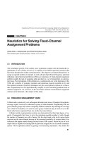
All the network technologies analyzed in this chapter operate according to the infra-
structure-based approach (see Figure 7.1). An infrastructure-based architecture imposes
the existence of a centralized controller for each cell, which takes different names depend-
145
Handbook of Wireless Networks and Mobile Computing, Edited by Ivan Stojmenovic´
Copyright © 2002 John Wiley & Sons, Inc.
ISBNs: 0-471-41902-8 (Paper); 0-471-22456-1 (Electronic)
ing on the technology: master, access point, base station, etc. The cell identifies the area
covered by the centralized controller, i.e., the area inside which a mobile terminal can di-
rectly communicate with the centralized controller. The cell size, as said before, depends
on the technology, e.g., from 10 meters in Bluetooth up to kilometers in UMTS. Further-
more, inside UMTS, cells of different sizes can be used to accommodate different classes
of users.
The centralized controller is connected to the wired network so as to have both intercell
communication and access to other networks such as Internet.
WPANs and WLANs may also operate in the ad hoc mode [29]. An ad hoc network is a
set of mobile terminals within the range of each other that dynamically configure them-
selves to set up a temporary network (see Figure 7.1). In this configuration, no fixed con-
troller is required, but a controller is dynamically elected among all the stations participat-
ing in the communication.
Both in the infrastructure-based and ad hoc modes, the centralized controller is in
charge to manage the radio resources of its cell. To achieve this, the following functionali-
ties are implemented in all the network technologies we analyze: a medium access control
mechanism, a scheduling algorithm, and a signaling channel for the communications from
the centralized controller to the mobile terminals (downlink signaling channel).
The medium access control mechanism is required for managing the communications
from the mobile terminals to the controller, and it is used by the mobile terminals for re-
questing transmission resources. In all technologies, this mechanism is used when a mo-
bile terminal needs to start a communication and hence does not yet have any transmission
resources allocated to it. In this case, the mobile terminal transmits on a channel that is
shared among all the terminals in the cell. Protocols belonging to the random access class
are typically used to implement the medium access control mechanisms [18]. Once the
146
TRAFFIC INTEGRATION IN PERSONAL, LOCAL, AND GEOGRAPHICAL WIRELESS NETWORKS
BSS 1
BSS 3
wired network
Infrastructure Mode
Ad hoc Mode
Figure 7.1 Infrastructure-based and ad hoc networks.
centralized controller receives the mobile terminal requests, it assigns the transmission re-
sources according to the rules defined by its scheduling algorithm. Finally, the assigned
resources are communicated to the terminals through the downlink signaling channel.
As the emphasis of this chapter is on the integration of different types of traffic, we
will primarily focus on the medium access control mechanisms, the scheduling algo-
rithms, and the downlink signaling channels adopted by these technologies.
7.2 A TECHNOLOGY FOR WPAN: BLUETOOTH
Bluetooth wireless technology is a de facto standard for low-cost, short-range, radio links
between mobile PCs, mobile phones, and other portable devices. The Bluetooth specifica-
tions are released by the Bluetooth Special Interest Group (SIG), an industry group con-
sisting of industrial leaders in the telecommunications, computing, and networking [11].
In addition, the IEEE 802.15 Working Group for Wireless Personal Area Networks has
started a project to publish and approve a standard derived from the Bluetooth specifica-
tion [20].
The Bluetooth system operates in the 2.4 GHz industrial, scientific, and medicine
(ISM) band. It is based on a low-cost, short-range radio link integrated into a microchip,
enabling protected ad hoc connections for wireless communication of voice and data in
stationary and mobile environments. It enables use of mobile data in different ways for
different applications. Due to its low-cost target, it can be envisaged that Bluetooth mi-
crochips will be embedded in all consumer electronic devices.
The characteristics of the Bluetooth technology offer wide room for innovative solu-
tions and applications that could bring radical changes to everyday life. Let us imagine a
PDA (with a Bluetooth microchip) that automatically synchronizes with all the electronic
devices in its 10 meter range when you arrive at your home. Your PDA can, for example,
automatically unlock the door, turn on the house lights while you are getting in, and adjust
the heat or air conditioning to your preset preferences. But not only the home can become
a more comfortable environment when the access to information is fast and easy. Let us
imagine arriving at the airport and finding a long queue at the check-in desk for seat as-
signment. You can avoid the queue using a hand-held device to present an electronic ticket
and automatically select your seat.
7.2.1 The Bluetooth Network
From a logical standpoint, Bluetooth belongs to the contention-free, token-based multiac-
cess networks [18]. In a Bluetooth network, one station has the role of master and all oth-
er Bluetooth stations are slaves. The master decides which slave is the one to have access
to the channel. The units that share the same channel (i.e., are synchronized to the same
master) form a piconet, the fundamental building block of a Bluetooth network. A piconet
has a gross bit rate of 1 Mbps that represents the channel capacity before considering the
overhead introduced by the adopted protocols and polling scheme. A piconet contains a
master station and up to seven active (i.e., participating in data exchange) slaves simulta-
neously. Independent piconets that have overlapping coverage areas may form a scatternet.
7.2 A TECHNOLOGY FOR WPAN: BLUETOOTH
147
A scatternet exists when a unit is active in more than one piconet at the same time (a unit
can be master in only one piconet). A slave may communicate with the different piconets
it belongs to only in a time-multiplexing mode. This means that, for any time instant, a
station can only transmit on the single piconet to which its clock is synchronized at that
time. To transmit on another piconet, it has to change the synchronization parameters.
More details on construction procedures for piconets and scatternets can be found in
Chapter 27 of this handbook.
7.2.2 The Bluetooth Architecture
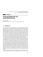
The complete protocol stack contains a Bluetooth core of Bluetooth-specific protocols:
Bluetooth radio, baseband, link manager protocol (LMP), logical link control and adapta-
tion protocol (L2CAP), service discovery protocol (SDP) as shown in Figure 7.2. In addi-
tion, examples of higher-layer non-Bluetooth-specific protocols are also shown in the fig-
ure; these can be implemented on top of the Bluetooth technology.
Bluetooth radio provides the physical links among Bluetooth devices and the baseband
layer provides a transport service of packets on the physical links. In the next subsections
these layers will be presented in detail.
The LMP protocol is responsible for the set-up and management of physical links. The
management of physical links consists of several activities: putting a slave in a particular
operating state (i.e., sniff, hold, or park modes [30]), monitoring the status of the physical
channel, and assuring a prefixed quality of service (e.g., LMP defines transmission power,
maximum poll interval, etc.). LMP also implements security capabilities at link level.
The radio, baseband, and LMP may be implemented in the Bluetooth device. The de-
vice will be attached to a host, thus providing that host with Bluetooth wireless communi-
148
TRAFFIC INTEGRATION IN PERSONAL, LOCAL, AND GEOGRAPHICAL WIRELESS NETWORKS
Bluetooth radio
Baseband
LMP
L2CAP
Audio
RFCOMM
PPP
IP
UDP
OBEX WAP
AT
Commands
TCS BIN
SDP
vCard WAE
TCP
Host
Controller
Interface
Figure 7.2 Bluetooth protocol stack.
cation. L2CAP layer and the other high-layer protocols are in the host. The host controller
interface is a standard interface that enables high-layer protocols to access the services
provided by the Bluetooth device.
The L2CAP services are used only for data transmissions. The main features supported
by L2CAP are: protocol multiplexing (the L2CAP uses a protocol-type field to distinguish
between upper-layer protocols) and segmentation and reassembly. The latter feature is re-
quired because the baseband packet size is smaller than the usual size of packets used by
higher-layer protocols.
In legacy LANs, users locate services such as file server, print server, and name server
by some static configuration. The configuration is usually established and maintained by a
system administrator who manually configures the client devices. For dynamic ad hoc net-
works, this static configuration is not adequate. The SDP protocol is used to find the type
of services that are available in the network.
Finally, RFCOMM is a serial line emulation protocol, i.e., a cable replacement proto-
col. It emulates RS-232 control and data signals over Bluetooth baseband, providing trans-
port capabilities for upper-level services that use serial lines as their transport mechanism.
7.2.3 The Bluetooth Device
A Bluetooth unit consists of a radio unit operating in the 2.4 GHz band. In this band, 79
different radio frequency (RF) channels that are spaced 1 MHz apart are defined. The ra-
dio layer utilizes the frequency hopping spread spectrum (FHSS) as its transmission tech-
nique. The hopping sequence is a pseudorandom sequence of 79 hop length, and it is
unique for each piconet. It is enabled by exploiting the actual value of the master clock
and its unique Bluetooth device address, a 48 bit address compliant with the IEEE 802
standard addressing scheme [30]. The FHSS system has been chosen to reduce the inter-
ference of nearby systems operating in the same frequency range (for example, IEEE
802.11 WLAN) and make the link robust [12, 17]. The nominal rate of hopping between
two consecutive RF is 1600 hop/sec.
A time division duplex (TDD) scheme of transmission is adopted. The channel is divid-
ed into time slots, each 625 s in length, and each slot corresponds to a different RF hop
frequency. The time slots are numbered according to the Bluetooth clock of the master.
The master has to begin its transmissions in even-numbered time slots. Odd-numbered
time slots are reserved for the beginning of the slaves’ transmissions.
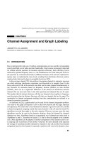
The transmission of a packet nominally covers a single slot, but it may last up to five
consecutive time slots (see Figure 7.3). For multislot packets, the RF hop frequency to be
used for the entire packet is the RF hop frequency assigned to the time slot in which the
transmission has begun. The RF change reduces the interference from signals coming
from other radio modules.
There are two types of physical links that can be established between Bluetooth de-
vices: a synchronous connection-oriented (SCO) link, and an asynchronous connection-
less (ACL) link. The first type of physical link is a point-to-point, symmetric connection
between the master and a specific slave. It is used to deliver delay-sensitive traffic, mainly
voice. In fact, the SCO link rate is 64 Kbit/s and it is settled by reserving a couple of con-
secutive slots for master-to-slave transmission and immediate slave-to-master response.
7.2 A TECHNOLOGY FOR WPAN: BLUETOOTH
149
The SCO link can be considered a circuit-switched connection between the master and the
slave. The second kind of physical link, ACL, is a connection between the master and all
slaves participating in the piconet. It can be considered a packet-switched connection be-
tween the Bluetooth devices and can support the reliable delivery of data: a fast automatic
repeat request (ARQ) scheme is adopted to assure data integrity. An ACL channel sup-
ports point-to-multipoint transmissions from the master to the slaves.
As stated above, channel access is managed according to a polling scheme. The master
decides which slave is the only one to have access to the channel by sending it a packet. The
master packet may contain data or can simply be a polling packet. When the slave receives
a packet from the master, it is authorized to transmit in the next time slot. For SCO links, the
master periodically polls the corresponding slave. Polling is asynchronous for ACL links.
Figure 7.4 presents a possible pattern of transmissions in a piconet with a master and two
slaves. Slave 1 has both a SCO (packets filled with diagonal lines) and an ACL (packets
filled with horizontal lines) link with the master, whereas Slave 2 has an ACL link only
(packets filled with vertical lines). In this example, the SCO link is periodically polled by
the master every six slots, whereas ACL links are polled asynchronously. Furthermore, the
size of the packets on an ACL link is constrained by the presence of SCO links. For exam-
ple, in Figure 7.4 the master sends a multislot packet to Slave 2, which, in turn, can reply
with a single-slot packet only, because the successive slots are reserved for the SCO link.
As stated above, a piconet has a gross bit rate of 1 Mbps. The polling scheme and the
protocols control information, obviously reducing the amount of user data that can be de-
livered by a piconet. We analyze the limiting performance of a piconet below. This analy-
sis is performed by assuming a single master–slave link in which both stations operate un-
der asymptotic conditions, i.e., the stations always have a packet ready for transmission.
The results of this analysis are summarized in Tables 7.1 and 7.2 for SCO and ACL links,
respectively. To enhance the reliable delivery of the packets, forward error correction
(FEC) and cyclic redundancy check (CRC) algorithms may be used. The possible pres-
ence of FEC, CRC, and multislot transmission results in different payload lengths, as sum-
marized in the tables.
150
TRAFFIC INTEGRATION IN PERSONAL, LOCAL, AND GEOGRAPHICAL WIRELESS NETWORKS
f(k)
f(k+1)
f(k+2) f(k+3)
f(k+4) f(k+5)
f(k+6)
f(k)
f(k)
f(k+3)
f(k+4)
f(k+5)
f(k+6)
f(k+6)
f(k+5)
625 µs
366 µs
Figure 7.3 Physical channel structure with multislot packets.
The SCO packets (see Table 7.1), denoted by HVy, are never retransmitted and the pay-
load is not protected by a CRC. The y indicates the FEC level and it also identifies how
many SCO connections may be concurrently active in a piconet. In addition to the three
pure SCO packets, a DV packet is defined that can also carry asynchronous data but is
still recognized on SCO links. In the Table 7.1, the items followed by “D” relate to the data
field only. The ACL packets (see Table 7.2) are of two different groups, one denoted DMx
(medium-speed data) and the other one denoted DHx (high-speed data). The former has a
payload encoded with a 2/3 FEC and the latter has no FEC encoding. The subscript x
7.2 A TECHNOLOGY FOR WPAN: BLUETOOTH
151
SCO SCO SCO SCOACL ACL ACL
MASTER
SLAVE 1
SLAVE 2
Figure 7.4 An example of transmissions in a Bluetooth piconet.
TABLE 7.1 SCO packets
User payload Symmetric maximum
Type (bytes) FEC CRC rate (kbps)
HV1 10 1/3 no 64.0
HV2 20 2/3 no 64.0
HV3 30 no no 64.0
DV 10 + (0–9)D 2/3 D yes D 64.0 + 57.6 D
TABLE 7.2 ACL packets
Asymmetric maximum
User Symmetric rate (kbps)
payload maximum rate
_____________________
Type (bytes) FEC CRC (kbps) Forward Reverse
DM1 0–17 2/3 yes 108.8 108.8 108.8
DM3 0–121 2/3 yes 258.1 387.2 54.4
DM5 0–224 2/3 yes 286.7 477.8 36.3
DH1 0–27 no yes 172.8 172.8 172.8
DH3 0–183 no yes 390.4 585.6 86.4
DH5 0–339 no yes 433.9 723.2 57.6
stands for the number of slots that are necessary to transmit the packet. All ACL packets
have a CRC field for checking the payload integrity. Tables 7.1 and 7.2 summarize SCO
and ACL packet characteristics, respectively. In addition, the tables report, assuming a pi-
conet with two only devices, the maximum aggregate piconet throughput for symmetric
and asymmetric communications. In the asymmetric case, the throughput corresponding
to DM
x
is computed by assuming that forward and the reverse traffic is transmitted using
DM
x
and DM1 packets, respectively.
7.2.4 Scheduling Algorithms for the ACL Traffic
In the previous section, we examined the limiting performance of a Bluetooth piconet in
the simple two-station configuration. In this configuration, Bluetooth is simply used as a
cable replacement. However, as explained before, this technology is designed to operate in
a more general piconet setting where there are several active slaves. In this case, the mas-
ter must implement a scheduling algorithm to decide the slaves’ polling order. The Blue-
tooth specification indicates as a possible solution the round robin polling algorithm:
slaves are polled in a cyclic order. Below, we evaluate Bluetooth performance via simula-
tion, assuming a round robin scheduler. The simulated network topology is constituted by
a single piconet with a master and six slaves.
We have modeled the intrapiconet communications, i.e., no traffic comes (goes) from
(to) the outside of the piconet. Each slave is a source of IP packets and the interarrival
times between consecutive packet generations are exponentially distributed, hence the IP
packet arrival process is Poissonian. The packet length is uniformly distributed in the
range from 500 to 1500 bytes. Each IP packet is encapsulated into an L2CAP packet that
adds the 4 bytes L2CAP header and sent to the Bluetooth device local transmission queue.
This local queue has a finite size B
S
and the queued packets are served according to a first
come first served (FCFS) policy. Large L2CAP packets must be segmented into smaller
baseband packets before transmission. A new L2CAP packet cannot be served until all
fragments (generated during the segmentation) of the previous L2CAP packet have been
successfully transmitted. The segmentation procedure is accomplished, just before the
transmission, in such a way as to generate the minimum number of baseband packets.
Within the master, N local transmission queues are implemented, where N is the num-
ber of active slaves. Each master local queue has a finite size B
M
and the queued packets
are served according to a FCFS policy. When an L2CAP packet is completely received by
the master, the master accomplishes the reassembly procedure and forwards it on the
transmission queue related to the slave, to which the packet is addressed.
In the transmission phase, the master behaves the same way as a slave. The master and
the slaves transmit the ACL packets according to the Bluetooth transmission scheme de-
scribed in the previous sections.
During the simulations we performed, we considered two traffic patterns: symmetric and
asymmetric. In the former, all slaves contribute the same percentage to the offered load,
while in the asymmetric case, Slave 1 produces the 90% of the overall load. In both traffic
patterns, the destination address is sampled in a uniform way among the other slaves.
Simulative results presented in this section have been obtained by applying the indepen-
dent replication technique with a 90% confidence level. Furthermore, we assumed an ideal
152
TRAFFIC INTEGRATION IN PERSONAL, LOCAL, AND GEOGRAPHICAL WIRELESS NETWORKS
channel with no transmission errors [26]. Within each simulation, we have utilized the DH
type for ACL packets, and the buffer sizes (B
S
and B
M
) are 15,000 bytes. The use of buffers
with a finite size is necessary to perform steady-state simulations in overload conditions.
In Figure 7.5 we plot the aggregate throughput that is achievable in the symmetric and
asymmetric cases. It is known that the round robin polling algorithm is the best policy to
use when the system is symmetric and completely loaded, and the plotted curves confirm
that. However, it is also clear that the round robin polling algorithm is very inefficient un-
der asymmetric conditions because the master continuously polls slaves that have no traf-
fic to send, and this behavior implies bandwidth wastage. In the asymmetric scenario, the
Slave 1 local queue saturates, i.e., there are packet losses due to buffer overflow, when the
offered load is equal to 400 kbps. By increasing the offered load beyond 400 kbps, the
throughput performance increases very slowly.
These results point out the ineffectiveness of round robin scheduling in meeting the re-
quirements of a WPAN highly dynamic scenario. The definition of an efficient scheduling
algorithm for Bluetooth is an open research issue. This issue is discussed in [8, 9, 23].
7.3 TECHNOLOGIES FOR HIGH-SPEED WLANs
In the past few years, the use of wireless technologies in the LAN environment has be-
come more and more important, and it is easy to foresee that wireless LANs (WLANs)
will be the solution for home and office automation. WLANs offer high flexibility and
7.3 TECHNOLOGIES FOR HIGH-SPEED WLANs
153
0
100
200
300
400
500
600
700
800
900
0 200 400 600 800 1000 1200 1400 1600 1800
Aggregate Throughput (kbps)
Offered Load (kbps)
Maximum Throughput
Symmetric Case
Asymmetric Case
Figure 7.5 Throughput performance in a single piconet.
ease of network installation with respect to wired LAN infrastructures. A WLAN should
satisfy the same requirements typical of any LAN, including high capacity, full connectiv-
ity among attached stations, and broadcast capability. However, to meet these objectives,
WLANs should be designed to face some issues specific to the wireless environment, like
security, power consumption, mobility, and bandwidth limitation of the air interface.
Two main standards exist for WLAN: IEEE 802.11 and HiperLAN. HiperLAN (high-
performance radio local area network) is a family of standards promoted by the European
Telecommunication Standard Institute (ETSI) [15]. The most interesting standard for
WLAN is HiperLAN/2. The HiperLAN/2 technology addresses high-speed wireless net-
works, i.e., those in which data rates range from 6 to 54 Mbit/s. Thus, the technology is
suitable for interconnecting portable devices to each other and to broadband core networks
such as IP, ATM, and UMTS. Infrastructure-based and ad hoc networking configurations
are both supported in HiperLAN/2. HiperLAN/2 is designed to appropriately support data
transport characterized by a quality of service (QoS). More details on this technology can
be found in [27].
In this chapter, we focus on the IEEE 802.11 technology, as it is mature from an indus-
trial standpoint: IEEE 802.11 cards and access points (both for PC and PDA) are produced
by several manufacturers. On the other hand, to the best of our knowledge, HiperLAN is
still at the prototype level.
IEEE 802.11 is the standard for wireless local area networks promoted by the Institute
of Electrical and Electronics Engineers (IEEE).
The IEEE 802.11 technology operates in the 2.4 GHz industrial, scientific, and medi-
cine (ISM) band and provides wireless connectivity for fixed, portable, and mobile sta-
tions within a local area. The IEEE 802.11 technology can be utilized to implement both
wireless infrastructure networks and wireless ad hoc networks.
Mandatory support for asynchronous data transfer is specified as well as optional sup-
port for distributed time-bounded services, i.e., traffic that is bounded by specified time
delays to achieve an acceptable quality of service (QoS).
7.3.1 IEEE 802.11 Architecture and Protocols
The IEEE 802.11 standard defines a MAC layer and a physical layer for WLANs (see Fig-
ure 7.6). The MAC layer provides to its users both contention-based and contention-free
access control on a variety of physical layers. The standard provides two physical layer
specifications for radio (frequency hopping spread spectrum, direct sequence spread spec-
trum), operating in the 2400–2483.5 MHz band (depending on local regulations), and one
for infrared. The physical layer provides the basic rates of 1 Mbit/s and 2 Mbit/s. Two pro-
jects are currently ongoing to develop higher-speed PHY extensions to 802.11 operating
in the 2.4 GHz band (Project 802.11b, handled by TGb) and in the 5 GHz band (Project
802.11a, handled by TGa); see [19].
The basic access method in the IEEE 802.11 MAC protocol is the distributed coordina-
tion function (DCF), which is a carrier sense multiple access with collision avoidance
(CSMA/CA) MAC protocol. Besides the DCF, the IEEE 802.11 also incorporates an op-
tional/additional access method known as the point coordination function (PCF). PCF is
an access method similar to a polling system and uses a point coordinator to determine
154
TRAFFIC INTEGRATION IN PERSONAL, LOCAL, AND GEOGRAPHICAL WIRELESS NETWORKS