Thiết kế và lập trình hệ thống - Chương 9
Bạn đang xem bản rút gọn của tài liệu. Xem và tải ngay bản đầy đủ của tài liệu tại đây (398.91 KB, 18 trang )
Systems Design & Programming Memory III CMPE 310
1 (Mar. 6, 2002)
UMBC
U M B C
U
N
I
V
E
R
S
I
T
Y
O
F
M
A
R
Y
L
A
N
D
B
A
L
T
I
M
O
R
E
C
O
U
N
T
Y
1
9
6
6
8086 - 80386SX 16-bit Memory Interface
These machines differ from the 8088/80188 in several ways:
• The data bus is 16-bits wide.
• The IO/M pin is replaced with M/IO (8086/80186) and MRDC and MWTC
for 80286 and 80386SX.
•
BHE, Bus High Enable, control signal is added.
• Address pin A
0
(or BLE, Bus Low Enable) is used differently.
The 16-bit data bus presents a new problem:
The microprocessor must be able to read and write data to any 16-bit
location in addition to any 8-bit location.
The data bus and memory are divided into banks:
FFFFFF
FFFFFD
000003
000001
8 MB
8 bits
D
15
-D
8
FFFFFE
FFFFFC
000002
000000
8 MB
8 bits
D
7
-D
0
High bank
Low bank
Odd bytes
Even bytes
BHE selects BLE selects
Systems Design & Programming Memory III CMPE 310
2 (Mar. 6, 2002)
UMBC
U M B C
U
N
I
V
E
R
S
I
T
Y
O
F
M
A
R
Y
L
A
N
D
B
A
L
T
I
M
O
R
E
C
O
U
N
T
Y
1
9
6
6
8086 - 80386SX 16-bit Memory Interface
BHE and BLE are used to select one or both:
Bank selection can be accomplished in two ways:
Separate write decoders for each bank (which drive CS).
A separate write signal (strobe) to each bank (which drive WE).
Note that 8-bit read requests in this scheme are handled by the micropro-
cessor (it selects the bits it wants to read from the 16-bits on the bus).
There does not seem to be a big difference between these methods although
the book claims that there is.
Note in either method that A
0
does not connect to memory and bus wire A
1
connects to memory pin A
0
, A
2
to A
1
, etc.
BHE BLE Function
0 0 Both banks enabled for 16-bit transfer
0 1 High bank enabled for an 8-bit transfer
1 0 Low bank enabled for an 8-bit transfer
1 1 No banks selected
Systems Design & Programming Memory III CMPE 310
3 (Mar. 6, 2002)
UMBC
U M B C
U
N
I
V
E
R
S
I
T
Y
O
F
M
A
R
Y
L
A
N
D
B
A
L
T
I
M
O
R
E
C
O
U
N
T
Y
1
9
6
6
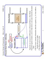
80386SX 16-bit Memory Interface (Separate Decoders)
A
0
A
15
O
0
O
7
...
...
CS
A
20
CS
CS
CS
CS
CS
CS
CS
M/IO
CS
CS
CS
CS
CS
CS
CS
A
0
A
15
O
0
O
7
...
...
CS
BHE
A
17
BLE
G2A
G2B
G1
A
B
C
0
1
2
3
4
5
6
7
74LS138
G2A
G2B
G1
A
B
C
0
1
2
3
4
5
6
7
(64K X 8)
62512
3
74LS138
A
18
A
19
A
21
A
22
A
23
Data Bus
D
0
to D
7
D
8
to D
15
80386SX
Separate Decoders
(64K X 8)
62512
WE
OE
MWTC
OE
WE
Address Bus
A
1
to A
16
G2A
G2B
G1
A
B
C
0
1
2
3
4
5
6
7
74LS138
MRDC
Systems Design & Programming Memory III CMPE 310
4 (Mar. 6, 2002)
UMBC
U M B C
U
N
I
V
E
R
S
I
T
Y
O
F
M
A
R
Y
L
A
N
D
B
A
L
T
I
M
O
R
E
C
O
U
N
T
Y
1
9
6
6
Memory Interfaces
See text for Separate Write Strobe scheme plus some examples of the integra-
tion of EPROM and SRAM in a complete system.
It is just an application of what we’ve been covering.
80386DX and 80486 have 32-bit data buses and therefore 4 banks of memory.
32-bit, 16-bit and 8-bit transfers are accomplished by different combina-
tions of the bank selection signals
BE3, BE2, BE1, BE0.
The Address bits A
0
and A
1
are used within the microprocessor to gener-
ate these signals.
They are don’t cares in the decoding of the 32-bit address outside the
chip (using a PLD such as the PAL 16L8).
The high clock rates of these processors usually require wait states for
memory access.
We will come back to this later.
Systems Design & Programming Memory III CMPE 310
5 (Mar. 6, 2002)
UMBC
U M B C
U
N
I
V
E
R
S
I
T
Y
O
F
M
A
R
Y
L
A
N
D
B
A
L
T
I
M
O
R
E
C
O
U
N
T
Y
1
9
6
6
Pentium Memory Interface
The Pentium, Pentium Pro, Pentium II and III contain a 64-bit data bus.
Therefore, 8 decoders or 8 write strobes are needed as well as 8 memory
banks.
The write strobes are obtained by combining the bank enable signals
(
BEx) with the MWTC signal.
MWTC is generated by combining the M/IO and W/R signals.
BE7
BE6
BE5
BE4
MWTC
BE3
BE2
BE1
BE0
WR7
WR6
WR5
WR4
WR3
WR2
WR1
WR0
W/R
M/
IO
Systems Design & Programming Memory III CMPE 310
6 (Mar. 6, 2002)
UMBC
U M B C
U
N
I
V
E
R
S
I
T
Y
O
F
M
A
R
Y
L
A
N
D
B
A
L
T
I
M
O
R
E
C
O
U
N
T
Y
1
9
6
6
Pentium Memory Interface
I1
I2
I3
I4
I5
I6
I7
I8
I9
I10
16L8
O1
O2
O3
O4
O5
O6
O7
O8
A29
A30
A31
I1
I2
I3
I4
I5
I6
I7
I8
I9
I10
16L8
O1
O2
O3
O4
O5
O6
O7
O8
A19
A20
A21
A22
A23
A24
A25
A26
A27
A28
A
0
A
15
O
0
O
7
...
...
CE
OE
27512
D
0
-D
7
D
8
-D
15
D
15
-D
23
D
24
-D
31
D
56
-D
63
D
48
-D
55
D
40
-D
47
D
32
-D
39
A3-A18
MRDC
A
0
A
15
O
0
O
7
...
...
CE
OE
27512
A
0
A
15
O
0
O
7
...
...
CE
OE
27512
A
0
A
15
O
0
O
7
...
...
CE
OE
27512
A
0
A
15
O
0
O
7
...
...
CE
OE
27512
A
0
A
15
O
0
O
7
...
...
CE
OE
27512
A
0
A
15
O
0
O
7
...
...
CE
OE
27512
A
0
A
15
O
0
O
7
...
...
CE
OE
27512
(64K X 8)
WE WE WE WE
WEWEWEWE
WR0
WR1
WR2
WR3
WR7
WR6
WR5
WR4
Systems Design & Programming Memory III CMPE 310
7 (Mar. 6, 2002)
UMBC
U M B C
U
N
I
V
E
R
S
I
T
Y
O
F
M
A
R
Y
L
A
N
D
B
A
L
T
I
M
O
R
E
C
O
U
N
T
Y
1
9
6
6
Pentium Memory Interface
In order to map previous memory into addr. space FFF80000H-FFFFFFFFH
Use a 16L8 to do the
WR0 - WR7 decoding using MWTC and BE0 - BE7.
See the text -- Figure 10-35.
;pins 1 2 3 4 5 6 7 8 9 10
A29 A30 A31 NC NC NC NC NC NC GND
;pins 11 12 13 14 15 16 17 18 19 20
U2 CE NC NC NC NC NC NC NC VCC
Equations:
/CE = /U2 * A29 * A30 * A31
I1
I2
I3
I4
I5
I6
I7
I8
I9
I10
16L8
O1
O2
O3
O4
O5
O6
O7
O8
A29
A30
A31
I1
I2
I3
I4
I5
I6
I7
I8
I9
I10
16L8
O1
O2
O3
O4
O5
O6
O7
O8
A19
A20
A21
A22
A23
A24
A25
A26
A27
A28
;pins 1 2 3 4 5 6 7 8 9 10
A19 A20 A21 A22 A23 A24 A25 A26 A27 GND
;pins 11 12 13 14 15 16 17 18 19 20
A28 U2 NC NC NC NC NC NC NC VCC
Equations:
/U2 = A19 * A20 * A21 * A22 * A23 * A24 * A25 *
A26 * A27 * A28