Chuẩn truyền tin Hart trong đo lường và điều khiển tự động mạng công nghiệp
Bạn đang xem bản rút gọn của tài liệu. Xem và tải ngay bản đầy đủ của tài liệu tại đây (1.41 MB, 141 trang )
Chuẩn truyền tin HART- Highway Addressable Remote Tranducer
----------------------------------------------------------------------------------------------------
-----------------------------------------------------------------------------------------------
Bộ môn: Tự động hóa – Khoa Điện – Trường ĐHBK Đà Nẵng
1
TRƯỜNG ĐẠI HỌC BÁCH KHOA
KHOA ĐIỆN
BỘ MÔN : TỰ ĐỘNG HÓA
CHUẨN TRUYỀN TIN
HART
TRONG ĐO LƯỜNG VÀ ĐIỀU KHIỂN TỰ ĐỘNG
MẠNG CÔNG NGHIỆP
Version 1.0 – Lưu hành nội bộ
ĐÀ NẴNG 2007
Chuẩn truyền tin HART- Highway Addressable Remote Tranducer
----------------------------------------------------------------------------------------------------
-----------------------------------------------------------------------------------------------
Bộ môn: Tự động hóa – Khoa Điện – Trường ĐHBK Đà Nẵng
2
GIỚI THIỆU CHUNG
HART là một giao thức truyền thông được giới thiệu vào năm 1980, những ứng dụng của
HART được phát triển bởi tổ chức HCF. HART cho phép thiết bị làm việc trong môi
trường công nghiệp có nhiễu cao và tương thích với các chuẩn 4-20mA. Nó được kiến
trúc dựa trên sự xếp chồng tín hiệu số trên nền tín hiệu tương tự 4 – 20mA, nghĩa là nó có
dạng tín hiệu lai, cộng tín hiệu một chiều với tín hiệu đã được mã hóa. Do đó các thiết bị
có thể nhanh chóng định dạng và xác định đúng thông số cần dùng khi có nhiều thiết bị
nối vào chung mạng công nghiệp. Cũng như các chuẩn công nghiệp đã có trong lịch sử,
để người sử dụng và các môi trường tiếp nhận không bị ảnh hưởng về tâm lí vật lí, HART
cũng cho phép nối Master-Slave dạng PPI và MPI.
Các liên kết PPI cho phép kéo dài đường truyền đến 3000m và MPI là 1500m, tối đa của
MPI lến đến 15 thiết bị. Tuy nhiên HART có nhược điểm là tốc độ truyền thấp, hiện nay
đến 4800 baud. Ngược lại, HART lại cho phép cả thiết bị tương tự và số có thể làm việc
trên cùng một mạng. Sau đây sẽ trình bày cụ thể hơn những đặc điểm cơ bản về HART.
Tài liệu sau đây vừa trình bày những kiến thức về HART, đồng thời cũng đưa ra những
mạch điện cụ thể sử dụng cho các chuẩn đo lượng hiện đại hiện nay. Sinh viên có thể sử
dụng các phần kiến thức đó để phục vụ cho quá trình làm bài tập, đồ án môn học, tốt
nghiệp và các công tác khác sau này.
Chuẩn truyền tin HART- Highway Addressable Remote Tranducer
----------------------------------------------------------------------------------------------------
-----------------------------------------------------------------------------------------------
Bộ môn: Tự động hóa – Khoa Điện – Trường ĐHBK Đà Nẵng
3
About HART -- Part 1
Part1: Preliminaries
Introduction
HART (Highway Addressable Remote Transducer) provides digital communication to
microprocessor-based (smart) analog process control instruments. Originally intended to allow
convenient calibration, range adjustment, damping adjustment, etc. of analog process
transmitters; it was the first bi-directional digital communication scheme for process transmitters
that didn't disturb the analog signal. The process could be left running during communication.
HART has since been extended to process receivers, and is sometimes also used in data
acquisition and control. HART Specifications continue to be updated to broaden the range of
HART applications. And a recent HART development, the Device Description Language
(DDL), provides a universal software interface to new and existing devices.
HART was developed in the early 1980s by Rosemount Inc. [1.4]. Later, Rosemount made it
an open standard. Since then it has been organized and promoted by the HART Communication
Foundation [1.5], which boasts some 114 member companies.
As the de-facto standard for data communication in smart analog field instruments, HART is
found in applications ranging from oil pipelines to pulp and paper mills to public utilities. As of
June 1998 an estimated 5 million nodes were installed [1.1]. Among the many HART products
now available are
Analog Process Transmitters
Digital-only Process Transmitters
Multi-variable Process Transmitters
Process Receivers (Valves)
Local (Field) Controllers
HART-to-Analog Converters
Modems, Interfaces, and Gateways
HART-compatible Intrinsic Safety Barriers
HART-compatible Isolators
Calibrators
Software Packages
New HART products continue to be announced, despite encroachment by Foundation Fieldbus
and other faster networks. Analog transmitters continue to flourish [1.2
], which suggests that
HART will, also. A recent study [1.3] predicts that, of all smart pressure transmitters sold in the
next few years, sales of HART units will increase at 17.5% per year.
Analog Services, Inc., a leader in HART development, is pleased to present this on-line book
about HART. We have tried to present many topics that do not appear in the HART Standards or
App Notes. This is still a work in progress. If there are other topics that you would like to see
Chuẩn truyền tin HART- Highway Addressable Remote Tranducer
----------------------------------------------------------------------------------------------------
-----------------------------------------------------------------------------------------------
Bộ môn: Tự động hóa – Khoa Điện – Trường ĐHBK Đà Nẵng
4
covered or corrections to what we have presented, please send us an e-mail at
Overview: HART and The Conventional Process Loop
HART is sometimes best understood by looking at how it evolved from a conventional process
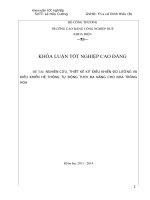
loop. Figure 1.1 is a simplified diagram of the familiar analog current loop. The process
transmitter signals by varying the amount of current flowing through itself. The controller
detects this current variation by measuring the voltage across the current sense resistor. The loop
current varies from 4 to 20 mA at frequencies usually under 10 Hz.
Figure 1.1 -- Conventional Process Loop
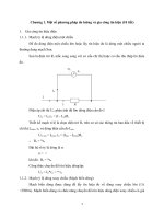
Figure 1.2 is the same thing with HART added. Both ends of the loop now include a modem and
a "receive amplifier." The receive amplifier has a relatively high input impedance so that it
doesn't load the current loop. The process transmitter also has an AC-coupled current source, and
the controller an AC-coupled voltage source. The switch in series with the voltage source (Xmit
Volt Source) in the HART controller is normally open. In the HART Controller the added
components can be connected either across the current loop conductors, as shown, or across the
current sense resistor. From an AC standpoint, the result is the same, since the Pwr Supply is
effectively a short circuit. Notice that all of the added components are AC-coupled, so that they
do not affect the analog signal. The receive amplifier is often considered part of the modem and
would usually not be shown separately. We did it this way to indicate how (across which nodes)
the receive signal voltage is derived. In either the Controller or the Transmitter, the receive
signal voltage is just the AC voltage across the current loop conductors.
Chuẩn truyền tin HART- Highway Addressable Remote Tranducer
----------------------------------------------------------------------------------------------------
-----------------------------------------------------------------------------------------------
Bộ môn: Tự động hóa – Khoa Điện – Trường ĐHBK Đà Nẵng
5
Figure 1.2 -- Process Loop With HART Added
To send a HART message, the process transmitter turns ON its AC-coupled current source.
This superimposes a high-frequency carrier current of about 1 mA p-p onto the normal
transmitter output current. The current sense resistor at the controller converts this variation into
a voltage that appears across the two loop conductors. The voltage is sensed by the controller's
receive amplifier and fed to the controller's demodulator (in block labeled "modem"). In practice
the two current sources in the HART process transmitter are usually implemented as a single
current regulator; and the analog and digital (HART) signals are combined ahead of the regulator.
To send a HART message in the other direction (to the process transmitter), the HART
Controller closes its transmit switch. This effectively connects the "Xmit Volt Source" across the
current loop conductors, superimposing a voltage of about 500 mV p-p across the loop
conductors. This is seen at the process transmitter terminals and is sent to its receive amplifier
and demodulator.
Figure 1.2 implies that a Master transmits as voltage source, while a Slave transmits as a
current source. This is historically true. It is also historically true that the lowest impedance in
the network -- the one that dominates the current-to-voltage conversion -- was the current sense
resistor. Now, with some restrictions, either device can have either a low or high impedance.
And the current sense resistor doesn't necessarily dominate.
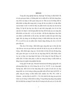
Regardless of which device is sending the HART message, the voltage across the loop
conductors will look something like that of figure 1.3; with a tiny burst of carrier voltage
superimposed on a relatively large DC voltage. The superimposed carrier voltage will have a
range of values at the receiving device, depending on the size of the current sense resistor, the
amount of capacitive loading, and losses caused by other loop elements. Of course the DC
Chuẩn truyền tin HART- Highway Addressable Remote Tranducer
----------------------------------------------------------------------------------------------------
-----------------------------------------------------------------------------------------------
Bộ môn: Tự động hóa – Khoa Điện – Trường ĐHBK Đà Nẵng
6
voltage will also vary; depending on controller supply voltage, loop resistance, where in the loop
the measurement is made, etc.
Figure 1.3 -- HART Carrier Burst
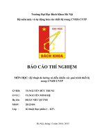
HART communication is FSK (frequency-shift-keying), with a frequency of 1200 Hz
representing a binary one and a frequency of 2200 Hz representing a binary zero. These
frequencies are well above the analog signaling frequency range of 0 to 10 Hz, so that the HART
and analog signals are separated in frequency and ideally do not interfere with each other. The
HART signal is typically isolated with a high-pass filter having a cut-off frequency in the range
of 400 Hz to 800 Hz. The analog signal is similarly isolated with a low-pass filter. This is
illustrated in figure 1.4.
Chuẩn truyền tin HART- Highway Addressable Remote Tranducer
----------------------------------------------------------------------------------------------------
-----------------------------------------------------------------------------------------------
Bộ môn: Tự động hóa – Khoa Điện – Trường ĐHBK Đà Nẵng
7
Figure 1.4 -- Separation of Analog and HART (Digital) Signals
The separation in frequency between HART and analog signaling means that they can coexist on
the same current loop. This feature is essential for HART to augment traditional analog
signaling. Further information on the frequencies involved in HART transmission is given in the
section entitled HART Signal Power Spectral Density. For a description of FSK and other
forms of data/digital communication, see [3.5].
For convenience, Figure 1.4 shows the Analog and HART Signals to be the same level.
Generally, this isn't true. The Analog Signal can vary from 4 to 20 mA or 16 mA p-p (unusual,
but possible), which is vastly larger than the HART Signal. This, in turn, can lead to some
difficulties in separating them.
HART is intended to retrofit to existing applications and wiring. This means that there must
be 2-wire HART devices. It also means that devices must be capable of being intrinsically safe.
These requirements imply relatively low power and the ability to transmit through intrinsic safety
barriers. This is accomplished through a relatively low data rate, low signal amplitude, and
superposition of the HART and analog signals. Power consumption is further reduced through
the half-duplex nature of HART. That is, a device does not simultaneously transmit and receive.
Therefore, some receive circuits can be shut down during transmit and vice-versa.
Intrinsic Safety and retrofitting to existing applications and wiring also explain why HART
was developed at all, despite other advanced communication systems and techniques that existed
at the time. None of them would have met the low power requirements needed in a 2-wire 4-20
mA device. Further information on intrinsically safe HART devices is given in the section
entitled HART and Intrinsic Safety
.
In HART literature the process transmitter is called a Field Instrument or HART Slave
Device. (These terms will be used interchangeably throughout our presentation.) And the
current loop is a network.
The controller is a HART Master. A hand-held communicator can
Chuẩn truyền tin HART- Highway Addressable Remote Tranducer
----------------------------------------------------------------------------------------------------
-----------------------------------------------------------------------------------------------
Bộ môn: Tự động hóa – Khoa Điện – Trường ĐHBK Đà Nẵng
8
also be placed across the network temporarily. It is used in place of, or in addition to, the fixed
controller-based HART Master. When both types of Masters are present, the controller is the
Primary Master and the hand-held unit is the Secondary Master. (Note: It becomes difficult to
describe process devices in a data communication setting, because the terms transmitter and
receiver have more than one meaning. For example, a process transmitter both receives and
transmits data bits. We hope we've avoided confusion by providing sufficient context whenever
these words are used.)
HART now includes process receivers. These are also called Field Instruments or HART
Slaves and are discussed in the section entitled Process Receiver.
Overview: Signaling
The HART signal path from the the processor in a sending device to the processor in a
receiving device is shown in figure 1.5. Amplifiers, filters, etc. have been omitted for
simplicity. At this level the diagram is the same, regardless of whether a Master or Slave is
transmitting. Notice that, if the signal starts out as a current, the "Network" converts it to a
voltage. But if it starts out a voltage it stays a voltage.
Figure 1.5 -- HART Signal Path
The transmitting device begins by turning ON its carrier and loading the first byte to be
transmitted into its UART. It waits for the byte to be transmitted and then loads the next one.
This is repeated until all the bytes of the message are exhausted. The transmitter then waits for
the last byte to be serialized and finally turns off its carrier. With minor exceptions, the
transmitting device does not allow a gap to occur in the serial stream.
Chuẩn truyền tin HART- Highway Addressable Remote Tranducer
----------------------------------------------------------------------------------------------------
-----------------------------------------------------------------------------------------------
Bộ môn: Tự động hóa – Khoa Điện – Trường ĐHBK Đà Nẵng
9
The UART converts each transmitted byte into an 11 bit serial character, as in figure 1.6. The
original byte becomes the part labeled "Data Byte (8 bits)". The start and stop bits are used for
synchronization. The parity bit is part of the HART error detection. These 3 added bits
contribute to "overhead" in HART communication.
Figure 1.6 -- HART Character Structure
The serial character stream is applied to the Modulator of the sending modem. The Modulator
operates such that a logic 1 applied to the input produces a 1200 Hz periodic signal at the
Modulator output. A logic 0 produces 2200 Hz. The type of modulation used is called
Continuous Phase Frequency Shift Keying (CPFSK). "Continuous Phase" means that there is no
discontinuity in the Modulator output when the frequency changes. A magnified view of what
happens is illustrated in figure 1.7 for the stop bit to start bit transition. When the UART output
(modulator input) switches from logic 1 to logic 0, the frequency changes from 1200 Hz to 2200
Hz with just a change in slope of the transmitted waveform. A moment's thought reveals that the
phase doesn't change through this transition. Given the chosen shift frequencies and the bit rate,
a transition can occur at any phase.
Chuẩn truyền tin HART- Highway Addressable Remote Tranducer
----------------------------------------------------------------------------------------------------
-----------------------------------------------------------------------------------------------
Bộ môn: Tự động hóa – Khoa Điện – Trường ĐHBK Đà Nẵng
10
Figure 1.7 -- Illustration of Continuous Phase FSK
A mathematical description of continuous phase FSK is given in the section entitled Equation
Describes CPFSK.
The form of modulation used in HART is the same as that used in the "forward channel" of
Bell-202. However, there are enough differences between HART and Bell-202 that several
modems have been designed specifically for HART. Further information on Bell-202 is given in
the section entitled What's In a Bell-202 Standard?
At the receiving end, the demodulator section of a modem converts FSK back into a serial bit
stream at 1200 bps. Each 11-bit character is converted back into an 8-bit byte and parity is
checked. The receiving processor reads the incoming UART bytes and checks parity for each
one until there are no more or until parsing of the data stream indicates that this is the last byte of
the message. The receiving processor accepts the incoming message only if it's amplitude is
high enough to cause carrier detect to be asserted. In some cases the receiving processor will
have to test an I/O line to make this determination. In others the carrier detect signal gates the
receive data so that nothing (no transitions) reaches the receiving UART unless carrier detect is
asserted.
Overview: HART Process Transmitter Block Diagram
A block diagram of a typical HART Process Transmitter is given in figure 1.8.
Chuẩn truyền tin HART- Highway Addressable Remote Tranducer
----------------------------------------------------------------------------------------------------
-----------------------------------------------------------------------------------------------
Bộ môn: Tự động hóa – Khoa Điện – Trường ĐHBK Đà Nẵng
11
Figure 1.8 -- Typical HART Process Transmitter Block Diagram
The "network interface" in this case is the current regulator. The current regulator implements
the two current sources shown in the "process transmitter" of figure 1.2. The block labeled
"modem", and possibly the block labeled "EEPROM", are about the only parts that would not
otherwise be present in a conventional analog transmitter. The EEPROM is necessary in a
HART transmitter to store fundamental HART parameters. The UART, used to convert between
serial and parallel data, is often built into the micro-controller and does not have to be added as a
separate item.
The diagram illustrates part of the appeal of HART: its simplicity and the relative ease with
which HART field instruments can be designed. HART is essentially an add-on to existing
analog communication circuitry. The added hardware often consists of only one extra integrated
circuit of any significance, plus a few passive components. In smart field instruments the ROM
and EEPROM to hold HART software and HART parameters will usually already exist.
Overview: Building Networks
The type of network thus far described, with a single Field Instrument that does both HART
and analog signaling, is probably the most common type of HART network and is called a point-
to-point network. In some cases the point-to-point network might have a HART Field
Instrument but no permanent HART Master. This might occur, for example, if the User intends
primarily analog communication and Field Instrument parameters are set prior to installation. A
HART User might also set up this type of network and then later communicate with the Field
Instrument using a hand-held communicator (HART Secondary Master). This is a device that
clips onto device terminals (or other points in the network) for temporary HART communication
with the Field Instrument.
A HART Field Instrument is sometimes configured so that it has no analog signal -- only
HART. Several such Field Instruments can be connected together (electrically in parallel) on the
same network, as in figure 1.9.
Chuẩn truyền tin HART- Highway Addressable Remote Tranducer
----------------------------------------------------------------------------------------------------
-----------------------------------------------------------------------------------------------
Bộ môn: Tự động hóa – Khoa Điện – Trường ĐHBK Đà Nẵng
12
Figure 1.9 -- HART Network with Multi-dropped Field Instruments
These Field Instruments are said to be multi-dropped. The Master is able to talk to and configure
each one, in turn. When Field Instruments are multi-dropped there can't be any analog signaling.
The term "current loop" ceases to have any meaning. Multi-dropped Field Instruments that are
powered from the network draw a small, fixed current (usually 4 mA); so that the number of
devices can be maximized. A Field Instrument that has been configured to draw a fixed analog
current is said to be "parked." Parking is accomplished by setting the short-form address of the
Field Instrument to some number other than 0. A hand-held communicator might also be
connected to the network of figure 1.9.
There are few restrictions on building networks. The topology may be loosely described as a
bus, with drop attachments forming secondary busses as desired. This is illustrated in figure
1.10. The whole collection is considered a single network. Except for the intervening lengths of
cable, all of the devices are electrically in parallel. The Hand-Held Communicator (HHC) may
also be connected virtually anywhere. As a practical matter, however, most of the cable is
inaccessible and the HHC has to be connected at the Field Instrument, in junction boxes, or in
controllers or marshalling panels.
Chuẩn truyền tin HART- Highway Addressable Remote Tranducer
----------------------------------------------------------------------------------------------------
-----------------------------------------------------------------------------------------------
Bộ môn: Tự động hóa – Khoa Điện – Trường ĐHBK Đà Nẵng
13
Figure 1.10 -- HART Network Showing Free Arrangement of Devices
In intrinsically safe (IS) installations there will likely be an IS barrier separating the Control and
Field areas.
A Field Instrument may be added or removed or wiring changes made while the network is
live (powered). This may interrupt an on-going transaction. Or , if the network is inadvertently
short-circuited, this could reset all devices. The network will recover from the loss of a
transaction by re-trying a previous communication. If Field Instruments are reset, they will
eventually come back to the state they were in prior to the reset. No reprogramming of HART
parameters is needed.
The common arrangement of a home run cable, junction box, and branch cables to Field
Instruments is acceptable. Different twisted pairs of the same cable can be used as separate
HART networks powered from a single supply, as in figure 1.11. Notice that in this example the
2nd network has two multi-dropped Field Instruments, while each of the other two networks
shown has only one.
Chuẩn truyền tin HART- Highway Addressable Remote Tranducer
----------------------------------------------------------------------------------------------------
-----------------------------------------------------------------------------------------------
Bộ môn: Tự động hóa – Khoa Điện – Trường ĐHBK Đà Nẵng
14
Figure 1.11 -- Single Cable With Multiple HART Networks
Circuit 1 in the diagram is connected to A/D converter 1 and Modem 1. Circuit 2 is connected to
A/D converter 2, Modem 2. And so on. Or else a multiplexor may be used to switch a single
A/D converter or single Modem sequentially from Circuit 1 through Circuit N. If a single
Modem is used, it is either a conventional Modem that is switched in between HART
transactions; or it could be a special sampled-data type of Modem that is able to operate on all
networks simultaneously.
HART networks use shielded twisted pair cable. Many different cables with different
characteristics are used. Although twisted pair cable is used, the signaling is single-ended. (One
side of each pair is at AC ground.) HART needs a minimum bandwidth (-3 dB) of about 2.5
kHz. This limits the total length of cable that can be used in a network. The cable capacitance
(and capacitance of devices) forms a pole with a critical resistance called the network resistance.
In most cases the network resistance is the same as the current sense resistance in figures 1.1 and
1.2. To insure a pole frequency of greater than 2.5 kHz, the RC time constant must be less than
65 microsecond. For a network resistance of 250 ohm, C is a maximum of 0.26 microfarad.
Thus, the capacitance due to cable and other devices is limited to 0.26 microfarad. Further
information on cable effects is given in the section entitled Cable Effects.
Digital signaling brings with it a variety of other possible devices and modes of operation. For
example, some Field Instruments are HART only and have no analog signaling. Others draw no
power from the network. In still other cases the network may not be powered (no DC). There
also exist other types of HART networks that depart from the conventional one described here.
These are covered in the section entitled HART Gateways and Alternative Networks
.
Overview: Protocol
Chuẩn truyền tin HART- Highway Addressable Remote Tranducer
----------------------------------------------------------------------------------------------------
-----------------------------------------------------------------------------------------------
Bộ môn: Tự động hóa – Khoa Điện – Trường ĐHBK Đà Nẵng
15
Normally, one HART device talks while others listen. A Master typically sends a command
and then expects a reply. A Slave waits for a command and then sends a reply. The command
and associated reply are called a transaction. There are typically periods of silence (nobody
talking) between transactions. The two bursts of carrier during a transaction are illustrated in
figure 1.12.
Figure 1.12 -- Carrier Bursts During HART Transaction
There can be one or two Masters (called Primary and Secondary Masters) per network. There
can be (from a protocol viewpoint) almost an unlimited number of Slaves. (To limit noise on a
given network, the number of Slaves is limited to 15. If the network is part of a super network
involving repeaters, then more Slaves are possible because the repeater re-constitutes the digital
signal so that noise does not pass through it.)
A Slave accesses the network as quickly as possible in response to a Master. Network access
by Masters requires arbitration. Masters arbitrate by observing who sent the last transmission (a
Slave or the other Master) and by using timers to delay their own transmissions. Thus, a Master
allows time for the other Master to start a transmission. The timers constitute dead time when no
device is communicating and therefore contribute to "overhead" in HART communication.
Further information on Master arbitration is available in the section entitled Timing is
Everything.
A Slave (normally) has a unique address to distinguish it from other Slaves. This address is
incorporated into the command message sent by a Master and is echoed back in the reply by the
Slave. Addresses are either 4 bits or 38 bits and are called short and long or "short frame" and
"long frame" addresses, respectively. A Slave can also be addressed through its tag (an identifier
assigned by the user). HART Slave addressing and the reason for two different address sizes is
discussed in more detail in the next section.
Each command or reply is a message, varying in length from 10 or 12 bytes to typically 20 or
30 bytes. The message consists of the elements or fields listed in table 1.1, starting with the
preamble and ending with the checksum.
Chuẩn truyền tin HART- Highway Addressable Remote Tranducer
----------------------------------------------------------------------------------------------------
-----------------------------------------------------------------------------------------------
Bộ môn: Tự động hóa – Khoa Điện – Trường ĐHBK Đà Nẵng
16
Part of Message Length in Bytes Purpose
Preamble 5 to 20
Synchronization &
Carrier Detect
Start Delimiter 1
Synchronization &
Shows Which Master
Address 1 or 5
Choose Slave, Indicate
Which Master, and
Indicate Burst Mode
Command 1 Tell Slave What to Do
Number Data Bytes 1
Indicates Number Bytes
Between Here and
Checksum
Status
0 (if Master)
2 (if Slave)
Slave Indicates Its
Health and Whether it
did As Master Intended
Data 0 to 253
Argument Associated
with Command (Process
Variable, For Example)
Checksum 1 Error Control
Table 1.1 -- Parts of HART Message
The preamble is allowed to vary in length, depending on the Slave's requirements. A Master
will use the longest possible preamble when talking to a Slave for the first time. Once the Master
reads the Slave's preamble length requirement (a stored HART parameter), it will subsequently
use this new length when talking to that Slave. Different Slaves can have different preamble
length requirements, so that a Master might need to maintain a table of these values.
A longer preamble means slower communication. Slave devices are now routinely designed so
that they need only a 5 byte preamble; and the requirement for a variable preamble length may
now be largely historical.
The status field (2 bytes) occurs only in replies by HART Slave devices. If a Slave does not
execute a command, the status shows this and usually indicates why. Several possible reasons
are:
1. The Slave received the message in error. (This can also result in no reply.)
2. The Slave doesn't implement this command.
3. The Slave is busy.
4. The Slave was told to do something outside of its capability
(range number too large or small, for example).
Chuẩn truyền tin HART- Highway Addressable Remote Tranducer
----------------------------------------------------------------------------------------------------
-----------------------------------------------------------------------------------------------
Bộ môn: Tự động hóa – Khoa Điện – Trường ĐHBK Đà Nẵng
17
5. The Slave is write-protected and was told to change a protected parameter.
A Slave Device will often be equipped with write-protect capability. This is often implemented
with a two-position shorting block on the device's circuit board. With the shorting block in the
write-protect position, parameters can't be changed. A Slave that is commanded to change a
protected parameter will not act on the command and will reply that it is write protected.
Commands are one of 3 types: Universal, Common Practice, and Device Specific
(Proprietary). Universal and Common Practice commands implement functions that were either
part of an original set or are needed often enough to be specified as part of the Protocol. Among
the Universal commands are commands to read and write the device's serial number, tag,
descriptor, date; read and write a scratch memory area; read the device's revision levels; and so
on. These parameters are semi-permanent and are examples of data that is stored in EEPROM.
A Device Specific command is one that the device manufacturer creates. It can have any
number from 128 to 253. Different manufacturers may use the same command number for
entirely different functions. Therefore, the Master must know the properties of the devices it
expects to talk to. The HART Device Description Language is helpful in imparting this
information to a Master. The command value 255 is not allowed, to avoid possible confusion
with the preamble character. The value 254 is reserved -- probably to allow for a second
command byte in future devices that may require a very large number of device-specific
commands.
The checksum at the end of the message is used for error control. It is the exclusive-or of all of
the preceding bytes, starting with the start delimiter. The checksum, along with the parity bit in
each character, create a message matrix having so-called vertical and longitudinal parity. If a
message is in error, this usually necessitates a retry. Further information on HART error control
is given below in the section HART Message Errors.
One more feature, available in some Field Instruments, is burst mode. A Field Instrument that
is burst-mode capable can repeatedly send a HART reply without a repeated command. This is
useful in getting the fastest possible updates (about 2 to 3 times per second) of process variables.
If burst-mode is to be used, there can be only one bursting Field Instrument on the network.
A Field Instrument remembers its mode of operation during power down and returns to this
mode on power up. Thus, a Field Instrument that has been parked will remain so through power
down. Similarly, a Field Instrument in burst-mode will begin bursting again on power up.
HART Protocol puts most of the responsibility (such as timing and arbitration) into the
Masters. This eases the Field Instrument software development and puts the complexity into the
device that's more suited to deal with it.
A large amount of Protocol information, including message structure and examples, is given in
[1.6].
Chuẩn truyền tin HART- Highway Addressable Remote Tranducer
----------------------------------------------------------------------------------------------------
-----------------------------------------------------------------------------------------------
Bộ môn: Tự động hóa – Khoa Điện – Trường ĐHBK Đà Nẵng
18
Overview: Addressing
Each HART field instrument must have a unique address. Each command sent by a Master
contains the address of the desired Field Instrument. All Field Instruments examine the
command. The one that recognizes its own address sends back a response. For various reasons
HART addressing has been changed a few times. Each change had to be done in such a way as to
maintain backward compatibility. This has led to some confusion over addressing. Hopefully,
this somewhat chronological presentation will not add to the confusion.
Early HART protocol used only a 4 bit address. This meant there could be 16 field instruments
per network. In any Field Instrument the 4-bit address could be set to any value from 0 to 15
using HART commands. If a Master changed the address of a Field Instrument, it would have to
use the new address from then on when talking to that particular Field Instrument.
Later, HART was modified to use a combination of the 4-bit address and a new 38 bit address.
In these modern devices, the 4-bit address is identical to the 4-bit address used exclusively in
earlier devices, and is also known as a polling address or short address. The 38 bit address is also
known as the long address, and is permanently set by the Field Instrument manufacturer. A 38-
bit address allows virtually an unlimited number of Field Instruments per network. Older
devices that use only a 4-bit address are also known as "rev 4" Field Instruments. Modern
devices, that use the combined addresses, are also known as "rev 5" instruments. These
designations correspond to the revision levels of the HART Protocol documents. Revision 4
devices are now considered obsolete. Their sale or use or design is discouraged and most
available software is probably not compatible with revision 4.
So, why the two forms of address in modern Field Instruments? The reason is that we need a
way of quickly determining the long address. We can't just try every possible combination (2 to
the 38th power). This would take years. So, instead, we put the old 4-bit address to work. We
use it to get the Field Instrument to divulge its long address. The protocol rules state that HART
Command 0 may be sent using the short address. All other commands require the long address.
Command 0, not surprisingly, commands a Field Instrument to tell us its long address. In effect
the short address is used only once, to tell us how to talk to the Field Instrument using its long
address.
The long address consists of the lower (least significant) 38 bits of a 40-bit unique identifier.
This is illustrated in figure 1.13. The first byte of the unique identifier is the manufacturer's ID
number. The second is the manufacturer's device type code. The 3rd, 4th, and 5th are a serial
number. It is intended that no two Field Instruments in existence have the same 40-bit identifier.
Chuẩn truyền tin HART- Highway Addressable Remote Tranducer
----------------------------------------------------------------------------------------------------
-----------------------------------------------------------------------------------------------
Bộ môn: Tự động hóa – Khoa Điện – Trường ĐHBK Đà Nẵng
19
Figure 1.13 -- Unique Identifier and Long Address
There is an another way to get a Field Instrument to divulge its long address: By using its tag.
A tag is a 6-byte identification code that an end-user may assign to a Field Instrument. Once this
assignment is made, Command 11 will provide the same information as command 0. But
command 11 is one of those that require a long address. This seems to present a chicken-and-egg
dilemma: We want to use command 11 to learn the long address. But we need to know the long
address to use command 11. Obviously, there is a way around this. It is to use a broadcast
address. The broadcast address has all 38 bits equal to zero and is a way of addressing all Field
Instruments at once. When a Field Instrument sees this address and command 11, it compares its
tag against the one included in the command. If they match, then the Field Instrument sends a
reply. Since there should be only one Field Instrument with a matching tag, only one should
reply.
The short address in either the older or modern Field Instruments has one other purpose: to
allow parking. A parked Field Instrument has its analog output current fixed. Usually it is fixed
at some low value such as 4 mA. Parking is necessary for multi-dropped instruments to avoid a
large and meaningless current consumption. A Field Instrument is parked by setting its short
address to a value other than 0. In other words, the short address of the parked Field Instrument
can be any value from 1 through 15.
Some HART-only Field Instruments have no Analog Signal and are effectively parked for any
short address from 0 through 15.
There are potential problems with the HART addressing scheme. These are discussed in the
section entitled Addressing Problems, Slave Commissioning, and Device Database.
Overview: Conclusion
Although some of the details and variations are left out, this is basically how HART works.
The complete topology rules and device requirements are given in HART specifications, which
are sold by the HART Communication Foundation [1.5]. The information presented here should
Chuẩn truyền tin HART- Highway Addressable Remote Tranducer
----------------------------------------------------------------------------------------------------
-----------------------------------------------------------------------------------------------
Bộ môn: Tự động hóa – Khoa Điện – Trường ĐHBK Đà Nẵng
20
not be considered a substitute for the actual specifications. A current list of the specifications and
their HCF designations is given in the section entitled Table of Current HART Publications .
Some circuit designs and more detail on selected HART topics are covered in the HART
Application Note.
Why So Slow?
A common question or complaint about HART is its relatively low speed of 1200 bps. In an
age of DSL, HART is clearly a snail. One has to keep in mind the time period in which HART
was developed (early 1980's) as well as the relatively small amount of available power in 4-20
mA analog instruments. In the early 1980s, a 300 bps modem for a personal computer was
considered pretty good. And when 1200 bps modems came out, they sold for $500 to $600 each.
The power to run personal computer modems has always been watts. The power to run a HART
modem is often only 2 mW.
Not only is there very little power available in analog instruments, but it keeps shrinking!
Demands for greater functionality keep shifting the available current into more powerful
processors, etc.
Some of the issues/problems involved in a higher speed HART are:
1. Many of the protocol functions must be moved into hardware. A single low-power
microcontroller in a Slave device would otherwise be hard-pressed to keep up.
2. Backward compatibility with devices/networks that run at the current speed and
and use the existing bandwidth. If the bit rate is to be higher than the existing
bandwidth of 3 or 4 kHz, this generally means that spectrally efficient techniques
are needed. This loosely translates into complicated modulation methods and
digital signal processing. Thus, there is a quantum leap in current consumption.
3. The cost of a larger and more complex HART chip.
4. Burst type operation, which is used in HART becomes difficult to achieve at higher bit
rates, because of the need for long equalization periods and other receiver start-up
activities.
The HART Communication Foundation has actively sought and invested in the development of a
higher speed HART. But so far the hardware has not materialized.
For information on the theoretical upper speed limit for a HART network, see the section
entitled How Fast?
Too see our proposal for a higher speed HART, click here.
Chuẩn truyền tin HART- Highway Addressable Remote Tranducer
----------------------------------------------------------------------------------------------------
-----------------------------------------------------------------------------------------------
Bộ môn: Tự động hóa – Khoa Điện – Trường ĐHBK Đà Nẵng
21
What's In A Bell-202 Standard?
If you've searched through the various Bell-202 Standards and wondered where the FSK
modulation and the shift frequencies appear, the answer is they don't. Not even the bit rate of
1200 bps is stated, although it is the recommended upper limit for PSTN (dial-up lines). The bit
rate (1200 bps), type of modulation (CPFSK), and the shift frequencies (1200 Hz and 2200 Hz)
are all de facto values used in Bell-202 modems. Apparently, just as J.S. Bach never put dynamic
markings in his music, believing that it would never be performed other than under his direction;
Ma Bell never put in this vital information, thinking that she would forever have a monopoly on
modems.
Process Receiver
HART was originally conceived to augment process transmitters. However, specifications
were later revised to cover process receivers (typically valve positioners), as well. Here, we will
briefly examine the electrical characteristics of a HART process receiver.
In a conventional process receiver loop, the controller generates a 4-20 mA current that is
applied to (passed through) the process receiver. The desired characteristic of the receiver is that
it have an impedance of almost zero. This is the opposite of the process transmitter, which
ideally has infinite impedance. Thus, the two types of Field Instruments are electrical opposites.
To add HART communication to the process receiver loop, we could perpetuate the existing
impedance situation and require high-impedance Masters and low-impedance Field Instruments.
This would require a new set of HART Masters that would transmit using a current source
instead of a voltage source. In fact there would be a duplication of most of the HART elements
that already exist for process transmitter loops; and possibly a separate specification and separate
products for process receiverdom.
Another approach -- a more practical one -- is to devise a process receiver with nearly zero
impedance at DC and a high impedance at HART frequencies. Using this approach, a single type
of HART Master is able to talk to either a process transmitter or a process receiver. It is easier to
make such a HART process receiver if the "high impedance" doesn't have to be too high. About
300 to 400 ohm is about as high as it can easily go. Since this is still relatively low, the HART
specifications permit this device to set the network resistance. That is, the impedance of this
device at HART frequencies replaces the current sense resistor. Note that a current sense resistor
wouldn't normally be present, anyway, in a process receiver loop. The complete process receiver
loop with HART components is shown in figure 1.14. The frequency-dependent impedance in
the process receiver is represented by the small graph of |Z| versus frequency.
Chuẩn truyền tin HART- Highway Addressable Remote Tranducer
----------------------------------------------------------------------------------------------------
-----------------------------------------------------------------------------------------------
Bộ môn: Tự động hóa – Khoa Điện – Trường ĐHBK Đà Nẵng
22
Figure 1.14 -- Process Receiver Loop Circuitry
Although the figure shows the transmit source in the process receiver as a current source, this
could probably also be implemented as a switched voltage source.
There are actually two types of process receivers. The second type is electrically the same as a
process transmitter, except that it draws a fixed current and the position is set by writing a
setpoint with a HART command. This allows the process receiver to be multi-dropped with other
similar receivers or other HART devices. There are also smart positioners that incorporate both
types of HART interface for maximum versatility.
Other Books About HART?
As far as we know there aren't any. A search of amazon.com (on-line bookstore) turned up
nothing. The Instrument Society of America (ISA) publishes a variety of books on process
control, but has nothing with "HART" in the title. The Virtual HART Book is a catalog of
HART products.
The entire field of data communication in process plants and on the factory floor began in the
1980s. There is a book entitled "Industrial Data Communications: Fundamentals and
Applications" - Second Edition, 1997; that appears to deal with several different networks,
including HART. Undoubtedly, there will be others of a general nature that examine and
compare the various types of communication that have become available.
Chuẩn truyền tin HART- Highway Addressable Remote Tranducer
----------------------------------------------------------------------------------------------------
-----------------------------------------------------------------------------------------------
Bộ môn: Tự động hóa – Khoa Điện – Trường ĐHBK Đà Nẵng
23
Alternatives To HART
There is no exact alternative to HART in the sense of a competing open standard that augments
analog signaling in an industrial process control setting. There are, however, similar proprietary
methods that have been developed by companies such as Honeywell, Foxboro, and Elsag-Bailey.
There are also many process control devices advertised that have RS232 and/or RS485 ports
built-in, along with proprietary protocols, for the purpose of configuration, calibration, etc.
The H1 Physical Layer (Voltage Mode Low Speed) of Foundation Fieldbus [1.7
] is an open
standard for process control instruments that supports only digital signaling. It is similar to
HART in its support of 2-wire Field Instruments and its superposition of signal onto the DC
instrument power. Its raw data rate at the Physical Layer is 31.25 kbits/second -- much higher
than HART. However, it also has much higher overhead so that a full 26X increase in
transaction rate is not realized. A much higher level of circuit integration and far more software
are generally needed to support it. At present Foundation Fieldbus devices typically use 3 to 5
times as much power as HART devices. The network topology of Foundation Fieldbus is similar
to HART but more restricted.
Table of Current HART Publications
Document Number Title
HCF-SPEC-11 HART - Smart Communications Protocol Specification
HCF-SPEC-54 FSK Physical Layer Specification
HCF-SPEC-81 Data Link Layer Specification
HCF-SPEC-99 Command Summary Information
HCF-SPEC-127 Universal Command Specification
HCF-SPEC-151 Common Practice Command Specification
HCF-SPEC-183 Common Tables
HCF-SPEC-307 Command Specific Response Code Definitions
HCF-SPEC-500 HART Device Description Language Specification
HCF-SPEC-501 Device Description Language Methods Builtins Library
HCF-SPEC-502 Device Description Language Binary File Format Specification
HCF-TEST-1 HART Slave Data Link Layer Test Specification
HCF-TEST-2 HART Physical Layer Test Procedure
HCF-TEST-3 HART Universal Application Layer Conformance Tests
HCF-PROC-1 HCF Entity Control Procedures
HCF-PROC-12 HCF Quality Assurance Program
HCF-LIT-1 Application Layer Guideline on Building HART Commands
HCF-LIT-2
NCR 20C12 Modem Application Note: A HART Master
Demonstration Circuit
HCF-LIT-3
NCR 20C12 Modem Application Note: A HART Slave
Demonstration Circuit
Chuẩn truyền tin HART- Highway Addressable Remote Tranducer
----------------------------------------------------------------------------------------------------
-----------------------------------------------------------------------------------------------
Bộ môn: Tự động hóa – Khoa Điện – Trường ĐHBK Đà Nẵng
24
HCF-LIT-5 Application Layer Guideline on HART Status Information
HCF-LIT-8 Data Link Layer Slave, Structured Analysis
HCF-LIT-9 Data Link Layer Master, Structured Analysis
HCF-LIT-11 HART Slave Library Software Design
HCF-LIT-14
NCR20C15 Modem Application Note: A HART Master
Demonstration Circuit
HCF-LIT-15
NCR20C15 Modem Application Note: A HART Slave
Demonstration Circuit
HCF-LIT-17 HTEST Application Manual, HART Master Simulator
HCF-LIT-18 Field Device Specific Specification Template
HCF-LIT-21 HART Communication Foundation Tokenizer User Guide
HCF-LIT-24 HART Telecommunications Guideline
Table 1.2 -- HCF Publications
About HART -- Part 2
Part 2: Practical Stuff
A Caveat: HART and Current Consumption
Adding HART to an analog 2-wire transmitter eats into the available current in two ways.
First, there is the current consumed by HART functions. And, second, there is less current to
start with because of the superposition of the HART signal. If the analog output is 4 mA, then
the instantaneous output during HART transmission can typically drop to 3.5 mA. This often
means that there is only 3.5 mA available to power circuitry. Alarm conditions and guard bands
can further erode this number, as illustrated in figure 2.1. Energy storage methods can prevent
the loss of 0.5 mA, but might be unsatisfactory in an intrinsically safe device.
Chuẩn truyền tin HART- Highway Addressable Remote Tranducer
----------------------------------------------------------------------------------------------------
-----------------------------------------------------------------------------------------------
Bộ môn: Tự động hóa – Khoa Điện – Trường ĐHBK Đà Nẵng
25
Figure 2.1 -- Available Operating Current With HART
Modem Sources
When people talk about modems, it's not always clear whether they mean an integrated circuit
that can be designed into their product or a completed, network-ready unit (HART Master). For
information on HART modems of either type, see Romilly Bowden. The HART
Communication Foundation is another source of information. For just the integrated circuits, you
might also want to check out our paper entitled HART Chips: Past, Present, Future.
HART Library Software For PC
HART Device Drivers are available from Borst Automation
. This allows you to put
buttons, etc. on your screen that read and write HART parameters, put them into spreadsheets,
etc. Also, see the section entitled HART and PCs .
HART and PCs
The combination of a Personal Computer and Serial Port HART Modem is often used as a
HART Master. In the days of DOS this was easier because you could write software that would
take over the whole computer and generate the proper timing. Nowadays it isn't so easy. The
very enhancements, namely Windows and buffered UARTs, that make PCs more useful for other