Tài liệu MicroSim PSpice Optimizer: Analog Performance Otimization Software pptx
Bạn đang xem bản rút gọn của tài liệu. Xem và tải ngay bản đầy đủ của tài liệu tại đây (1.07 MB, 161 trang )
MicroSim Corporation
20 Fairbanks
(714) 770-3022
Irvine, California 92618
MicroSim PSpice Optimizer
Analog Performance Optimization Software
User’s Guide
Version 8.0, June, 1997.
Copyright 1997, MicroSim Corporation. All rights reserved.
Printed in the United States of America.
TradeMarks
Referenced herein are the trademarks used by MicroSim Corporation to identify its products. MicroSim
Corporation is the exclusive owners of “MicroSim,” “PSpice,” “PLogic,” “PLSyn.”
Additional marks of MicroSim include: “StmEd,” “Stimulus Editor,” “Probe,” “Parts,” “Monte Carlo,” “Analog
Behavioral Modeling,” “Device Equations,” “Digital Simulation,” “Digital Files,” “Filter Designer,” “Schematics,”
“PLogic,” ”PCBoards,” “PSpice Optimizer,” and “PLSyn” and variations theron (collectively the “Trademarks”)
are used in connection with computer programs. MicroSim owns various trademark registrations for these marks in
the United States and other countries.
SPECCTRA is a registered trademark of Cooper & Chyan Technology, Inc.
Microsoft, MS-DOS, Windows, Windows NT and the Windows logo are either registered trademarks or trademarks
of Microsoft Corporation.
Adobe, the Adobe logo, Acrobat, the Acrobat logo, Exchange and PostScript are trademarks of Adobe Systems
Incorporated or its subsidiaries and may be registered in certain jurisdictions.
EENET is a trademark of Eckert Enterprises.
All other company/product names are trademarks/registered trademarks of their respective holders.
Copyright Notice
Except as permitted under the United States Copyright Act of 1976, no part of this publication may be reproduced
or distributed in any form or by any means, or stored in a data base or retrieval system, without the prior written
permission of MicroSim Corporation.
As described in the license agreement, you are permitted to run one copy of the MicroSim software on one
computer at a time. Unauthorized duplication of the software or documentation is prohibited by law. Corporate
Program Licensing and multiple copy discounts are available.
Technical Support
Internet
Phone (714) 837-0790
FAX (714) 455-0554
WWW
Customer Service
Internet
Phone (714) 770-3022
Contents
Before You Begin
Welcome to MicroSim . . . . . . . . . . . . . . . . . . . . . . . . . . . . . . xiii
MicroSim PSpice Optimizer Overview . . . . . . . . . . . . . . . . . . . . . xiv
How to Use this Guide . . . . . . . . . . . . . . . . . . . . . . . . . . . . . . . xv
Typographical Conventions . . . . . . . . . . . . . . . . . . . . . . . . . . xv
Related Documentation . . . . . . . . . . . . . . . . . . . . . . . . . . . . . xvi
If You Have the Evaluation Version . . . . . . . . . . . . . . . . . . . . . . xvii
Things You Need to KnowChapter 1
Chapter Overview . . . . . . . . . . . . . . . . . . . . . . . . . . . . . . . . 1-1
What is the PSpice Optimizer? . . . . . . . . . . . . . . . . . . . . . . . . . 1-2
Designs that You Can Optimize . . . . . . . . . . . . . . . . . . . . . . . 1-3
Designs that You Cannot Optimize . . . . . . . . . . . . . . . . . . . . . 1-3
Using the PSpice Optimizer with Other MicroSim Programs . . . . . . . . . . 1-4
Terms You Need to Understand . . . . . . . . . . . . . . . . . . . . . . . . . 1-5
Primer: How to Optimize a DesignChapter 2
Chapter Overview . . . . . . . . . . . . . . . . . . . . . . . . . . . . . . . . 2-1
Optimizing a Diode Biasing Circuit—the Objective . . . . . . . . . . . . . . 2-2
Why Use Optimization? . . . . . . . . . . . . . . . . . . . . . . . . . . . . . 2-3
Phase One: Developing the Design . . . . . . . . . . . . . . . . . . . . . . . 2-4
The PSpice Optimizer Advantage . . . . . . . . . . . . . . . . . . . . . . 2-5
Phase Two: Setting Up the Optimization . . . . . . . . . . . . . . . . . . . . 2-6
Defining Design Parameters . . . . . . . . . . . . . . . . . . . . . . . . 2-7
Setting Up Goals and Constraints . . . . . . . . . . . . . . . . . . . . . . 2-8
Setting up analyses for each goal and constraint . . . . . . . . . . . . 2-8
Developing performance measures . . . . . . . . . . . . . . . . . . . 2-9
Defining specifications: goals and constraints . . . . . . . . . . . . . 2-10
Phase Three: Running an Optimization . . . . . . . . . . . . . . . . . . . . . 2-11
Running the PSpice Optimizer . . . . . . . . . . . . . . . . . . . . . . . 2-12
Adding a Constraint and Rerunning the PSpice Optimizer . . . . . . . . . 2-14
iv
Contents
Changing the Constraint and Rerunning the PSpice Optimizer . . . . . . 2-16
Using Standard Component Values . . . . . . . . . . . . . . . . . . . . 2-18
Producing Reports . . . . . . . . . . . . . . . . . . . . . . . . . . . . . 2-18
Saving Results . . . . . . . . . . . . . . . . . . . . . . . . . . . . . . . 2-19
Updating the Schematic . . . . . . . . . . . . . . . . . . . . . . . . . . 2-19
Using the PSpice OptimizerChapter 3
Chapter Overview . . . . . . . . . . . . . . . . . . . . . . . . . . . . . . . . 3-1
Activating and Loading the PSpice Optimizer . . . . . . . . . . . . . . . . . . 3-2
Activating the PSpice Optimizer . . . . . . . . . . . . . . . . . . . . . . . 3-2
From Schematics . . . . . . . . . . . . . . . . . . . . . . . . . . . . 3-2
From the Windows 95 Start Menu . . . . . . . . . . . . . . . . . . . 3-3
Changing Activation Options . . . . . . . . . . . . . . . . . . . . . . . . 3-3
Loading a Different Optimization File . . . . . . . . . . . . . . . . . . . . 3-4
The PSpice Optimizer Window . . . . . . . . . . . . . . . . . . . . . . . . . 3-5
Specifications Area . . . . . . . . . . . . . . . . . . . . . . . . . . . . . 3-6
Internal specifications . . . . . . . . . . . . . . . . . . . . . . . . . . 3-6
External specifications . . . . . . . . . . . . . . . . . . . . . . . . . . 3-7
Parameters Area . . . . . . . . . . . . . . . . . . . . . . . . . . . . . . . 3-8
Error Gauge Area . . . . . . . . . . . . . . . . . . . . . . . . . . . . . . 3-9
Adding and Editing Parameters . . . . . . . . . . . . . . . . . . . . . . . . 3-10
Adding a Parameter . . . . . . . . . . . . . . . . . . . . . . . . . . . . 3-10
Selecting a Parameter to Edit . . . . . . . . . . . . . . . . . . . . . . . 3-12
Adding and Editing Specifications . . . . . . . . . . . . . . . . . . . . . . . 3-13
Adding a Specification . . . . . . . . . . . . . . . . . . . . . . . . . . . 3-13
Defining an Evaluation for an External Specification . . . . . . . . . . . 3-17
Selecting a Specification to Edit . . . . . . . . . . . . . . . . . . . . . . 3-18
Measuring and Optimizing Performance . . . . . . . . . . . . . . . . . . . . 3-18
Optimizing Your Design . . . . . . . . . . . . . . . . . . . . . . . . . . 3-18
Graphically Monitoring Progress . . . . . . . . . . . . . . . . . . . . . 3-19
Exploring the Effect of Parameter and Specification Changes . . . . . . . . 3-20
Testing Performance when Changing Current Values . . . . . . . . . . . 3-21
Automatically recalculating performance . . . . . . . . . . . . . . . 3-22
Manually recalculating performance . . . . . . . . . . . . . . . . . 3-23
Ensuring reliable results when tweaking values . . . . . . . . . . . . 3-24
Excluding Parameters and Specifications from Optimization . . . . . . . 3-24
Testing Performance when Adding or Changing Parameters or Specifications .
3-25
Saving Intermediate Values . . . . . . . . . . . . . . . . . . . . . . . . 3-26
Viewing Result Summaries . . . . . . . . . . . . . . . . . . . . . . . . . . 3-26
Producing Optimization Reports . . . . . . . . . . . . . . . . . . . . . . 3-26
Contents
v
Viewing the Optimization Log . . . . . . . . . . . . . . . . . . . . . . . 3-28
Viewing Derivatives . . . . . . . . . . . . . . . . . . . . . . . . . . . . . 3-28
Finalizing the Design . . . . . . . . . . . . . . . . . . . . . . . . . . . . . . 3-29
Using Standard Component Values . . . . . . . . . . . . . . . . . . . . . 3-29
Saving Results . . . . . . . . . . . . . . . . . . . . . . . . . . . . . . . . 3-30
Updating the Schematic . . . . . . . . . . . . . . . . . . . . . . . . . . . 3-31
Understanding Optimization Principles and OptionsChapter 4
Chapter Overview . . . . . . . . . . . . . . . . . . . . . . . . . . . . . . . . 4-1
Goals versus Constraints . . . . . . . . . . . . . . . . . . . . . . . . . . . . . 4-2
Constrained Optimization . . . . . . . . . . . . . . . . . . . . . . . . . . . . 4-3
Types of Constraints . . . . . . . . . . . . . . . . . . . . . . . . . . . . 4-4
Feasible and Infeasible Points . . . . . . . . . . . . . . . . . . . . . . . . 4-5
Active and Inactive Constraints . . . . . . . . . . . . . . . . . . . . . . . 4-6
Lagrange Multipliers . . . . . . . . . . . . . . . . . . . . . . . . . . . . 4-6
Characteristics of Functions . . . . . . . . . . . . . . . . . . . . . . . . . . . 4-7
Global and Local Minima . . . . . . . . . . . . . . . . . . . . . . . . . . . . 4-8
Starting Points . . . . . . . . . . . . . . . . . . . . . . . . . . . . . . . . . . 4-8
Convergence . . . . . . . . . . . . . . . . . . . . . . . . . . . . . . . . . . . 4-9
Parameter Bounds . . . . . . . . . . . . . . . . . . . . . . . . . . . . . . . . 4-9
Derivatives . . . . . . . . . . . . . . . . . . . . . . . . . . . . . . . . . . . . 4-10
How the PSpice Optimizer Estimates Derivatives . . . . . . . . . . . . . 4-10
Limitations of Derivative Data . . . . . . . . . . . . . . . . . . . . . . . 4-11
Target Value Scaling . . . . . . . . . . . . . . . . . . . . . . . . . . . . . . 4-12
Default Options . . . . . . . . . . . . . . . . . . . . . . . . . . . . . . . . . 4-13
Controlling Finite Differencing when Calculating
Derivatives (Delta Option) . . . . . . . . . . . . . . . . . . . . . 4-13
Limiting Simulation Iterations (Max. Iterations Option) . . . . . . . . . . 4-15
Specifying a Probe Display (Probe File and Display Options) . . . . . . . 4-16
Advanced Options . . . . . . . . . . . . . . . . . . . . . . . . . . . . . . . . 4-17
Controlling Cutback (Cutback Option) . . . . . . . . . . . . . . . . . . . 4-17
Controlling Parameter Value Changes Between
Iterations (Threshold Option) . . . . . . . . . . . . . . . . . . . . 4-17
Choosing an Optimization Method for Single Goal
Problems (Least Squares/Minimization Options) . . . . . . . . . 4-19
Tutorial: Optimizing a Design (Passive Terminator)Chapter 5
Tutorial Overview . . . . . . . . . . . . . . . . . . . . . . . . . . . . . . . . 5-1
The Passive Terminator Design . . . . . . . . . . . . . . . . . . . . . . . . . 5-2
Loading the Design into Schematics . . . . . . . . . . . . . . . . . . . . . . 5-3
Setting Component Values to Expressions . . . . . . . . . . . . . . . . . . . 5-4
vi
Contents
Defining Optimization Parameters . . . . . . . . . . . . . . . . . . . . . . . . 5-5
Defining the Analysis Type . . . . . . . . . . . . . . . . . . . . . . . . . . . 5-6
Running an Initial Circuit Analysis . . . . . . . . . . . . . . . . . . . . . . . 5-6
Activating the PSpice Optimizer . . . . . . . . . . . . . . . . . . . . . . . . . 5-7
Viewing the Parameter Description . . . . . . . . . . . . . . . . . . . . . . . 5-8
Defining the Goals and Constraints . . . . . . . . . . . . . . . . . . . . . . . 5-9
Checking that the Design Will Simulate . . . . . . . . . . . . . . . . . . . . 5-11
Starting the Optimization . . . . . . . . . . . . . . . . . . . . . . . . . . . . 5-11
Changing a Goal to a Constraint . . . . . . . . . . . . . . . . . . . . . . . . 5-13
Saving Results . . . . . . . . . . . . . . . . . . . . . . . . . . . . . . . . . 5-13
Tutorial: Exploring Design Tradeoffs (Active Filter)Chapter 6
Tutorial Overview . . . . . . . . . . . . . . . . . . . . . . . . . . . . . . . . 6-1
The Active Filter Design . . . . . . . . . . . . . . . . . . . . . . . . . . . . . 6-2
The Parameters . . . . . . . . . . . . . . . . . . . . . . . . . . . . . . . . 6-3
The Goals . . . . . . . . . . . . . . . . . . . . . . . . . . . . . . . . . . 6-3
Testing Performance . . . . . . . . . . . . . . . . . . . . . . . . . . . . . . . 6-5
Calculating Derivatives . . . . . . . . . . . . . . . . . . . . . . . . . . . 6-5
Tweaking Parameters . . . . . . . . . . . . . . . . . . . . . . . . . . . . 6-6
Tweaking Goals and Constraints . . . . . . . . . . . . . . . . . . . . . . 6-7
Completing Optimization . . . . . . . . . . . . . . . . . . . . . . . . . . . . 6-8
Tutorial: Using Constrained Optimization (MOS Amplifier)Chapter 7
Tutorial Overview . . . . . . . . . . . . . . . . . . . . . . . . . . . . . . . . 7-1
The CMOS Amplifier Design . . . . . . . . . . . . . . . . . . . . . . . . . . 7-2
The Parameters . . . . . . . . . . . . . . . . . . . . . . . . . . . . . . . . 7-3
The Evaluations . . . . . . . . . . . . . . . . . . . . . . . . . . . . . . . 7-4
The Goals and Constraints . . . . . . . . . . . . . . . . . . . . . . . . . . 7-6
Setting the Method for a
Single-Goal Optimization . . . . . . . . . . . . . . . . . . . . . . . . 7-7
Performing the Optimization . . . . . . . . . . . . . . . . . . . . . . . . . . . 7-8
Tutorial: Fitting Model Data (Bipolar Transistor)Chapter 8
Tutorial Overview . . . . . . . . . . . . . . . . . . . . . . . . . . . . . . . . 8-1
Using the PSpice Optimizer to Fit Data to Model Parameters . . . . . . . . . . 8-2
The Bipolar Transistor Test Case . . . . . . . . . . . . . . . . . . . . . . . . 8-3
The Parameters . . . . . . . . . . . . . . . . . . . . . . . . . . . . . . . . 8-4
The Analysis . . . . . . . . . . . . . . . . . . . . . . . . . . . . . . . . . 8-5
The External File of Measured Data . . . . . . . . . . . . . . . . . . . . . 8-5
The Goals and Constraints . . . . . . . . . . . . . . . . . . . . . . . . . . 8-6
Monitoring Progress with Probe . . . . . . . . . . . . . . . . . . . . . . . . . 8-8
Contents
vii
Fitting the Data . . . . . . . . . . . . . . . . . . . . . . . . . . . . . . . . . 8-10
Error MessagesAppendix A
Appendix Overview . . . . . . . . . . . . . . . . . . . . . . . . . . . . . . . A-1
Error Message Descriptions . . . . . . . . . . . . . . . . . . . . . . . . . . . A-2
File Types Used by
the PSpice OptimizerAppendix B
Appendix Overview . . . . . . . . . . . . . . . . . . . . . . . . . . . . . . . B-1
File and Program Relationships . . . . . . . . . . . . . . . . . . . . . . . . . B-2
Measuring Performance Using Information in the Circuit File and .prb File B-4
Defining Specification Criteria in the External Data File . . . . . . . . . . B-5
File Type Summary . . . . . . . . . . . . . . . . . . . . . . . . . . . . . . . B-6
Optimizing a
Netlist-Based Desi
gnAppendix C
Appendix Overview . . . . . . . . . . . . . . . . . . . . . . . . . . . . . . . C-1
Optimizing without a Schematic . . . . . . . . . . . . . . . . . . . . . . . . C-2
Setting Up the Circuit File . . . . . . . . . . . . . . . . . . . . . . . . . . . . C-3
Setting Up and Running the PSpice Optimizer . . . . . . . . . . . . . . . . . C-4
Example: Parameterizing the Circuit File . . . . . . . . . . . . . . . . . . . . C-6
Index
Figures
Figure 1-1 Optimization Design Flow . . . . . . . . . . . . . . . . . . . . . . . . . . . . 1-4
Figure 2-1 Diode Biasing Design Example . . . . . . . . . . . . . . . . . . . . . . . . . 2-2
Figure 2-2 “Phase One: Developing the Design” Design Flow . . . . . . . . . . . . . . . 2-4
Figure 2-3 “Phase Two: Setting Up the Optimization” Design Flow . . . . . . . . . . . . 2-6
Figure 2-4 “Phase Three: Running an Optimization” Design Phase . . . . . . . . . . . . 2-11
Figure 2-5 PSpice Optimizer Automatic Optimization Process . . . . . . . . . . . . . . . 2-13
Figure 2-6 Optimization Results for the Diode Design Example . . . . . . . . . . . . . . 2-14
Figure 2-7 Results after Adding the Power Constraint . . . . . . . . . . . . . . . . . . . 2-16
Figure 2-8 Results after Changing the Constraint Type . . . . . . . . . . . . . . . . . . . 2-17
Figure 2-9 Report Summary for the Diode Optimization . . . . . . . . . . . . . . . . . . 2-19
Figure 2-10 Updated Diode Schematic . . . . . . . . . . . . . . . . . . . . . . . . . . . . 2-20
Figure 3-1 The PSpice Optimizer Window . . . . . . . . . . . . . . . . . . . . . . . . . 3-5
Figure 3-2 Example of a Specification Box . . . . . . . . . . . . . . . . . . . . . . . . . 3-6
Figure 3-3 Example of a Parameter Box . . . . . . . . . . . . . . . . . . . . . . . . . . 3-8
Figure 3-4 Sample Format for an External Specification . . . . . . . . . . . . . . . . . . 3-14
Figure 3-5 Sample Excerpt from a Report . . . . . . . . . . . . . . . . . . . . . . . . . 3-27
Figure 3-6 Sample Excerpt from a Log File . . . . . . . . . . . . . . . . . . . . . . . . . 3-28
Figure 3-7 Sample Derivative Data . . . . . . . . . . . . . . . . . . . . . . . . . . . . . 3-28
Figure 4-1 Resistive Terminator Circuit . . . . . . . . . . . . . . . . . . . . . . . . . . . 4-2
Figure 4-2 Global and Local Minima of a Function . . . . . . . . . . . . . . . . . . . . . 4-8
Figure 4-3 Hypothetical Function . . . . . . . . . . . . . . . . . . . . . . . . . . . . . . 4-11
Figure 4-4 Hypothetical Data Glitch . . . . . . . . . . . . . . . . . . . . . . . . . . . . 4-18
Figure 5-1 Resistive Terminator Circuit . . . . . . . . . . . . . . . . . . . . . . . . . . . 5-2
Figure 5-2 Schematic for the Terminator Example, term.sch . . . . . . . . . . . . . . . . 5-3
Figure 5-3 Optimization Results for the Passive Terminator Example . . . . . . . . . . . 5-12
Figure 6-1 Schematic for the Active Filter Example, bpf.sch . . . . . . . . . . . . . . . . 6-2
Figure 6-2 Optimized Values for the Active Filter Example . . . . . . . . . . . . . . . . 6-8
Figure 7-1 Schematic for CMOS Amplifier Example, m2.sch . . . . . . . . . . . . . . . 7-2
Figure 7-2 Updated Performance Values for the Amplifier Example . . . . . . . . . . . . 7-8
Figure 7-3 Optimized Values for the Amplifier Example . . . . . . . . . . . . . . . . . . 7-9
Figure 8-1 Schematic for the BJT Model Fitting Example . . . . . . . . . . . . . . . . . 8-3
Figure 8-2 Initial Traces for the Ic and Ib Parameters . . . . . . . . . . . . . . . . . . . . 8-9
x
Figures
Figure 8-3 Optimization Results for the BJT Model Fitting Example . . . . . . . . . . . 8-11
Figure 8-4 Probe Display after Optimization is Complete . . . . . . . . . . . . . . . . . 8-11
Figure 8-5 MicroSim Program and File Interactions Important to Optimization . . . . . . B-2
Figure B-1 Sample External Data File . . . . . . . . . . . . . . . . . . . . . . . . . . . . B-5
Tables
Table 1-1 Optimization Problems . . . . . . . . . . . . . . . . . . . . . . . . . . . . . 1-5
Table 1-2 Valid Operators and Functions for PSpice Optimizer Expressions . . . . . . . 1-11
Table 3-1 Edit Parameter Dialog Box Controls . . . . . . . . . . . . . . . . . . . . . . 3-11
Table 3-2 Edit Specification Dialog Box Controls . . . . . . . . . . . . . . . . . . . . . 3-14
Table 8-1 Error Message Descriptions . . . . . . . . . . . . . . . . . . . . . . . . . . . A-2
Table 8-2 Summary of PSpice Optimizer-Related File Types . . . . . . . . . . . . . . . B-6
Before You Begin
Welcome to MicroSim
Welcome to the MicroSim family of products. Whichever
programs you have purchased, we are confident that you will
find that they meet your circuit design needs. They provide an
easy-to-use, integrated environment for creating, simulating,
and analyzing your circuit designs from start to finish.
xiv Before You Begin
MicroSim PSpice
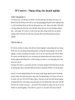
Optimizer Overview
The MicroSim PSpice Optimizer is a circuit optimization
program that improves the performance of analog and mixed
analog/digital circuits. The PSpice Optimizer is fully integrated
with other MicroSim programs. This means you can design your
circuit with MicroSim Schematics, simulate with MicroSim
PSpice A/D (or MicroSim PSpice), analyze results with
MicroSim Probe and optimize performance within the same
environment.
MODEL
+ BF =
packages
footprints
padstacks
symbols
packages
MicroSim
Schematics
MicroSim
PSpice
Optimizer
MicroSim
PSpice A/D
MicroSim
PCBoards
MicroSim
Probe
MicroSim
Parts
models
SPECCTRA
Autorouter
Gerber
files
drill
files
reports
How to Use this Guide
xv
How to Use this Guide
This guide is designed so you can quickly find the information
you need to use the PSpice Optimizer.
This guide assumes that you are familiar with Microsoft
Windows (NT or 95), including how to use icons, menus, and
dialog boxes. It also assumes you have a basic understanding
about how Windows manages applications and files to perform
routine tasks, such as starting applications and opening, and
saving your work. If you are new to Windows, please review
your Microsoft Windows User’s Guide.
Typographical Conventions
Before using the PSpice Optimizer, it is important to understand
the terms and typographical conventions used in this
documentation.
This guide generally follows the conventions used in the
Microsoft Windows 95 User’s Guide. Procedures for performing
an operation are generally numbered with the following
typographical conventions.
Notation Examples Description
ALL CAPS ANALOG.SLB or
CLIPPER.SCH
Library files and file names.
C
+
r
Press
C
+
r
A specific key or key stroke
on the keyboard.
monospace
font
Type
VAC
... Commands/text entered from
the keyboard.
Notation Examples Description
For UNIX users:
All screen captures in this
manual are of Windows 95
dialo
g boxes and windows.
Most options in these dialo
g
boxes and windows are
available in your operatin
g
environment. When certain
options are not available to you,
or you must do somethin
g
differently than what is primarily
outlined, information specific to
your platform is provided.
xvi Before You Begin
Related Documentation
Documentation for MicroSim products is available in both hard
copy and online. To access an online manual instantly, you can
select it from the Help menu in its respective program (for
example, access the Schematics User’s Guide from the Help
menu in Schematics).
Note
The documentation you receive depends on the
software confi
guration you have purchased.
The following table provides a brief description of those
manuals available in both hard copy and online.
This manual... Provides information about how to use...
MicroSim Schematics
User’s Guide
MicroSim Schematics, which is a schematic capture front-end program
with a direct interface to other MicroSim programs and options.
MicroSim PCBoards
User’s Guide
MicroSim PCBoards, which is a PCB layout editor that lets you specify
printed circuit board structure, as well as the components, metal, and
graphics required for fabrication.
MicroSim PSpice A/D & Basics+
User’s Guide
PSpice A/D, Probe, the Stimulus Editor, and the Parts utility, which are
circuit analysis programs that let you create, simulate, and test analog and
digital circuit designs. It provides examples on how to specify simulation
parameters, analyze simulation results, edit input signals, and create
models.
MicroSim PSpice & Basics
User’s Guide
MicroSim PSpice & MicroSim PSpice Basics, which are circuit analysis
programs that let you create, simulate, and test
analog-only circuit designs.
MicroSim PLSyn
User’s Guide
MicroSim PLSyn, which is a programmable logic synthesis program that
lets you synthesize PLDs and CPLDs from a schematic or hardware
description language.
MicroSim FPGA
User’s Guide
MicroSim FPGA—the interface between MicroSim Schematics and
XACTstep—with MicroSim PSpice A/D to enter designs that include
Xilinx field programmable gate array devices.
MicroSim Filter Designer
User’s Guide
MicroSim Filter Designer, which is a filter synthesis program that lets you
design electronic frequency selective filters.
If You Have the Evaluation Version
xvii
The following table provides a brief description of those
manuals available online only.
If You Have the
Evaluation Version
The evaluation version of the PSpice Optimizer has the
following requirements and limitations:
•
Requires the MicroSim PSpice A/D with Schematics
evaluation package.
•
Is limited to one goal, one parameter, and one constraint.
This online manual... Provides this...
MicroSim PSpice A/D
Online Reference Manual
Reference material for PSpice A/D. Also included: detailed descriptions of the
simulation controls and analysis specifications, start-up option definitions, and
a list of device types in the analog and digital model libraries. User interface
commands are provided to instruct you on each of the screen commands.
MicroSim Application Notes
Online Manual
A variety of articles that show you how a particular task can be accomplished
using MicroSim‘s products, and examples that demonstrate a new or different
approach to solving an engineering problem.
Online Library List A complete list of the analog and digital parts in the model and symbol
libraries.
MicroSim PCBoards Online
Reference Manual
Reference information for MicroSim PCBoards, such as: file name extensions,
padstack naming conventions and standards, footprint naming conventions, the
netlist file format, the layout file format, and library expansion and
compression utilities.
MicroSim PCBoards Autorouter
Online User’s Guide
Information on the integrated interface to Cooper & Chyan Technology’s
(CCT) SPECCTRA autorouter in MicroSim PCBoards.
Things You Need to Know
1
Chapter Overview
This chapter introduces the purpose and function of the PSpice
Optimizer, the optimization process, and related terms.
What is the PSpice Optimizer?
on page 1-2 describes optimizer
capabilities and the criteria designs must meet for successful
optimization.
Using the PSpice Optimizer with Other MicroSim Programs
on
page 1-4 presents the high-level design flow for optimization
and how other MicroSim programs are integrated into each
design phase.
Terms You Need to Understand
on page 1-5 defines the terms
that are important for optimizing designs successfully.
1
-
2 Things You Need to Know
What is the PSpice
Optimizer?
The MicroSim PSpice Optimizer is a circuit optimization
program that improves the performance of analog and mixed
analog/digital circuits.
Run optimizations
The PSpice Optimizer performs
iterative simulations, while adjusting the values of design
parameters until performance goals, subject to specified
constraints, are nearly or exactly met. Constraints can include
simple bounds on parameter values and nonlinear functions. The
PSpice Optimizer also computes Lagrange multipliers that
provide information on the cost of each constraint on the
solution.
Explore performance tradeoffs
When you enter new
values for design parameters, the PSpice Optimizer provides
graphical feedback showing performance. You can also tweak
goal and constraint values to examine changes to parameter
values.
Fit model parameters
Given a parameterized model, a
set of measured data points, and a good starting point for the
parameter values, the PSpice Optimizer fits a more accurate
model.
What is the PSpice Optimizer? 1
-3
Designs that You Can Optimize
A design that you can optimize must meet the following criteria:
•
It works; that is, it simulates with PSpice to completion and
behaves as intended.
•
One or more of its components have a variable value, and
each value that is varied relates to an intended performance
goal.
•
An algorithm exists to measure its performance as a
function of the variable value.
If you can visualize what factors should be adjusted to improve
performance, and how you would manually step through the
optimization process (even though the computations might seem
unwieldy), then the design is a good candidate for the PSpice
Optimizer.
Designs that You Cannot
Optimize
You cannot use the PSpice Optimizer to:
•
Create a working design. This especially applies when you
begin with a design that is far from meeting specifications.
•
Optimize a design in which the circuit has several states
where a small change in a parameter value causes a change
of state.
Example: A flip-flop is on for some parameter value, and off
for a slightly different value.
Optimization problems are not
always solvable by a particular
al
gorithm.
1
-
4 Things You Need to Know
Using the PSpice
Optimizer with Other
MicroSim Pro
grams
The PSpice Optimizer is fully integrated with other MicroSim
programs. This means you can design your circuit with
MicroSim Schematics, simulate with MicroSim PSpice A/D (or
MicroSim PSpice), analyze results with MicroSim Probe and
optimize performance within the same environment. Figure 1-1
illustrates the typical design flow for circuit optimization.
Fi
gure 1-1
Optimization Design Flow
Because you can use
Schematics, PSpice, and Probe
to desi
gn and simulate at the
system, subcircuit, or component
level, use the PSpice Optimizer
to optimize at whatever level is
most appropriate.
MicroSim
Schematics
MicroSim
PSpice A/D
MicroSim
Probe
MicroSim
PSpice
Optimizer
MicroSim
Schematics
MicroSim
PSpice A/D
MicroSim
PSpice
Optimizer
MicroSim
PSpice A/D
Develop
the
Design
Set Up
the
Optimization
Run
the
Optimization
Fit
Model
Parameters
Phase One
Phase Two
Phase Three
See Chapter 2, “
Primer: How to
Optimize a Design
” for a detailed
description of each desi
gn
phase.
Terms You Need to Understand 1
-5
Terms You Need to
Understand
Optimization
Optimization is the process of fine-tuning a
design by varying design parameters between successive
simulations until performance comes close to (or exactly meets) the
ideal performance.
The PSpice Optimizer solves four types of optimization problems
as described in Table 1-1.
*. All four cases allow simple bound constraints; that is, lower and upper bounds on all of
the parameters. The PSpice Optimizer also handles nonlinear goals and constraints.
**. Use unconstrained least squares when fitting model parameters to a set of
measurements, or when minimizing more than one goal.
Table 1-1
Optimization Problems
*
Problem Type PSpice Optimizer Action Example
unconstrained minimization reduces the value of a single goal minimize the propagation delay
through a logic cell
constrained minimization reduces the value of a single goal while
satisfying one or more constraints
minimize the propagation delay
through a logic cell while keeping the
power consumption of the cell less than
a specified value
unconstrained least squares
**
reduces the sum of the squares of the
individual errors (difference between
the ideal and the measured value) for a
set of goals
given a terminator design, minimize
the sum of squares of the errors in
output voltage and equivalent
resistance
constrained least squares reduces the sum of squares of the
individual errors for a set of goals
while satisfying one or more
constraints
minimize the sum of squares of the
figures of merit for an amplifier design
while keeping the open loop gain equal
to a specified value
1
-
6 Things You Need to Know
Parameter
A parameter defines a property of the design for
which the PSpice Optimizer attempts to determine the best value
within specified limits. A parameter can:
•
Represent component values (such as resistance, R, for
a resistor).
•
Represent other component attribute values (such as
slider settings in a potentiometer).
•
Participate in expressions used to define component
values or other component attribute values.
The PSpice Optimizer can optimize designs with up to eight
variable parameters.
Example: A potentiometer symbol in a schematic uses the SET
attribute to represent the slider position. You can assign a
parameterized expression to this attribute to represent variable
slider positions between 1 and 0. During optimization, the
PSpice Optimizer varies the parameterized value of the SET
attribute.
Specification
A specification describes the ideal behavior
of a design in terms of goals and constraints.
Examples: For a given design, the gain shall be 20 dB ±1 dB; for
a given design, the 3 dB bandwidth shall be 1 kHz; for a given
design, the rise time must be less than 1 usec.
A design can have up to eight goals and constraints in any
combination, but there must always be at least one goal. You can
easily change a goal to a constraint and vice-versa.
The PSpice Optimizer accepts specifications in two formats:
internal and external.
Internal specifications
An internal specification is composed of goals and constraints
defined in terms of target values and ranges, which are entered
into the PSpice Optimizer through dialog boxes.
See
Chapter 6,Tutorial:
Exploring Design Tradeoffs
(Active Filter)
starting on page
6-1
for a working example
showin
g parameterized slider
values.
For more information, see
Goal
and
Constraint on page 1-8
.
Terms You Need to Understand 1
-7
External specifications
An external specification is composed of measurement data,
which are defined in an external data file that is read by the
PSpice Optimizer.
Target value
A target value is the ideal operating value for
a characteristic of the design as defined by a goal or constraint
specification.
Goal
A goal defines the performance level that the design
should attempt to meet (e.g., minimum power consumption). A
goal specification includes:
•
The name of the goal.
•
A target value and an acceptable range.
•
A circuit file to simulate.
•
An evaluation for measuring performance.
•
An analysis type used for simulation-based evaluations.
The goal specification can also include:
•
The name of the file containing Probe goal function
definitions (.prb file).
•
When using an external specification, the name of the file
containing measured data and the columns of data to be used
as reference.
Note
Typically, the PSpice
Optimizer measures
performance usin
g an
evaluation that requires a
simulation, and therefore, you
must specify the circuit file for
the simulation. However,
when measurin
g performance
usin
g PSpice Optimizer
expressions which do not
require a simulation, you do
not need to specify a circuit
file.
1
-
8 Things You Need to Know
Constraint
A constraint defines the performance level that
the design must fulfill in which the target value exceeds, falls
below, or equals a specified value (e.g., an output voltage that
must be greater than a specific level). The constraint
specification includes:
•
The name of the constraint.
•
A target value and an acceptable range.
•
A circuit file to simulate. (See note on previous page.)
•
An evaluation for measuring performance.
•
An analysis type used for simulation-based evaluations.
•
An allowed relationship between measured values and the
target value, which can be one of the following:
The constraint specification can also include the name of the file
containing Probe goal function definitions (.prb file).
Constraints are often nonlinear functions of the parameters in
the design.
Example: Bandwidth can vary as the square root of a bias
current and as the reciprocal of a transistor dimension.
Performance
The performance of a design is a measure of
how closely its specifications’ calculated values approach their
target values for a given set of parameter values. When there are
multiple specifications (at least one of which is a goal), the
PSpice Optimizer uses the sum of the squares of their deviations
from target to measure closeness. For a single specification
(goal), the PSpice Optimizer uses either the goal’s value, or the
square of its deviation from target.
<= measured value must be less than or equal
to the target value
= measured value must equal the target value
>= measured value must be greater than or
equal to the target value
See
Optimization on page 1-5
for more on least-squares and
minimization al
gorithms.
Terms You Need to Understand 1
-9
Each aspect of a design’s performance is found by either:
•
first performing the appropriate simulation, then running
Probe to measure characteristics of the resulting
waveform(s), or
•
evaluating PSpice Optimizer expressions.
In many cases (particularly if there are multiple conflicting
specifications), it is possible that the PSpice Optimizer will not
meet all of the goals and constraints. In these cases, optimum
performance is the best compromise solution—that is, the
solution that comes closest to satisfying each of the goals and
constraints, even though it may not completely satisfy any single
one.
Evaluation
An evaluation is an algorithm that computes a
single numerical value, which is used as the measure of
performance with respect to a design specification.
The PSpice Optimizer accepts evaluations in one of these three
forms:
•
single-point Probe trace function
•
Probe goal function
•
PSpice Optimizer expression
Given evaluation results, the PSpice Optimizer determines
whether or not the changes in parameter values are improving
performance, and determines how to select the parameters for
the next iteration.
Trace function
A trace function defines how to evaluate a
design characteristic when running a single-point analysis (such
as a DC sweep with a fixed voltage input of 5 V).
Examples: V(out) to measure the output voltage; I(d1) to
measure the current through a component.
Refer to the online
MicroSim
PSpice A/D Reference Manual
for the variable formats and
mathematical functions you can
use to specify a trace function.
1
-
10 Things You Need to Know
Probe goal function
A Probe goal function defines how
to evaluate a design characteristic when running any kind of
analysis other than a single-point sweep analysis. A goal
function computes a single number from a Probe waveform.
This can be done by finding a characteristic point (e.g., time of
a zero-crossing) or by some other operation (e.g., RMS value of
the waveform).
For example, you can use Probe goal functions to:
•
Find maxima and minima in a trace.
•
Find distance between two characteristic points (such as
peaks).
•
Measure slope of a line segment.
•
Derive aspects of the circuit’s performance which are
mathematically described (such as 3 dB bandwidth, power
consumption, and gain and phase margin).
To write effective goal functions, determine what you are
attempting to measure, then define what is mathematically
special about that point (or set of points).
Note
Be sure that the goal functions accurately measure
what they are intended to measure. Optimization
results hi
ghly depend on how well the goal
functions behave. Discontinuities in
goal functions
(i.e., sudden jumps for small parameter chan
ges)
can cause the optimization process to fail.
PSpice Optimizer expression
A PSpice Optimizer
expression defines a design characteristic. The expression is
composed of optimizer parameter values, constants, and the
operators and functions shown in Table 1-2.
Example: To measure the sum of resistor values for two resistors
with parameterized values named R1val and R2val,
respectively, use the PSpice Optimizer expression R1val +
R2val.
Refer to the Goal Function
wizard in Probe
and your PSpice
user’s
guide for information on
how to develop and specify
goal
functions.
Here are some quick tips. In
Probe:
• To test the value returned by
a specified
goal function,
select Eval Goal Function
from the Trace menu.
• To see the waveforms and
marked points used to
evaluate a
goal function,
select Display Evaluation in
the Probe Options dialo
g box
(from the Tools menu, select
Options to display this dialo
g
box).
See
Gain on page 7-5
for an
example of the YatX
goal
function definition.