Electromagnetics for high speed analog and digital communication circuits
Bạn đang xem bản rút gọn của tài liệu. Xem và tải ngay bản đầy đủ của tài liệu tại đây (4.97 MB, 467 trang )
www.IrPDF.com
www.elsolucionario.net
www.IrPDF.com
www.elsolucionario.net
This page intentionally left blank
www.IrPDF.com
www.elsolucionario.net
Electromagnetics for High-Speed Analog and
Digital Communication Circuits
Modern communications technology demands smaller, faster, and more efficient circuits, the
design of which requires a good understanding of circuit theory and electromagnetics. This
book reviews the fundamentals of electromagnetism as applied to passive and active circuit
elements, highlighting the various effects and potential problems in designing a new circuit.
The author begins with a review of the basics: the origin of resistance, capacitance, and
inductance, from a circuit and field perspective; then progresses to more advanced topics
such as passive device design and layout, resonant circuits, impedance matching, highspeed switching circuits, and parasitic coupling and isolation techniques. Using examples
and applications in RF and microwave systems, the author describes transmission lines,
transformers, and distributed circuits. State-of-the-art developments in Si-based broadband
analog, RF, microwave, and mm-wave circuits are also covered. With up-to-date results,
techniques, practical examples, many illustrations, and worked examples, this book will
be valuable to advanced undergraduate and graduate students of electrical engineering
and practitioners in the IC design industry. Further resources for this title are available at
www.cambridge.org/9780521853507.
a l i m. ni k n e j a d obtained his Ph.D. in 2000 from the University of California, Berkeley,
where he is currently an associate professor in the EECS department. He is a faculty director
at the Berkeley Wireless Research Center (BWRC) and the co-director of the BSIM Research
Group. Before his appointment at Berkeley, Niknejad worked for several years in industry
designing CMOS and SiGe ICs. He has also served as an associate editor of the IEEE Journal
of Solid-State Circuits, and was a co-recipient of the Jack Raper Award for Outstanding
Technology Directions Paper at ISSCC 2004.
www.IrPDF.com
www.elsolucionario.net
www.IrPDF.com
www.elsolucionario.net
Electromagnetics for
High-Speed Analog and Digital
Communication Circuits
ALI M. N I K N EJ A D
www.IrPDF.com
www.elsolucionario.net
CAMBRIDGE UNIVERSITY PRESS
Cambridge, New York, Melbourne, Madrid, Cape Town, Singapore, São Paulo
Cambridge University Press
The Edinburgh Building, Cambridge CB2 8RU, UK
Published in the United States of America by Cambridge University Press, New York
www.cambridge.org
Information on this title: www.cambridge.org/9780521853507
© Cambridge University Press 2007
This publication is in copyright. Subject to statutory exception and to the provision of
relevant collective licensing agreements, no reproduction of any part may take place
without the written permission of Cambridge University Press.
First published in print format 2007
ISBN-13
ISBN-10
978-0-511-27009-3 eBook (NetLibrary)
0-511-27009-7 eBook (NetLibrary)
ISBN-13
ISBN-10
978-0-521-85350-7 hardback
0-521-85350-8 hardback
Cambridge University Press has no responsibility for the persistence or accuracy of urls
for external or third-party internet websites referred to in this publication, and does not
guarantee that any content on such websites is, or will remain, accurate or appropriate.
www.IrPDF.com
www.elsolucionario.net
Contents
Preface
Acknowledgments
page ix
xi
1
Introduction
1.1 Motivation
1.2 System in Package (SiP): chip and package co-design
1.3 Future wireless communication systems
1.4 Circuits and electromagnetic simulation
1
1
13
13
15
2
Capacitance
2.1 Electrostatics review
2.2 Capacitance
2.3 Non-linear capacitance
2.4 References
18
18
32
41
52
3
Resistance
3.1 Ohm’s Law
3.2 Conduction in semiconductors
3.3 Diffusion
3.4 Thermal noise
3.5 References
53
53
59
66
68
73
4
Amp`ere, Faraday, and Maxwell
4.1 Amp`ere: static magnetic fields
4.2 Magnetic materials
4.3 Faraday’s big discovery
4.4 Maxwell’s displacement current
4.5 References
74
74
82
88
91
95
5
Inductance
5.1 Introduction
5.2 Inductance
5.3 Magnetic energy and inductance
5.4 Discussion of inductance
96
96
97
101
106
v
www.IrPDF.com
vi
Contents
5.5
5.6
5.7
5.8
5.9
5.10
5.11
www.elsolucionario.net
Partial inductance and return currents
Impedance and quality factor
Frequency response of inductors
Quality factor of inductors
Inductors and switching circuits
Preview: how inductors mutate into capacitors
References
119
120
121
130
133
135
136
6
Passive device design and layout
6.1
Ring inductor
6.2
The classic coil
6.3
Spirals
6.4
Symmetric inductors
6.5
Multilayer inductors
6.6
Inductor equivalent circuit models
6.7
Integrated capacitors
6.8
Calculation by means of the vector potential
6.9
References
6.10 Appendix: Filamental partial mutual inductance
137
137
141
143
145
147
149
150
153
165
165
7
Resonance and impedance matching
7.1
Resonance
7.2
The many faces of Q
7.3
Impedance matching
7.4
Distributed matching networks
7.5
Filters
7.6
References
168
168
180
186
199
199
200
8
Small-signal high-speed amplifiers
8.1
Broadband amplifiers
8.2
Classical two-port amplifier design
8.3
Transistor figures of merit
8.4
References
201
202
220
242
244
9
Transmission lines
9.1
Distributed properties of a cable
9.2
An infinite ladder network
9.3
Transmission lines as distributed ladder networks
9.4
Transmission line termination
9.5
Lossless transmission lines
9.6
Lossy transmission lines
9.7
Field theory of transmission lines
9.8
T-line structures
9.9
Transmission line circuits
246
246
248
249
253
255
260
264
265
272
www.IrPDF.com
Contents
9.10
9.11
9.12
www.elsolucionario.net
The Smith Chart
Transmission line-matching networks
References
vii
282
287
292
10
Transformers
10.1
Ideal transformers
10.2
Dot convention
10.3
Coupled inductors as transformers
10.4
Coupled inductor equivalent circuits
10.5
Transformer design and layout
10.6
Baluns
10.7
Hybrid transformer
10.8
Transformer parasitics
10.9
Transformer figures of merit
10.10 Circuits with transformers
10.11 References
293
293
294
295
296
299
301
302
305
305
310
319
11
Distributed circuits
11.1
Distributed RC circuits
11.2
Transmission line transformers
11.3
FETs at high frequency
11.4
Distributed amplifier
11.5
References
320
320
325
332
335
342
12
High-speed switching circuits
12.1
Transmission lines and high-speed switching circuits
12.2
Transients on transmission lines
12.3
Step function excitation of an infinite line
12.4
Terminated transmission line
12.5
Reactive terminations
12.6
Transmission line dispersion
12.7
References
343
343
345
346
348
357
360
363
13
Magnetic and electrical coupling and isolation
13.1
Electrical coupling
13.2
Magnetic coupling
13.3
Ground noise coupling
13.4
Substrate coupling
13.5
Package coupling
13.6
References
364
364
367
373
378
383
385
14
Electromagnetic propagation and radiation
14.1
Maxwell’s equations in source-free regions
14.2
Penetration of waves into conductors
386
386
390
www.IrPDF.com
viii
Contents
14.3
14.4
14.5
14.6
14.7
14.8
15
www.elsolucionario.net
Poynting vector
EM power carried by a plane wave
Complex Poynting Theorem
Reflections from a perfect conductor
Normal incidence on a dielectric
References
395
397
399
402
404
406
Microwave circuits
15.1 What are microwave circuits?
15.2 Microwave networks
15.3 Lorentz reciprocity theorem
15.4 The network formulation
15.5 Scattering matrix
15.6 Properties of three-ports
15.7 Properties of four-ports
15.8 Two conductor coupler
15.9 References
407
407
409
409
412
414
421
429
438
440
References
Index
441
445
www.IrPDF.com
www.elsolucionario.net
Preface
Why another EM book? There are virtually thousands of books written on this subject and
yet I felt the urge to write another one.
The idea for this book germinated in my mind on a long and uneventful drive from
Berkeley to San Diego. I had just completed my first year of graduate school at Berkeley
and had started a research project on analyzing spiral inductors. It occurred to me that
studying electromagnetics as a circuit designer was a lot easier than studying it as an
undergraduate at UCLA. Even though I took many EM courses during my undergraduate
education, very little of it actually stuck with me. Much like all those foreign languages
we learn in high school or college, without any practice, we quickly lose our skills. When we
find ourselves at that critical moment in a foreign country, our language skills fail us. While
EM is the foundation of much of electrical engineering, somehow it’s treated as a foreign
tongue, spoken only by the few learned folks in the the field. But learning EM should not
be like learning Greek or Latin!
That summer I spent many weekends in San Diego visiting my family. During these trips
I’d take my EM books down to the beach and study. I’d plant myself on the beach at La Jolla
or Del Mar and work my way through my undergraduate EM text. This time around, things
were making a lot more sense, since I had an urgent need to actually learn electromagnetics.
But I observed that having a circuits background was somewhat equivalent to speaking a
related derived tongue. I realized that many people out there also missed the boat on learning
EM, since they learned it without any background, desire, or need to learn it. But many of
those same people, after taking a lot of high-frequency electronics courses, feel they need
to relearn this important subject. If you’re one of those people, this book is written for you!
When I was an undergraduate student, EM courses were a required part of every EE
student’s education. No matter how painful, you had to work your way through two or three
courses. But today the situation has changed dramatically. Many schools have made this
an optional course and, much to our horror, many students simply skip it! Even though
they do take EM as part of their physics education, the emphasis is on fundamentals, with
no coverage of important engineering topics such as transmission lines or waveguides.
Today, more than ever, this seems like a tragedy. High-speed digital, RF, and microwave
circuits abound, necessitating the training of engineers in the art and science of electronics,
electromagnetics, communication circuits, antennas, propagation, etc.
With the availability of high-speed 64-bit microprocessors, server farms, Gb/s networks,
and mass storage, many practical problems are now computationally tractable. Workers in
the field of high-speed electronics are increasingly turning to commercial electromagnetic
ix
www.IrPDF.com
x
Preface
www.elsolucionario.net
solvers to tackle difficult problems. As powerful as EM solvers are today, it still takes a lot
of skill to set up and run a problem. And at the end of a long five hour simulation, can you
trust the results? Did you actually set up the problem correctly? Are the boundary conditions
appropriate? Is the field accuracy high enough? These are difficult questions and can only
be answered by observing the currents, voltages, and electric and magnetic fields with a
trained eye.
The focus of this book is the application of electromagnetics to circuit design. In contrast
to classical analog integrated circuit design, passive components play an integral role in the
design of RF, microwave, and broadband systems. Most books dedicate a section or at best
a chapter to this all important topic.
The book begins with the fundamentals – the origins of resistance, capacitance, and
inductance. We spend a great deal of time reviewing these fundamental passive elements
from a circuit and field perspective. With this solid foundation, the book progresses to
more advanced applications. A chapter on passive device design and layout reviews stateof-the-art layout techniques for the realization of passive devices in an integrated circuit
environment. Important circuit applications such as resonant circuits and impedance matching are covered extensively with an emphasis on the inner workings of the circuitry (rather
than a cookbook approach) in order to uncover important insights into the insertion loss
of these circuits. Next, the book moves to active two-port circuits and reviews the codesign of amplifiers with passive components. Two-port circuit theory is used extensively
to understand optimal power gain, stability, activity, and unilateral gain. Transmission lines,
transformers, and distributed circuits form the core of the advanced circuit applications
of passive elements. These topics are taught in a coherent fashion with many important
examples and applications to RF and microwave systems. The time-domain perspective is
covered in a chapter on high-speed switching circuits, with a detailed discussion of the transient waveforms on transmission lines and transmission line dispersion. Parasitic coupling
and isolation techniques are the topic of an entire chapter, including discussion of package, board, and substrate coupling. An introduction to the analysis and design of passive
microwave circuits is also covered, serving as a bridge to an advanced microwave textbook.
www.IrPDF.com
www.elsolucionario.net
Acknowledgments
I would like to thank all the people who have helped me write this book. Much of this
material was inspired by teaching courses at Berkeley and so I thank all the students who
read the original lecture notes and provided feedback in EECS 105, 117, 142, 217, and 242
(thanks to Ke Lu for detailed feedback). This book would not be as interesting (assuming you
find it so) without real circuit applications drawn from literature and from our own research
projects. Thanks to my colleagues and collaborators at Berkeley who have created a rich and
stimulating research environment. In particular, thanks to my BWRC colleagues, Robert
Brodersen, Jan Rabaey, Bora Nikolic, Robert Meyer, Paul Wright, and John Wawrzynek.
And thanks to Professor Chenming Hu for inviting me to be a part of the world-famous
BSIM team. Thanks to Jane Xi for her hard work and dedication to the BSIM team. Special
thanks goes to the graduate student researchers. In particular, thanks to Sohrab Emami and
Chinh Doan who were key players in starting the Berkeley 60 GHz project and OGRE.
Many of the high-frequency examples come from our experience with this project. Thanks
to Professor Andrea Bevilacqua (University of Padova, Italy) for a stimulating research
collaboration on UWB. Thanks to Axel Berny and his love of oscillators.
Though I take responsibility for any errors in the book, I have my graduate students to
thank for the countless errors they were able to find by reading through early drafts of the
manuscript. Thanks to Ehsan Adabi, Bagher (Ali) Afshar, Mounir Bohsali, Yuen Hui Chee,
Wei-Hung Chen, Debo Chowdhury, Mohan Dunga, Gang Liu, Peter Haldi, Babak Heydari,
and Nuntachai Poobuapheun. They provided detailed feedback on various chapters of the
book.
Also thanks to my friends and colleagues for reviewing the book. In particular I’m
grateful to Dr. Manolis Terrovitis, Eric Hoffman, Professor Hui Wu, and Professor Hossein
Hashemi for taking the time to review the book and provide feedback.
Finally, thanks to the folks who supported our research during the past four years. Special thanks to DARPA and the TEAM project, in particular thanks to Barry Perlman and
Dan Radack for your support of university research. Thanks to BWRC member companies, in particular ST Microelectronics, Agilent Technologies, Infineon, Conexant Systems,
Cadence, and Qualcomm. Thanks to Analog Devices, Broadcom, Berkeley Design Automation, and National Semiconductor for your support through the UC MICRO and UC Discovery programs. And thanks to SRC and member companies for supporting research of
compact modeling at Berkeley. Thanks in particular to Jim Hutchby of SRC, Keith Green
of Texas Instruments, Weidong Liu of Synopsys, Judy An of AMD, Josef Watts and Jack
Pekarik of IBM, and Ben Gu of Freescale.
xi
www.IrPDF.com
www.elsolucionario.net
www.IrPDF.com
www.elsolucionario.net
1 Introduction
1.1
Motivation
The history of electronics has been inextricably linked with the growth of the communications industry. Electronic communication served as a major enabling technology for
the industrial revolution. When scientists and engineers learned to control electricity and
magnetism, it did not take long for people to realize that the electromagnetic force would
enable long-range communication. Even though the basic science of Maxwell’s equations
was well understood, it took much longer for practical applications to fully exploit all the
fantastic possibilities such as radio, television, and personal wireless communication.
At first only crude wires carrying telegraph signals were rolled out sending Morse code,1
digital signals at speeds limited by human operators. In this regard it is ironic that digital
communication predates analog communication. Telegraph wires were laid alongside train
tracks, making long-range communication and transportation a practical reality. Sending
signals faster and further ignited the imagination of engineers of the time and forced them
to study carefully and understand the electromagnetic force of nature. Today we are again
re-learning and inventing new digital and analog communication systems that are once again
compelling us to return to the very fundamental science of electricity and magnetism.
The topic of this book is the high-frequency electromagnetic properties of passive and
active devices. For the most part, passive devices are resistors, capacitors, transformers,
and inductors, while active devices are transistors. Most applications we draw from are
high-frequency circuits. For example, radio frequency (RF) circuits and high-speed digital
circuits both depend on a firm understanding of passive devices and the environment in
which they operate.
Circuit theory developed as an abstraction to electromagnetics. Circuit theory is in effect
the limit of electromagnetics for a circuit with negligible dimension. This allows spatial
variations and time delay to be ignored in the analysis of the circuit. As such, it allowed
practicing engineers to forego solving Maxwell’s equations and replaced them with simple
concepts such as KCL and KVL. Even differential equations were eliminated and replaced
with algebraic equations by employing Laplace transforms. The power and popularity of
circuit theory was due to its simplicity and abstraction. It allowed generations of engineers to
1
Or as Paul Nahin suggests in [41] we should more correctly call this “Vail” code.
1
www.IrPDF.com
2
1 Introduction
www.elsolucionario.net
solve difficult problems with simple and yet powerful tools. In effect, it allowed generations
of engineers to forego reading a book such as this one.
So why read another book on electromagnetics? Why bother learning all this seemingly
complicated theory when your ultimate goal is to build circuits and systems for communication and information management?
We live today at the intersection of several interesting technologies and applications.
Integrated circuit technology has enabled active devices to operate at increasingly higher
frequencies, turning low-cost Si technology into a seemingly universal panacea for a wide
array of applications. CMOS digital circuits are switching at increasingly higher rates,
pushing multi GHz operation. Si CMOS, bipolar, and SiGe technology have also enabled
a new class of low-cost RF and microwave devices, with ubiquitous deployment of cellular
phones in the 800 MHz–2 GHz spectrum, and high-speed wireless LAN in the 2–5 GHz
bands. There seems to be very little in the way of enabling Si technology to exploit the
bandwidths up to the limits of the device technology. In a present-day digital 130 nm
CMOS process, for instance, circuits are viable up to 60 GHz [55] [13].
At the same time, wired communication is pushing the limits. Gigabit Ethernet and highspeed USB cables are now an everyday reality, and people are already pursuing a 10 Gb/s
solution. Optical communication is of course at the forefront, with data rates in the 40 Gb/s
range now commercially viable and at relatively low cost.
The simultaneous improvement in active device technology, miniaturization, and a host
of new applications are the driving force of today’s engineering. As integrated circuits
encompass more functionality, many traditionally off-chip components are pushed into the
IC or package, blurring the line between active devices and circuits and passive devices and
electromagnetics. This is the topic of this book.
Technology enhancements
The limitations in frequency and thus speed of operation is usually set by the active device
technology. One common figure of merit for a technology is, f r , the unity-gain frequency
f T , the frequency at which the short-circuit current gain of the device crosses unity. Another
important figure of merit is f max the maximum frequency of oscillation, or equivalently the
frequency where the maximum power gain of a transistor drops to unity. Since f max is a
strong function of layout and parasitics in a process, it is less often employed. In contrast,
the f T depends mostly on the dimensions of the transistor and the transconductance
fT =
gm
1
2π Cπ + Cµ
(1.1)
It can be shown [50] that the device f T is inversely related to the transistor dimensions.
For a long-channel MOSFET the key scaling parameter is the channel length L
fT ≈
1 3µ(Vgs − Vt )
2π
2L 2
(1.2)
www.IrPDF.com
www.elsolucionario.net
1.1 Motivation
3
100
gion
el re
nn
-cha
rt
sho
10
fT
1
0
1980
lon
c
g-
ha
1985
nn
r
el
eg
ion
1990
1995
2000
2005
year
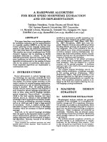
Figure 1.1 The improvements in device unity–gain frequency f T over the past two decades due to
device scaling.
while in the limit for short channel transistors the scaling changes to L −1 since the current
is limited by velocity saturation
Ids,sat = W Q i vsat = W Cox (Vgs − Vt )vsat
(1.3)
resulting in
vsat
(1.4)
L
For a bipolar junction transistor (BJT) the critical dimension is the base width. In the limit
that base transit limits the frequency of operation
fT ∝
fT ≈
1 1
1
∝ 2
2π τ B
WB
(1.5)
As integrated circuit manufacturing technology has improved exponentially in the past three
decades, so has the f T of the device, giving circuit designers increasingly faster devices.
A plot of the device f T over the years for a MOSFET device is shown in Fig. 1.1, and the
exponential growth in technological advancements can be seen clearly.
It is important to note that this improvement in performance only applies to the intrinsic
device. Early circuits were in fact limited by the intrinsic transistor and not the parasitic
routing and off-chip environment. As circuit technology has advanced, though, the situation
has reversed and now the limitation is set by the parasitics of the chip and board environment,
as well as the performance of the passive devices. This is why the material of this book is
now particularly relevant. It can be shown that a good approximation to the CMOS device
f max is given by [42]
f max ≈
fT
2 Rg (gm C gd /C gg ) + (Rg + rch + Rs )gds
(1.6)
www.IrPDF.com
4
www.elsolucionario.net
1 Introduction
thick metal
MIM Capacitor
vias
metal
p-well
NMOS
n-well
PMOS
n+
base
col
SiGe Bipolar
p-sub
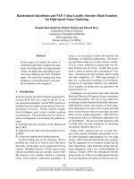
Figure 1.2 Cross section of a SiGe BiCMOS process.
thick metal
vias
p-well
NMOS
n-well
PMOS
n+
metal
p+
NMOS
(not isolated)
p-sub
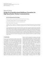
Figure 1.3 Cross section of an advanced CMOS process.
where the device performance is a strong function of the loss, such as the drain/source
resistance Rs , Rd , and the gate resistance Rg . These parasitics are in large part determined
by layout and the process technology.
While early integrated circuit technologies were limited to a few types of different active
devices and a few layers of aluminum interconnect metal, present-day process technology has a rich array of devices and metal routing. In an advanced Si process, shown in
Fig. 1.2, high-performance SiGe HBT devices are complemented by MOS and PN-junction
varactors, metal-insulator-metal (MIM) high-density and high-quality capacitors, and thickmetal for low-loss interconnect and inductors/transformers. Even a digital CMOS process,
as shown in Fig. 1.3, has many advanced capabilities. In addition to several flavors of MOS
active devices (fast thin oxide, thick oxide, high/low VT ), there are also enhanced isolation
structures and triple-well (deep n-well) devices, and many layers of interconnect that allow
construction of high-quality, high-density capacitors and reasonably high-quality inductors.
www.IrPDF.com
1.1 Motivation
www.elsolucionario.net
RF
Ra
5
dia
tion
Audio Waves
(a)
(b)
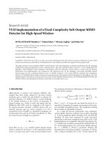
Figure 1.4 (a) A simple AM receiver circuit. The resistor represents a high-input impedance earphone.
(b) A physical realization of the simple AM receiver circuit.
Radio and wireless communication
Early radio systems were essentially all passive. To see this look into the back of an old radio
where a few active devices (vacuum tubes or transistors) are surrounded by tens to hundreds
of passive devices. Consider the circuit diagram of a very simple AM receiver shown in
Fig. 1.4a. The antenna drives a resonant tank tuned to the center frequency of the transmitting
station. This signal is fed into a peak detector that follows the peak of the RF signal. The
low-pass filter time constant is only fast enough to follow the low-frequency audio signal
(generically the baseband signal) and yet too slow to follow the RF, thus removing the RF
signal and retaining the low-frequency audio. This received signal is usually too weak to
drive a speaker but can be heard through a sensitive headphone. A simple audio amplifier
can be used to strengthen the signal.
It is interesting to note that this AM receiver can be physically realized by merely using
contacts between a few different pieces of metal and semiconductors. This is shown in
Fig. 1.4b. The resonant tank is simply a piece of wire wound into a coil which contacts with
the capacitor, two metal plates in close proximity. The diode can be realized as the junction
of a metal and semiconductor. Finally, to convert electric energy into sound we can use
another large inductor coil and use the time-varying magnetic force to move a paper thin
cone driven by a magnetic core. Magnetic materials have been known since ancient times
and therefore since the metal age we have had the capability to build radio receivers! In
fact, it is not surprising that radios often crop up accidentally.2
Most modern radios operate based on an architecture invented by Edwin Armstrong. The
block diagram of such a system, called a super-heterodyne receiver, is shown in Fig. 1.7.
This receiver incorporates a local oscillator (LO), a block that primarily converts DC power
into RF power at the oscillation frequency. A mixer takes the product of this signal and the
2
For instance my old answering machine also picked up the radio. Sometimes you could hear it as you were waiting
for the tape recorder to rewind. At least this was a desirable parasitic radio.
www.IrPDF.com
6
1 Introduction
www.elsolucionario.net
signal received by the antenna. Recall the following trigonometric identity3
2 cos(ω L0 t) cos(ω R F t) = cos((ω L0 + ω R F )t) + cos((ω L0 − ω R F )t)
(1.7)
Note that the product of the received RF signal and the local oscillator signal produces
two new signals, one centered at the difference frequency and one centered at the sum
frequency. If we put a bandpass filter at one of these frequencies, call it the intermediate
frequency, IF, we can electronically tune the radio by simply changing the LO frequency.
This is accomplished by using a frequency synthesizer (a PLL or phase locked loop), and
thus we avoid building a variable filter common to the early radios. The important point is
that the IF is fixed and we can build a very selective filter to pinpoint our desired signal and
to reject everything else. Why not simply set LO equal to RF to move everything to DC?
This is in fact the direct-conversion or zero-IF architecture. It has some shortcomings such
as problems with DC offset,4 but its main advantage is that it lowers the complexity of the
RF section of a typical radio.
At the heart of the frequency synthesizer is the voltage controlled oscillator (VCO).
The VCO is an oscillator where the output frequency is a function of a control voltage
or current.5 To build a VCO we need a way to change the center frequency of a resonant
tank. The resonant tank is simply an inductor in series or in parallel with a capacitor. One
typical realization is to use varactor, a variable capacitor. A reversed biased diode serves
this purpose nicely, as the depletion region width, and thus the small-signal capacitance, is
a function of the reverse bias. It seems that a super-heterodyne receiver has simply moved
the variable resonant tank from the antenna front end to a variable resonant tank in the
VCO! Have we gained anything? Yes, because the frequency of the VCO can be controlled
precisely in a feedback loop (using an accurate frequency reference such as a crystal),
eliminating any problems associated with absolute tolerances in components in addition to
drift and temperature variation.
The radio has once again emerged as a critical application of passive devices spawned by
the growth and popularity of wireless telephones, in particular the cellular phone. By limiting
the transmitter powers and taking advantage of spatial diversity (re-using the same frequency
band for communication for points far removed – for non-adjacent cell sites), a few hundred
radio channels can be used to provide wireless communication to millions of people. Modern
cell phones employ complicated radio receivers and transmitters (transceivers) employing
hundreds and thousands of passive devices. Early cell phones used simple architectures
such as the super-heterodyne receiver but the demand for low-cost and small footprints has
prompted a re-investigation of radio architectures.
The layout of a modern 2.4 GHz transceivers for 802.11b wireless LAN (WLAN) is
shown in Fig. 1.5 [7]. The IC is implemented in a 0.25 µ CMOS process and employs
several integrated passive devices such as spiral inductors, capacitors, and resistors. The
spiral inductors comprise a large fraction of the chip area. The next chip shown in Fig. 1.6
3
4
5
I recall asking my trig teacher about the practical application of the subject. After scratching her head and pondering
the question, her response was that architects use trig to estimate the height of buildings! A much better answer
would have been this equation.
And 1/ f noise in MOS technology.
This makes a nice AM to FM modulator, as well.
www.IrPDF.com
1.1 Motivation
www.elsolucionario.net
7
Figure 1.5 A 2.4 GHz CMOS 802.11b Wireless LAN Transceiver [7]. (Copyright 2003, IEEE)
Figure 1.6 A direct-conversion satellite broadband tuner-demodulator SOC [17] operates from 1–
2 GHz. (Copyright 2003, IEEE)
www.IrPDF.com
8
1 Introduction
www.elsolucionario.net
PLL
PA
VCO
Dr
IF
Analog IF and Digital Baseband
VGA
LNA
Figure 1.7 The block diagram of an Armstrong super-heterodyne transceiver.
[17] is an integrated direct-conversion satellite broadband tuner-demodulator “system-ona-chip” (SOC). The chip is implemented in a 0.18 µ CMOS process and employs MIM
capacitors and spiral inductors. It operates in the 1–2 GHz band, requiring broadband
operation and high linearity. Notice that the digital baseband has been integrated on to
a single chip along with the sensitive analog and RF blocks. This brings about several
important challenges in the design due to the parasitic coupling between the various blocks.
A triple-well process and lead-less package technology are used to maximize the isolation.
In general, integrating an entire transceiver on to a single chip has many challenges. The
power amplifier (PA) or PA driver can injection lock the VCO through the package and
substrate, causing a spurious modulation. Digital circuitry can couple seemingly random
switching signals into the analog path, effectively increasing the noise floor of the sensitive
RF and analog blocks. As the level of integration increases, a single chip or package may
contain several systems in operation simultaneously, requiring further understanding and
modeling of the coupling mechanisms.
Computers and data communication
Computers and data communication, particularly the Internet, have given rise to a new
tidal wave in the information revolution. The speed of computers has improved drastically
due to technological improvements in transistor, microprocessor, memory, and system bus
architectures. Computer circuits move and process discrete time signals at a frequency
determined by the system clock. For instance, in the current generation of computers the
clock speed inside the microprocessor is several GHz, while the speed of the system bus and
memory lag behind by a factor of 2–3. This is because inside the microprocessor everything
is small and dense and signals travel short distances in the presence of small parasitics
(mainly capacitance). Off-chip, though, the system bus environment is characterized by
much longer distances and much larger parasitics, such as non-ideal dispersive transmission
lines along the board traces. Modern computer networks, like gigahertz Ethernet LAN, also
www.IrPDF.com
1.1 Motivation
www.elsolucionario.net
9
operate at high frequencies over wires, necessitating a complete understanding of distributed
transmission line effects. These topics are covered in Chapters 9 and 12.
High-speed wireless data communication is the focus of much research and development.
The next and future generations of cellular technology will bring the Internet from our homes
and offices into virtually every location on earth. Wireless LAN systems enable short-range
high-speed data communication without the expensive network infrastructure. A physical
network infrastructure requires time-consuming distribution of cables to every office in a
building. A wireless system can be up and running in minutes or hours as opposed to days
or months.6
In such systems cost and size will force many external passive components on to the
chip environment, where knowledge of parasitic coupling and loss is critical in a successful
low-cost implementation. In this book we spend a great deal of time discussing inductors,
capacitors, transformers, and other key passive elements realized in the on-chip environment.
Microwave systems
Microwave systems employ higher frequencies where the wavelength λ = c/ f is of the
order of centimeters or millimeters. Thus the lumped circuit approach fails since these
structures are a significant fraction of a wavelength and spatial variation begins to play as
important a role as time variation. Such systems were first employed in World War II for
radar systems.7 In a radar system, the small wavelength allows us to construct a highly
directional antenna to focus a beam of radiation in a given direction. By observing the
reflection, we can compute the time-of-flight and hence the distance to an object. By also
observing the Doppler frequency shift, we can compute the speed of the object.
Perhaps the greatest difficulty in designing microwave systems below 10 GHz is that the
operating frequency is in an intermediate band where lumped element circuit techniques
do not strictly apply and microwave methodology results in prohibitively large circuits. At
3 GHz, the wavelength is 10 cm in air and about 5 cm in silicon dioxide, while an integrated
circuit has dimensions of the order of millimeters, thus precluding distributed elements such
as quarter-wave transmission lines. But using advances pseudo-lumped passive devices such
as inductors, transformers, and capacitors, microwave ICs can be realized with minimal offchip components.
Many early microwave systems were designed for military applications where size and
cost were of less concern in comparison to the quality and reliability. This led to many
experimental and trial-and-error design approaches. Difficult system specifications were
met by using the best available technology, and often expensive and exotic processes were
employed to fabricate high-speed transistors. New microwave systems, in contrast, need to
be mass produced and cost and size are the main concerns. Fortunately high-volume process
6
7
I seem to recall that it took a year for a network upgrade to occur in Cory Hall at Berkeley!
It is ironic that the EEs of the time lacked the necessary skills to build such systems and the project was handed
off to the physicists at the MIT Radiation Lab.
www.IrPDF.com
10
1 Introduction
www.elsolucionario.net
Figure 1.8 A three-stage 60 GHz CMOS LNA implemented in a digital 130 nm process.
technology using silicon is now readily available. The speed is now sufficient to displace
many specialized technologies. Since high-volume microwave systems are primarily being
designed by circuit engineers as opposed to microwave engineers, the lack of knowledge
of electromagnetics and distributed circuits can be an impediment to successful integration
and implementation.
Higher-frequency bands offer new opportunities to exploit sparsely used spectrum. The
60 GHz “oxygen absorption” band is a prime example, providing 7 GHz of unlicensed
bandwidth in the US. An example of a 60 GHz multi-stage low-noise amplifier (LNA) is
shown in Fig. 1.8. Here transmission lines play a key role as inductors, interconnectors, and
resonators. A 60 GHz single-transistor mixer, shown in Fig. 1.9, employs a hybrid coupler
(see Section 15.7) to combine the RF and LO signal. Spiral inductors are also employed in
the IF stages. Both of these chips were fabricated in a digital 130 nm CMOS process. Another
CMOS microwave circuit is shown in Fig. 1.10. This is a circular standing-wave 10 GHz
oscillator, employing integrated transmission lines in the resonator [11]. There is a beautiful
connection between this oscillator and the orbit of an electron in a hydrogen atom. Similar
to the wave function of an electron, the electromagnetic mode must satisfy the periodic
boundary condition, and this determines the possible resonant modes of the structure.
Optical communication
Fiber-optic communication systems allow large amounts of data to be transmitted great
distances with relatively little attenuation. At optical frequencies, metals are too lossy for
long-haul communication without amplification, and so the energy is confined inside a thin
fiber of glass by total internal reflection. The flexibility and low cost of this material has
displaced more traditional waveguides made of rigid or semi-rigid and expensive materials.